
Subscribe to Our Youtube Channel
Related Manuals for MICRO-EPSILON IF2008 ETH


Summary of Contents for MICRO-EPSILON IF2008 ETH
- Page 1 Operating Instructions IF2008 ETH MICRO-EPSILON MESSTECHNIK GmbH & Co. KG Koenigbacher Str. 15 · 94496 Ortenburg / Germany Tel. +49 (0) 8542 / 168-0 · Fax +49 (0) 8542 / 168-90 info@micro-epsilon.com · www.micro-epsilon.com...
- Page 2 Interface module MICRO-EPSILON MESSTECHNIK GmbH & Co. KG Koenigbacher Str. 15 94496 Ortenburg / Germany Tel. +49 (0) 8542 / 168-0 Fax +49 (0) 8542 / 168-90 e-mail info@micro-epsilon.com www.micro-epsilon.com...
-
Page 3: Table Of Contents
A 2.4.2 Functions ............................20 A 2.4.2.1 Set Encoder Value ....................... 20 A 2.4.2.2 Reset Reference Marks ....................20 A 2.4.2.3 Reset Encoder ......................20 A 2.4.2.4 Query Encoder Value ....................20 A 2.4.2.5 Query Reference Counter ................... 20 IF2008 ETH... - Page 4 A 2.5.2.4 Programming Digital Input 2 ..................21 A 2.5.2.5 Programming Digital Input 3 ..................21 A 2.5.3 Switching Outputs ........................21 A 2.5.3.1 Programming Digital Outputs ..................21 A 2.6 Measurement Data Transmission to a Measurement Value Server, Measurement Value Block ....22 IF2008 ETH...
-
Page 5: Safety
2. - The IF2008 ETH interface module must be used in such a way that no persons are endangered or machines and other material goods are damaged in the event of mal- function or total failure of the controller. -
Page 6: Proper Environment
(outer dimensions incl. mounting brackets and connectors) 204 (8.03) 220 (8.66) Fig. 1 Dimensional drawing for IF2008 ETH interface module in mm, not to scale - Connections: ƒ 1 flange socket, 4-pin, type Binder 09 3732 500 04 for Ethernet connection ƒ... -
Page 7: Power Supply
ƒ RS422 interface with quadrature signals and reference mark Delivery Unpacking, Included in Delivery 1 IF2008 ETH interface module 1 Operating instructions Carefully remove the components of the measuring system from the packaging and ensure that the goods are forwarded in such a way that no damage can occur. -
Page 8: Hardware
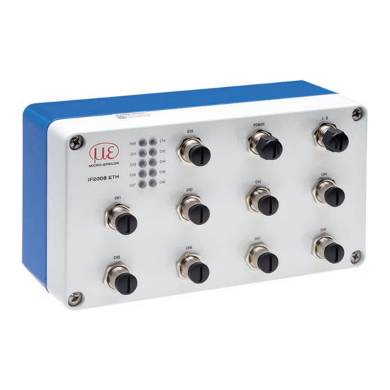
Hardware Hardware Connector Overview Fig. 2 Plug-in connections IF2008 ETH interface module Connector Description Flange socket, 4-pin, type Binder 09 3732 500 04 for Ethernet connection Flange connector, 5-pin, type Binder 09 3441 600 05 for power connection Flange connector, 12-pin, type Binder 09 3491 600 12 for I/O connection... -
Page 9: Pin Assignment
+ VDC (only for encoder) n.c. n.c. n.c. Fig. 7 Pin assignment sensor interface 1) Permissible supply voltage range 11 - 30 V 2) Bridge for HLL level on the IFC 24xx controller is set. IF2008 ETH Page 9... - Page 10 Hardware Connector Pin Signal IF2008ETH Signal Encoder +24 VDC n.c. Laser ON- n.c. Multi-function output n.c. ERROR input n.c. +5 VDC +5 VDC Fig. 8 Pin assignment encoder interface 1) Only for sensors IF2008 ETH Page 10...
-
Page 11: Led Overview
Hardware LED Overview Fig. 9 Status LEDs IF2008 ETH interface module LED color Description Power supply off Green Interface module is ready for operation Orange Interface module is in bootloader/flash mode Initialization of the interface module No Ethernet connection Orange... -
Page 12: Liability For Material Defects
Liability for Material Defects All components of the device have been checked and tested for functionality at the facto- ry. However, if defects occur despite our careful quality control, MICRO-EPSILON or your dealer must be notified immediately. The liability for material defects is 12 months from delivery. Within this period, defective parts, except for wearing parts, will be repaired or replaced free of charge, if the device is returned to MICRO-EPSILON with shipping costs prepaid. -
Page 13: Appendix A 1 Accessories
Connection cable to connect a confo- 29011145 cal IFC 24xx controller, 3 m long PCE2300-3/M12 Extension cable, 3 m Power supply and output cable 29011279 to connect an ILD2300 on the IF2008/ ETH, 3 m long IF2008 ETH Page 13... -
Page 14: A 2 Ascii Communication With Sensor
GETEXTINPUT Query digital inputs Chap. A 2.5.2.3 EXTINPUTMODE1 Programming digital input 1 Chap. A 2.5.2.4 EXTINPUTMODE2 Programming digital input 2 Chap. A 2.5.2.5 EXTINPUTMODE3 Programming digital input 3 Schaltausgänge Chap. A 2.5.3.1 EXTOUTSRC Programming digital outputs IF2008 ETH Page 14... -
Page 15: A 2.2 General Commands
If the IP address, net mask and/or gateway are not stated, their values remain un- changed. A 2.2.2.2 Setting Measurement Server MEASTRANSFER SERVER/TCP [<PORT>] Measured value output currently only on TCP server. - The port is freely selectable between 1024 and 65535. IF2008 ETH Page 15... -
Page 16: A 2.2.2.3 Size Of Tcp / Ip Packets
Defining the frequency of the internal timer The frequency can be freely adjusted from 0.1 Hz to 12 MHz (in Hz with three decimal places). The IF2008/ETH internally selects the next possible frequency which is support- IF2008 ETH Page 16... -
Page 17: A 2.2.3.2 Timer Pulse Width
Reset to factory settings - ALL: All setups are reset to factory settings. If ALL is not specified, only the current setup is reset. - NODEVICE: Only the settings for measurements are reset, the settings for interfaces are maintained. IF2008 ETH Page 17... -
Page 18: A 2.2.4.4 Restarting If2008/Eth
Carriage return can be quoted with \r and line feed with \n. Arbitrary binary sequences are entered with \xhh (hh is a hexadecimal code). Sensors with ASCII protocol (e.g. ILD2300) must contain the final \r\n within the quotation marks. IF2008 ETH Page 18... -
Page 19: A 2.3.2.3 Tunneling Sensor Commands (Ascii Version)
B the counter clock; in the REVERSE setting, the exact opposite is true. Encoder track C is always used to reset the counter. n = 1 ... 8 for the encoder channels 1 to 8. Counting direction of encoder. IF2008 ETH Page 19... -
Page 20: A 2.4.1.5 Encoder Detection Source
Defines the logic level of the digital inputs/outputs - LLL: Low level logic (Low 0.2 - 0.8 V High 4.5 - 5 V) - HLL: High level logic (Low 0.2 - 0.8 V High 23.5 - 24 V) IF2008 ETH Page 20... - Page 21 = 1 ... 4 for the digital outputs 1 to 4 Selects the source for the digital outputs - LOW, HIGH: Output has this fixed state - TIMER1 ... 3: Output is switched using the corresponding timer. IF2008 ETH Page 21...
- Page 22 10 = DigitalIn, 11 = reserved Data byte ( 8 bits): As received by the sensor Encoder transmission is always with 32 bits, i.e. four successive tuples. DigitalIn is transmitted with 4 bits (upper four bits are 0), i.e. one tuple. IF2008 ETH Page 22...
- Page 24 MICRO-EPSILON MESSTECHNIK GmbH & Co. KG X9751379-A012040HDR Koenigbacher Str. 15 · 94496 Ortenburg / Germany MICRO-EPSILON MESSTECHNIK Tel. +49 (0) 8542 / 168-0 · Fax +49 (0) 8542 / 168-90 *X9751379-A01* info@micro-epsilon.com · www.micro-epsilon.com...
Need help?
Do you have a question about the IF2008 ETH and is the answer not in the manual?
Questions and answers