Table of Contents
Advertisement
Quick Reference Guide
DF5-...
Frequency Inverters
02/02 AWB8230-1447GB
st
1
published 2002, edition 02/02
© Moeller GmbH, 53105 Bonn
Author:
Holger Friedrich
Editor:
Michael Kämper
Translator:
Dominik Kreuzer
All brand and product names are trademarks or registered
trademarks of the owner concerned.
All rights reserved, including those of the translation.
No part of this manual may be reproduced in any form
(printed, photocopy, microfilm or any otherprocess) or processed,
duplicated or distributed by means of electronic systems without
written permission of Moeller GmbH, Bonn.
Subject to alteration without notice.
Advertisement
Table of Contents

Related Manuals for Moeller DF5 Series


Summary of Contents for Moeller DF5 Series
- Page 1 No part of this manual may be reproduced in any form Author: Holger Friedrich (printed, photocopy, microfilm or any otherprocess) or processed, Editor: Michael Kämper duplicated or distributed by means of electronic systems without Translator: Dominik Kreuzer written permission of Moeller GmbH, Bonn. Subject to alteration without notice.
-
Page 2: Power Led
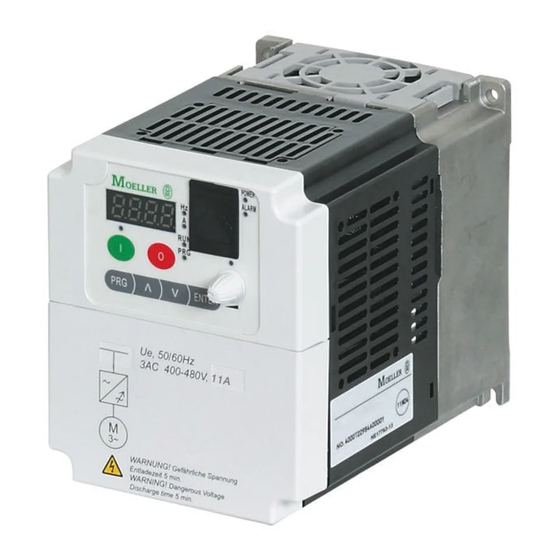
02/02 AWB8230-1447GB Quick Reference Guide DF5 Frequency Inverter Table 1: Explanation of the operating and indication elements Keypad Number Name Explanation The following illustration shows the LCD keypad of the DF5. RUN LED LED lights up in RUN mode if the frequency inverter is ready for operation or operational. - Page 3 02/02 AWB8230-1447GB Quick Reference Guide DF5 Frequency Inverter Using the keypad Example for changing over the control mode from control signal terminals (default) to the keypad. POWER ENTER POWER POWER POWER MIN/MAX DF5: 3 x POWER DF5: 3 x POWER MIN/MAX ENTER POWER...
-
Page 4: Restoring The Default Settings
02/02 AWB8230-1447GB Restoring the Default Settings Restoring the Default Settings Initialization Press the ENTER key to save the value. On the keypad, press both arrow keys and the PRG key at the Two different types of initialization are available: same time and keep them pressed. •... - Page 5 02/02 AWB8230-1447GB Quick Reference Guide DF5 Frequency Inverter Fault messages When an overcurrent, overvoltage or undervoltage occurs, the output of the DF5 frequency inverter is disabled to protect the DF5 from damage. The connected motor then coasts to a stop. The inverter remains in this condition until the fault message is acknowledged with the OFF key or the RST input.
-
Page 6: Other Messages
02/02 AWB8230-1447GB Other messages Other messages This section describes the messages issued by the DF5 frequency inverter, for example in standby mode when mains power is switched off. Display Cause The frequency inverter is in standby mode a reset signal is active. The mains voltage has been switched off. -
Page 7: Standard Form For User Defined Parameter Settings
02/02 AWB8230-1447GB Quick Reference Guide DF5 Frequency Inverter Standard form for user defined parameter settings The DF5 frequency inverters have programmable parameters. For a detailed description of the parameters, see the specified page in the manual (AWB8230-1412GB). In the free Setpoint columns below, you can list the changes you have made to the default settings. - Page 8 02/02 AWB8230-1447GB Standard form for user defined parameter settings Meaning Value range Def. Setpoint Percentage voltage increase with 0 to 99% manual boost Maximum boost at x % of the base 0 to 50 % 10.0 frequency U/f characteristic • 00: Constant torque curve •...
- Page 9 02/02 AWB8230-1447GB Quick Reference Guide DF5 Frequency Inverter Meaning Value range Def. Setpoint Restart mode • 00: Fault message • 01: 0 Hz start • 02: Synchronization to current motor speed and acceleration • 03: Synchronization and deceleration Permissible power failure duration 0.3 to 25 s Waiting time before restart 0.3 to 100 s...
- Page 10 02/02 AWB8230-1447GB Standard form for user defined parameter settings Meaning Value range Def. Setpoint Function of digital input 1 • 00: FWD, clockwise operation • 01: REV, anticlockwise operation • 02: FF1, first fixed frequency input • 03: FF2, second fixed frequency input •...
- Page 11 02/02 AWB8230-1447GB Quick Reference Guide DF5 Frequency Inverter Meaning Value range Setpoint Output frequency display – Output current display – Direction of rotation display – PID feedback display – Status of digital inputs 1 to 6 – Status of digital outputs 11 and 12 –...
Need help?
Do you have a question about the DF5 Series and is the answer not in the manual?
Questions and answers