Table of Contents
Advertisement
Quick Links
Hardware and Engineering
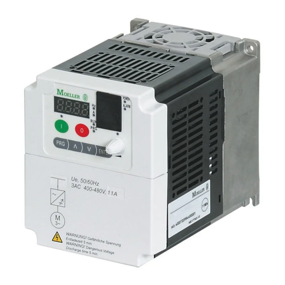
DF5-...
09/01 AWB8230-1412GB
1st published 2001, edition 09/01
© Moeller GmbH, Bonn
Author:
Holger Friedrich, Jörg Randermann
Editor:
Michael Kämper
Translator:
David Long
All brand and product names are trademarks or registered
trademarks of the owner concerned.
All rights reserved, including those of the translation.
No part of this manual may be reproduced in any form
(printed, photocopy, microfilm or any otherprocess) or processed,
duplicated or distributed by means of electronic systems without
written permission of Moeller GmbH, Bonn.
Subject to alterations without notice.
Advertisement
Table of Contents

Subscribe to Our Youtube Channel
Related Manuals for Moeller DF5 series


Summary of Contents for Moeller DF5 series
- Page 1 No part of this manual may be reproduced in any form Author: Holger Friedrich, Jörg Randermann (printed, photocopy, microfilm or any otherprocess) or processed, Editor: Michael Kämper duplicated or distributed by means of electronic systems without Translator: David Long written permission of Moeller GmbH, Bonn. Subject to alterations without notice.
- Page 2 Warning! Dangerous electrical voltage! Before commencing the installation • Disconnect the power supply of the device. • Devices that are designed for mounting in housings or control cabinets must only be operated and controlled after they have • Ensure that devices cannot be accidentally restarted. been installed with the housing closed.
- Page 3 • All shrouds and doors must be kept closed during operation. • In order to reduce hazards to persons or equipment, the user must include in the machine design measures that restrict the consequences of a malfunction or failure of the drive (increased motor speed or sudden standstill of motor).
-
Page 4: Table Of Contents
09/01 AWB8230-1412GB Contents About this Manual Abbreviations and symbols About DF5 series frequency inverters System overview Type code Inspecting the items supplied Layout of the DF5 – Frequency inverter characteristics Selection criteria Intended use Service and guarantee Engineering Features of the DF5 Connection to the mains –... - Page 5 09/01 AWB8230-1412GB Contents DF5 Operation Initial startup LCD keypad Operation with LCD keypad – Menu overview – Changing display and basic parameters – Changing the parameters of the extended parameter groups Display after the supply voltage is applied Operational warning message Programming the control signal terminals Overview Frequency display FM...
- Page 6 09/01 AWB8230-1412GB Contents Setting Parameters Setting the display parameters Basic functions – Input/display frequency value – Acceleration time 1 – Deceleration time 1 – Direction of rotation Setting the frequency and start command parameters – Definition of frequency setpoint value –...
- Page 7 09/01 AWB8230-1412GB Contents Appendix Technical Data Dimensions and weights Cables and fuses Mains contactors Radio interference filter Mains choke Connection examples – Operation through an external potentiometer – Operation through an analog setpoint value – Operation with fixed frequencies Abbreviations of parameters and functions Standard form for user defined parameter settings ®...
-
Page 8: Abbreviations And Symbols
09/01 AWB8230-1412GB About this Manual This manual describes the frequency inverters of the DF5 series. Read the manual carefully before you install and operate the frequency inverter. We assume that you have a good knowledge This manual contains special information which is required for... - Page 9 09/01 AWB8230-1412GB...
-
Page 10: System Overview
09/01 AWB8230-1412GB 1 About DF5 series frequency inverters System overview Figure 1: System overview a DF5 series frequency inverters-... e DE5-NET-DP interface module for PROFIBUS-DP b DE5-LZ... RFI filter f DEX-DEY-10 external keypad c DE5-CBL-...-ICL connection cable g DE5-KEY-RO3 external display module... -
Page 11: Type Code
09/01 AWB8230-1412GB About DF5 series frequency inverters Type code Type code and type designation of the DF5 series frequency inverter: DF5 - x x x - yyy Motor rating code Incoming supply: EU rated voltage (230 V/400 V) Version and model number... -
Page 12: Inspecting The Items Supplied
09/01 AWB8230-1412GB Inspecting the items supplied Inspecting the items supplied Frequency inverters of the DF5 series frequency inverters are care- Open the packaging with suitable tools and inspect the contents fully packed before delivery. The device may be transported only in... -
Page 13: Layout Of The Df5
09/01 AWB8230-1412GB About DF5 series frequency inverters Layout of the DF5 Figure 4: Designations of the DF5 a Front cover, can be opened without tools h Power terminals b Integrated keypad i Screw for opening the front enclosure c Terminal shroud... -
Page 14: Frequency Inverter Characteristics
Selection criteria Frequency inverter characteristics Selection criteria The DF5 series convert the voltage and frequency of an existing The frequency inverter is selected to suit the rated motor current. three-phase supply to a DC voltage and use this voltage to gene- The output rated current of the frequency inverter must however, rate a three-phase supply with adjustable voltage and frequency. -
Page 15: Intended Use
93/68/EEC and Directive 89/336/EEC, as amended by 93/68/ EEC). Frequency inverters of the DF5 series are suitable for use in public and non-public networks in the described system configuration. Depending on their location of use, external filtering may be necessary. -
Page 16: Features Of The Df5
09/01 AWB8230-1412GB 2 Engineering This chapter describes the ”Features of the DF5” as well as guide- • Connection to the mains lines and regulations concerning the following subjects: • EMC guidelines Features of the DF5 Ambient temperatures Operation Ta = –10 to +40 °C with rated current I without derating, up to +50 °C with reduced carrier frequency of 2 kHz and reduced output current to 80 % I Storage... -
Page 17: Connection To The Mains
This constitutes an individual TN-system for the frequency inverter. • Operation of the frequency inverters of the DF5 series with TT systems is possible without limitation. Adhere to the rated data of the DF5 series frequency inverters. Mains voltage, Mains frequency... -
Page 18: Interaction With Compensation Devices
Interaction with compensation devices Protection of persons and domestic animals with residual- current protective devices The DF5 series frequency inverters only accept a minimal funda- mental reactive power from the AC voltage supply. Compensation Residual-current circuit-breakers RCCB (according to VDE 0100, is therefore unnecessary. -
Page 19: Mains Contactor
L1, L2, L3 (type dependant). It allows the operational switch on reactor) is connected to the mains side input cables L1, L2, L3 (type and off of the DF5 series frequency inverters from the mains supply dependent). It reduces the harmonics and leads to a reduction of as well as shutdown during a fault. -
Page 20: Emc Guidelines
(first environment) with the assigned radio interference filters. When operating the frequency inverters of the DF5 series in coun- tries which are part of the European Union (EU), the EMC guideline A domestic environment can be understood to be a connection 89/336/EEC must be observed. - Page 21 09/01 AWB8230-1412GB...
-
Page 22: Df5 Installation
09/01 AWB8230-1412GB 3 Installation The DF5 series frequency inverters should be installed in a control panel or in a metal enclosure (e.g. IP54). During installation or assembly operations on the frequency inverter, all ventilation slots and openings should be covered to ensure that foreign bodies and objects do not penetrate the device. -
Page 23: Installation Dimensions
09/01 AWB8230-1412GB Installation Installation dimensions Please ensure that the front cover of the enclosure can always be opened and closed without impediment to ensure that the control A free space of 100 mm minimum is required above and below the terminals can be connected. -
Page 24: Df5 Attachment
09/01 AWB8230-1412GB DF5 Installation DF5 attachment Install the DF5 series frequency inverter according to Fig. 8 and tighten the screws with the following torques (a Table 1): Figure 8: DF5 attachment Table 1: Tightening torque's of the attachment screws [mm]... -
Page 25: Emc Compliance
Page 115) enable the installation below (foot-print) or on the side from the frequency inverters. (book-type) of the DF5 series frequency inverters. We recommend the following measures for EMC compliant instal- lation: •... -
Page 26: Emc Measures In The Control Panel
• the protective conductor must have a cross-section f 10 mm • the protective conductor is monitored to ensure continuity or • an additional protective conductor is also installed. L/L1 For the frequency inverters of the DF5 series use the assigned filter N/L3 DE5-LZ..EMC measures in the control panel... -
Page 27: Grounding
09/01 AWB8230-1412GB Installation Fit additional RFI filters or mains filters and frequency inverters as Grounding closely as possible to each other and on a single metal plate Connect the ground plate (mounting plate) with the protective (mounting plate). earth using a short cable. To achieve the best results, all conduc- Lay cables in the control cabinet as near as possible to the ground ting components (frequency inverter, mains filter, motor filter, potential. - Page 28 09/01 AWB8230-1412GB EMC compliance In an EMC-compliant control cabinet (metal-enclosed, damped to The screened cable between frequency inverter and motor should about 10 dB), the motor cables do not need to be screened be as short as possible. Connect the screen to earth at both ends provided that the frequency inverter and motor cables are spatially of the cable using a large contact surface connection.
-
Page 29: Electrical Connection
09/01 AWB8230-1412GB Installation Electrical connection In this section, you will find information for connection of the motor and the supply voltage to the power terminals, and the signal cables to the control terminals and signalling relay. Warning! The wiring stages may only commence after the frequency inverters have been correctly installed and attached. - Page 30 09/01 AWB8230-1412GB Electrical connection 3 h 400 V, 50/60 Hz I > I > I > K14 K12 K11 DE4-BM4... –UG DC+ DC– ˜ Figure 18: Power connection, example with 400 V a Network configuration, mains voltage, mains frequency g Motor filter interaction with p.f.
-
Page 31: Connecting The Power Section
09/01 AWB8230-1412GB Installation Connecting the power section Loosen the screw The flap on the front enclosure must be opened in order to connect the cables to the supply voltage and signal relay terminals. Complete the following steps with the tools stated and ENTER without the use of force. - Page 32 09/01 AWB8230-1412GB Electrical connection Flap open the front cover and remove the terminal shroud Power terminal arrangement The arrangement of the power terminals can be seen in the following figure. DC– L/L1 N/L3 Figure 22: Arrangement of the power terminals a Internal connection.
- Page 33 09/01 AWB8230-1412GB Installation Power terminal connection Laying the cables Lay the cables for the power section separately from the signal Warning! cables and control cables. The supply voltage must suit the frequency inverter which is selected (a Section ”Appendix”, Page 107): The motor cables which are to be connected must be screened.
- Page 34 09/01 AWB8230-1412GB Electrical connection Figure 23: Cable connection to the power terminals Connecting the supply voltage Connect the supply voltage to the power terminals: – Single-phase supply voltage: L, N and PE – Three-phase supply voltage: L1, L2, L3 and PE...
- Page 35 09/01 AWB8230-1412GB Installation Connecting the motor cable Connect the motor cable to the U, V, W and PE terminals: F1, Q1 = L1 L2 L3 DF5-322... DF5-322... 1 h 230 V, 50/60 Hz 3 h 230 V, 50/60 Hz DF5-340... 3 h 400 V, 50/60 Hz DC+ DC–...
- Page 36 (less than approx. 25 Hz) can lead to thermal damage (overheating) with self-ventilated motors. Possible In the factory default setting, frequency inverters of the DF5 series counter-measures include: Over-dimensioning or external have a clockwise rotating field. Rotation of the motor shaft to the cooling independant of motor speed.
- Page 37 Installation Parallel connection of motors on a frequency inverter The DF5 series frequency inverters can control multiple motors connected in parallel. If differing motor speeds are required, they must be selected via the number of pole pairs and/or the gear transmission ratio.
- Page 38 09/01 AWB8230-1412GB Electrical connection Motor filters, dv/dt filters, sinusoidal filters Bypass operation Motor filters (chokes) compensate for capacitive currents with If you want to have the option of operating the motor with the long motor cables and with grouped drives (multiple connection of frequency inverter or directly from the mains supply, the incoming parallel drives to a single inverter).
-
Page 39: Connecting The Signalling Relay
09/01 AWB8230-1412GB Installation Connecting the signalling relay The following figure indicates the position of the signalling relay. Figure 30: Connecting the signalling relay a Signalling relay terminals When connecting the signalling relay, support the open enclosure front. Table 4: Description of the signalling relay terminals Terminal desig- Description nation... - Page 40 09/01 AWB8230-1412GB Electrical connection Fit the terminal shroud to the enclosure again and close the enclosure front. Figure 31: Close the power section...
-
Page 41: Connecting The Control Signal Terminals
09/01 AWB8230-1412GB Installation Connecting the control signal terminals ESD measures Discharge yourself on an earthed surface before touching The following figure shows the arrangement of the individual control signal terminals. the frequency inverter and its accessories. This prevents damage to the devices through electrostatic discharge. - Page 42 09/01 AWB8230-1412GB Electrical connection Function Level Default setting Technical data, description External control voltage Up to 27 V – Connection: Reference potential (0 V) of the input external voltage source for the transistor outputs, terminals 11 and 12. Load carrying capacity: Up to 100 mA (sum of terminals 11 + 12) Transistor output Up to 27 V = CM2...
- Page 43 09/01 AWB8230-1412GB Installation When connecting a relay to one of the digital outputs 11 or 12, connect a free-wheel diode in parallel with the relay, so that the self-induction voltage generated when the relay is switched off cannot destroy the digital outputs. + 24 V 100 mA f 100...
- Page 44 09/01 AWB8230-1412GB Electrical connection Example for the protective circuit of the digital inputs when the internal P24 supply voltage is used, or when a separate external 24 V power supply is used: +24 V 24 V +24 V +24 V +24 V 24 V Figure 36: Triggering of the digital inputs...
- Page 45 09/01 AWB8230-1412GB Installation Caution! Before commissioning, remove the covering on the upper ventilation slots and openings, as the frequency inverter will otherwise overheat a Fig. 37. Figure 37: Removing the upper cover...
-
Page 46: Df5 Operation
09/01 AWB8230-1412GB 4 DF5 Operation This section describes how to commission the DF5 series frequency The control signal terminals are wired as follows. inverters and deals with issues that need to be observed during its operation. Initial startup Observe the following points before you take the frequency inverter into operation: •... -
Page 47: Lcd Keypad
09/01 AWB8230-1412GB DF5 Operation Table 7: Explanation of the operating and indication elements Caution! Number Name Explanation Check the following points during or after the “initial operation” so that damage to the motor does not occur: RUN LED LED lights up in RUN mode, if the •... -
Page 48: Changing Display And Basic Parameters
09/01 AWB8230-1412GB Operation with LCD keypad Table 8: Explanation of the parameters Display Explanation Display parameter Output frequency display d 01 Output current display d 02 d 03 Direction of rotation display PID feedback display d 04 Digital inputs 1 to 5 status d 05 Status of digital outputs 11 and 12 d 06... -
Page 49: Changing The Parameters Of The Extended Parameter Groups
09/01 AWB8230-1412GB DF5 Operation Example for changing acceleration time 1: PNU F02 Changing the parameters of the extended parameter The frequency inverter is in the display mode and the RUN lamp is groups lit. The following example illustrates how to change PNU A03 of the Press the PRG key. -
Page 50: Display After The Supply Voltage Is Applied
09/01 AWB8230-1412GB Display after the supply voltage is applied The frequency inverter changes over to the display mode and displays the current frequency. A03 = 49.9 ENTER > A03 = 50.0 Figure 42: Change the base frequency (example with default setting) a Display dependent on the selected display parameter PNU d01 to d09 b Display of the most recently changed parameter Display after the supply voltage is applied... -
Page 51: Operational Warning Message
09/01 AWB8230-1412GB DF5 Operation Operational warning message Warning! Warning! If the supply voltage recovers after a brief failure, the When the supply voltage for the frequency inverter is motor may restart automatically if a start signal is still applied when the start signal is active, the motor will present. -
Page 52: Programming The Control Signal Terminals
09/01 AWB8230-1412GB 5 Programming the control signal terminals This section describes how to assign various functions to the control signal terminals. Overview Table 9 provides an overview of the control signal terminals and a brief description of the functions which you can assign to the programmable digital inputs and outputs. - Page 53 09/01 AWB8230-1412GB Programming the control signal terminals Name Value Function Description External fault When the EXT input is switched on, the fault signal activates PNU E12 and the motor switches off. The fault signal can be acknowledged, for example, with the RST input. Restart inhibit When the USP input is switched on, the restart inhibit is active.
- Page 54 09/01 AWB8230-1412GB Overview Name Value Function Description Digital outputs 11 and 12 Parameter definition under PNU C21 and C22 Signal when frequency is Connection of a signal reached or exceeded relay to digital output 11 or 12: 24 V 50 mA Transistor output (open collector) = setpoint frequency...
-
Page 55: Frequency Display Fm
09/01 AWB8230-1412GB Programming the control signal terminals Frequency display FM The FM terminal provides the output frequency or the motor The selection between the frequency display and display of the current as a frequency signal. motor current is made under PNU C23. Name Adjustable in Value... -
Page 56: Digital Frequency Display
09/01 AWB8230-1412GB Frequency display FM Digital frequency display The frequency of this signal (PNU C23 = 02) changes proportio- nally to the output frequency. The pulse duty factor remains constant at about 50 %. – Digital frequency meter T = 1/(output frequency x factor) Figure 45: Digital frequency meter connection The signal frequency results from the product of the current output frequency and an adjustable factor at PNU b86. -
Page 57: Programmable Digital Inputs 1 To 5
09/01 AWB8230-1412GB Programming the control signal terminals Programmable digital inputs 1 to 5 You can assign various functions to terminals 1 to 5. Depending Tabelle 11: Functions of the digital inputs on your requirements, these terminals can be configured as Value Function Description... -
Page 58: Start/Stop
09/01 AWB8230-1412GB Start/Stop Start/Stop Clockwise rotation FWD Issue start command If you activate a digital input which has been configured as a FWD By default, the start command is issued through the inputs confi- input, the motor starts to run in a clockwise direction. If you deac- gured as FWD or REV. -
Page 59: Fixed Frequency Ff1 To Ff4 Selection
09/01 AWB8230-1412GB Programming the control signal terminals Fixed frequency FF1 to FF4 selection With the digital inputs configured as FF1 to FF4 you can select up to 16 user-definable fixed frequencies (including frequency setpoints), depending on which of the inputs is active or inactive (a Table 13). - Page 60 09/01 AWB8230-1412GB Fixed frequency FF1 to FF4 selection Specifying frequency setpoints • via analog input O (0 to 10 V) or OI (4 to 20 mA), The frequency setpoint value can be assigned in one of three ways, PNU A01 = 01 (WE); dependent on PNU A01: •...
-
Page 61: Current Setpoint Value At (4 To 20 Ma)
09/01 AWB8230-1412GB Programming the control signal terminals Current setpoint value AT (4 to 20 mA) When the digital input which has been configured as AT is active, the setpoint value is defined by the current flow (4 to 20 mA) on terminal OI. -
Page 62: Second Time Ramp 2Ch
09/01 AWB8230-1412GB Fixed frequency FF1 to FF4 selection Second time ramp 2CH If the digital input which has been configured as 2CH is active, the FWD/REV motor will be accelerated or braked with the second acceleration or deceleration time. If the 2CH input is again deactivated, a chan- geover to the first acceleration/deceleration time takes place. -
Page 63: Controller Inhibit And Coasting Of The Motor Frs (Free Run Stop)
09/01 AWB8230-1412GB Programming the control signal terminals Controller inhibit and coasting of the motor FRS (free run stop) FWD/REV If you activate the digital input configured as FRS, the motor is switched off and coasts to a stop (for example if an Emergency- Stop is made). -
Page 64: External Fault Message Ext
09/01 AWB8230-1412GB Fixed frequency FF1 to FF4 selection External fault message EXT If the digital input configured as EXT is activated, the fault message E12 is initiated (e.g. an input used for the bimetal contacts). The fault message remains active even if the EXT input is deactivated again and must be acknowledged with a reset. -
Page 65: Restart Inhibit Usp
09/01 AWB8230-1412GB Programming the control signal terminals Restart inhibit USP Program one of the digital inputs 1 to 5 as USP, by inputting the value 13 under the respective PNU (C01 to C05). If the digital input configured as USP is activated, the restart inhibit is also activated. -
Page 66: Reset: Rst
09/01 AWB8230-1412GB Fixed frequency FF1 to FF4 selection Reset: RST Warning! A fault message can be acknowledged by activating and subse- If a malfunction is responded to by a reset, the motor will quently deactivating (i.e. resetting) the digital input configured as start immediately if a start signal is applied simultane- RST. -
Page 67: Jog Mode (Jog)
09/01 AWB8230-1412GB Programming the control signal terminals Jog mode (JOG) Input under PNU A38 the frequency which is to be applied to the motor when jog mode is active. When the digital input configured as JOG is activated, the motor can be operated in jog mode. -
Page 68: Ptc Thermistor Input: Ptc
09/01 AWB8230-1412GB Fixed frequency FF1 to FF4 selection PTC thermistor input: PTC If programmable digital input 5 is configured as PTC, the motor temperature can be monitored with a thermistor with a positive temperature coefficient (PTC) connected to terminals 5 and L. If the resistance of the thermistor rises above 3000 O (g10 %), the motor is stopped and fault message E35 is displayed. -
Page 69: Software Protection Sft
09/01 AWB8230-1412GB Programming the control signal terminals Software protection SFT If you activate the digital input configured as SFT, the configured parameters cannot be overwritten unintentionally. Figure 64: Digital input 3 configured as “Software protection” SFT First of all set under PNU b31 if the software protection should also apply for the frequency setting under PNU F01. -
Page 70: Programmable Digital Outputs 11 And
09/01 AWB8230-1412GB Programmable digital outputs 11 and 12 Programmable digital outputs 11 and 12 The programmable digital outputs 11 and 12 are open collector Programmable digital inputs 11 and 12 are by default configured transistor outputs (a Fig. 65), to which e.g. relays can be as break (NC) contacts. -
Page 71: Frequency Value Messages Fa1/Fa2
09/01 AWB8230-1412GB Programming the control signal terminals Frequency value messages FA1/FA2 The digital output configured as FA1 will be activated as soon as the setpoint frequency is achieved. The digital output configured as FA2 is activated as long as the frequencies set under PNU C42 and C43 are exceeded. - Page 72 09/01 AWB8230-1412GB Frequency value messages FA1/FA2 Name Adjustable in Value Function RUN mode Frequency from – 0 to 360 Hz The digital output (11 or 12) PNU C42 which FA2 configured as FA2 becomes becomes active active when the frequency PNU C43 during accelera- entered here is exceeded...
-
Page 73: Run Operational
09/01 AWB8230-1412GB Programming the control signal terminals RUN operational The digital output configured as RUN remains activated as long as FWD/REV a frequency not equal to 0 Hz is present, i.e. as long as the motor is driven in a clockwise or anticlockwise direction. 24 V 50 mA Figure 70:... -
Page 74: Overload Message Ol
09/01 AWB8230-1412GB Frequency value messages FA1/FA2 Overload message OL PNU C41 The digital output configured as OL is activated when a freely selectable motor current is exceeded. The OL output is active as long as the motor current is higher than this threshold. 24 V 50 mA Figure 72:... -
Page 75: Pid Controller Deviation Message Od
09/01 AWB8230-1412GB Programming the control signal terminals PID controller deviation message OD The digital output configured as OD is activated when a user defi- nable PID deviation (actual value versus setpoint value) is PNU C44 exceeded. The OD output remains active as long as this differential is exceeded. -
Page 76: Error Message Al
09/01 AWB8230-1412GB Frequency value messages FA1/FA2 Error message AL The digital output configured as AL activates when a fault has occurred. 24 V 50 mA Figure 75: Digital output 11 configured as AL (fault occurrence) Program one of the digital inputs 11 or 12 as the AL output, by setting the value 05 under PNU C21 or C22. -
Page 77: Signalling Relay Terminals K11, K12, K14
09/01 AWB8230-1412GB Programming the control signal terminals Signalling relay terminals K11, K12, K14 If a fault occurs, the signalling relay (changeover) is triggered. The switching conditions can be programmed as required. Table 18: Default setting of the signalling relay Default setting of the signalling relay Reconfigured signalling relay terminals (PNU C33 = 00) Fault or DF5 switched off Operating message... -
Page 78: Setting Parameters
09/01 AWB8230-1412GB 6 Setting Parameters The parameters listed in this section can be set using the keypad. The adjustment and setting possibilities listed below are themati- cally arranged according to their function. This provides a clear overview of all parameters assigned to a particular functional area (e.g. -
Page 79: Basic Functions
09/01 AWB8230-1412GB Setting Parameters Basic functions Input/display frequency value • via analog input O (0 to 10 V) or OI (4 to 20 mA), PNU A01 = 01 (default setting); PNU F01 displays the current frequency setpoint value or the •... -
Page 80: Deceleration Time
09/01 AWB8230-1412GB Basic functions Deceleration time 1 Deceleration time 1 defines the time in which the motor brakes to 0 Hz after a stop command. Name Adjustable in Value Function RUN mode Deceleration 0.1 to 3000 s Resolution of 0.1 s at an input of 0.1 to 999.9 10.0 time 1 Resolution of 1 s at an input of 1000 to 3000... -
Page 81: Setting The Frequency And Start Command Parameters
09/01 AWB8230-1412GB Setting Parameters Setting the frequency and start command parameters This section describes the methods for adjusting and setting the start command and basic frequency-related parameters. Definition of frequency setpoint value With PNU A01, you set how the frequency setpoint value is to be defined: •... -
Page 82: Base Frequency
09/01 AWB8230-1412GB Setting the frequency and start command parameters Base frequency The base frequency is the frequency at which the output voltage has its maximum value. Name Adjustable in Value RUN mode Base frequency – 50 to 360 Hz Maximum end frequency If you want to set another frequency range with a constant voltage that lies beyond the base frequency set under PNU A03, this frequency is set with PNU A04. -
Page 83: Analog Setpoint Value Matching
09/01 AWB8230-1412GB Setting Parameters Analog setpoint value matching The external setpoint signal can be specifically matched with para- meters PNU A11 to A16, which are described below. A configu- [Hz] rable voltage or current setpoint range can be assigned to a confi- PNU A12 gurable frequency range. -
Page 84: Voltage/Frequency Characteristics And Boost
09/01 AWB8230-1412GB Voltage/frequency characteristics and boost Voltage/frequency characteristics and boost The boost with the V/f characteristic has the effect of boosting the voltage (and consequently boosting the torque) in the lower frequency range. The manual boost raises the voltage in the frequency range from the start frequency (standard setting 0.5 Hz) to half the base frequency (25 Hz with the standard setting of 50 Hz) in every operating stage (acceleration, normal operation,... -
Page 85: Dc Braking (Dc-Break)
09/01 AWB8230-1412GB Setting Parameters DC braking (DC-Break) To activate DC braking, apply a stop signal (PNU A51 to A55). By Caution! applying a pulsed DC voltage to the motor stator, a braking torque DC braking results in additional heating of the motor. You is induced in the rotor and acts against the rotation of the motor. -
Page 86: Operating Frequency Range
09/01 AWB8230-1412GB Operating frequency range Operating frequency range The frequency range which is determined by the values configured To avoid resonance within the drive system, it is possible to under PNU b82 (start frequency) and PNU A04 (end frequency) program three frequency jumps under PNU A63 to A68. In the can be limited by PNU A61 and A62 (a Fig. -
Page 87: Pid Controller
09/01 AWB8230-1412GB Setting Parameters PID controller The DF5 series frequency inverter is a PID controller. This can be • With the aid of a scale adjustment, you can match the setpoint used, for example, for flow and throughput controllers with fans signal and/or the actual value signal to the actual physical and pumps. - Page 88 The reciprocal value of the integration gain is the integration time =1/K With the DF5 series frequency inverters, set the integration time ). The value may be between 0.5 s and 150 s. To disable the integral component, enter 0.0.
- Page 89 09/01 AWB8230-1412GB Setting Parameters Setting the PID parameters Values for the PID parameters must be chosen depending on the application. and the system’s control characteristics. To ensure correct PID closed loop control, the following points should be observed: • Stable steady-state behaviour, •...
-
Page 90: Structure And Parameters Of The Pid Controller
09/01 AWB8230-1412GB PID controller Structure and parameters of the PID controller You can switch between both modes with PNU A71 (PID control active/inactive). PID controller active/inactive DF5 frequency inverters can operate in one of the following two control modes: • Frequency control active (i.e. PID closed loop control inactive) •... - Page 91 09/01 AWB8230-1412GB Setting Parameters Function Adjustable in Value Function RUN mode Defined – Definition with the potentiometer on the keypad frequency Definition via analog input O (0 to 10 V) or OI (4 to 20 mA) setpoint Definition under PNU F01 and/or PNU A20 Frequency with –...
- Page 92 09/01 AWB8230-1412GB PID controller Setpoint definition Actual value feedback and actual value signal matching There are three ways of entering the setpoints: You can specify the actual value signal as follows: • Keypad • With an analog voltage on control signal terminal O •...
- Page 93 Summary of the relevant parameters frequency control mode, however, as this mode is used in most With the DF5 series frequency inverters, the same parameters are cases. When the PID mode is used, some of the parameters have used for both the frequency control mode and the PID mode. The other designations.
- Page 94 Assignment of the digital inputs through the same analog input terminal. The DF5 series have five programmable digital inputs. Assign the functions FF1 to FF4 to four of the inputs. Use PNU C01 to C05 for Please note that the frequency inverter brakes and stops according...
-
Page 95: Example For Setting K P And T I
09/01 AWB8230-1412GB Setting Parameters Example for setting K and T Setpoint number (PNU) As for the parameter changes, check the output frequency or the Setpoint value 0 feedback actual value signal with an oscilloscope (a Fig. 84 to (PNU A20 or F 01) Fig. -
Page 96: Application Examples
09/01 AWB8230-1412GB PID controller Application examples Flow control The example shown in the figure below has the setpoint values This section contains some setting examples for practical 150 m /min and 300 m /min: applications. 500 m /min 300 m /min 150 m /min... - Page 97 09/01 AWB8230-1412GB Setting Parameters Temperature control be implemented: if the temperature is above the setpoint, the With the flow control in the previous example, the frequency inverter must increase its output frequency to increase the speed inverter’s output frequency increases if the feedback signal is less of the connected fan.
-
Page 98: Automatic Voltage Regulation (Avr)
09/01 AWB8230-1412GB Automatic voltage regulation (AVR) Automatic voltage regulation (AVR) The AVR function stabilizes the motor voltage if there are fluctua- Regenerative motor operation (without AVR function) results in a tions on the DC bus voltage. These deviations result from, for rise in the DC bus voltage in the deceleration phase (particularly example: with very short deceleration times), which also leads to a corres-... -
Page 99: Time Ramps
09/01 AWB8230-1412GB Setting Parameters Time ramps During operation, you can switch over from the time ramps confi- gured under PNU F02 and F03 to those configured under PNU A92 and A93. This can be done either by applying an external signal to input 2CH at any time or when the frequencies configured under PNU A95 and A96 are reached. -
Page 100: Automatic Restart After A Fault
09/01 AWB8230-1412GB Automatic restart after a fault With the default settings, each malfunction triggers a fault Automatic restart after a fault message. An automatic restart is possible after the following fault messages have occurred: Warning! When a fault has occurred, this function initiates an auto- •... -
Page 101: Electronic Motor Protection
09/01 AWB8230-1412GB Setting Parameters Electronic motor protection The DF5 series frequency inverters can monitor the temperature of rated motor current, the motor cannot be monitored with this connected motors with an electronic bimetallic relay. With function. In this case, PTC thermistors or bimetal contacts in the PNU b12, you can match the electronic motor protection to the motor windings must be used. -
Page 102: Current Limit
09/01 AWB8230-1412GB Current limit Current limit With the current limit parameter, the motor current can be limited. To reduce the load current, the frequency rise ends in the accele- ration phase or the output frequency is reduced in the static phase, as soon as the output current exceeds the set current limit. -
Page 103: Parameter Protection
09/01 AWB8230-1412GB Setting Parameters Parameter protection The four following methods of parameter protection are available: Name Adjustable in Value Function RUN mode Software – Parameter protection through SFT input; all functions inhibited parameter Parameter protection through SFT input; input via PNU F01 possible protection Parameter protection without SFT input;... -
Page 104: Other Functions
09/01 AWB8230-1412GB Other functions Other functions Carrier frequency Initialization High carrier frequencies result in less motor noise and lower power Two different types of initialization are available: losses in the motor but a higher dissipation in the power amplifiers • Clearing the fault history register and more noise in the mains and motor cables. -
Page 105: Inhibit Of The Off Key
09/01 AWB8230-1412GB Setting Parameters Inhibit of the OFF key The OFF key located on the keypad or remote operating unit can be inhibited here. Name Adjustable in Value Function RUN mode OFF key – OFF key always active disabled OFF key not active with control via the FWD/REV terminals Motor restart after cancellation of the FRS signal Activation of the digital input configured as FRS causes the inverter to shut down, leaving the motor to coast. -
Page 106: Messages
09/01 AWB8230-1412GB 7 Messages In this section, the messages issued by the DF5 series frequency inverters are listed and explained. Fault messages At overcurrent, overvoltage and undervoltage conditions, the output of the DF5 series frequency inverters is shut down to protect against damage. -
Page 107: Other Messages
09/01 AWB8230-1412GB Messages Other messages This section describes the messages issued by the DF5 series frequency inverters in standby mode, when the mains voltage is switched off, etc. Display Cause The frequency inverter is in standby mode a reset signal is active. -
Page 108: Fault Correction
09/01 AWB8230-1412GB 8 Fault correction Fault Condition Possible cause Remedy The motor will not There is no voltage Is voltage applied to terminals L, N and/or L1, L2 Check terminals L1, L2, L3 and U, V, W. start. present at outputs U, and L3? If yes, is the ON lamp lit? Switch on the supply voltage. - Page 109 09/01 AWB8230-1412GB Fault correction Fault Condition Possible cause Remedy The motor does not – Are the load changes on the motor too high? Select a frequency inverter and motor with a operate smoothly. higher performance. Reduce the level of load changes. Do resonant frequencies occur on the motor? Mask these frequencies with the frequency jumps (PNU A63 to A68, a Section ”Operating...
-
Page 110: Technical Data
09/01 AWB8230-1412GB Appendix Technical Data The following table contains the technical data for the 230 V series. DF5-322-... Protection class according to EN 60529 IP20 Overvoltage category Maximum permissible effective motor power in kW, details 0.18 0.37 0.55 0.75 for four pole three-phase current asynchronous motors Maximum permissible apparent motor 230 V power in kVA... - Page 111 09/01 AWB8230-1412GB Appendix DF5-322-... Digital control inputs programmable as • FWD: Start/stop clockwise rotation • REV: Start/stop anticlockwise rotation • FF1 to FF4: Fixed frequency selection • JOG: Jog mode • AT: Use setpoint value 4 to 20 mA • 2CH: Second time ramp •...
- Page 112 09/01 AWB8230-1412GB Technical Data The following data contains the technical data for the 400 V series. DF5-340-... Protection class according to EN 60529 IP20 Overvoltage category Maximum permissible effective motor power in kW, details 0.37 0.75 for four pole three-phase current asynchronous motors Maximum permissible apparent motor power in kVA for 10.3 12.7...
- Page 113 09/01 AWB8230-1412GB Appendix DF5-340-... Digital control inputs programmable as • FWD: Start/stop clockwise rotation • REV: Start/stop anticlockwise rotation • FF1 to FF4: Fixed frequency selection • JOG: Jog mode • AT: Use setpoint value 4 to 20 mA • 2CH: Second time ramp •...
-
Page 114: Dimensions And Weights
09/01 AWB8230-1412GB Dimensions and weights Dimensions and weights Figure 95: Sizes for DF5 Figure 96: Dimensions for DF5 DF5- [kg] 322-018 88.5 0.85 322-037 322-055 322-075 340-037 340-075 – 340-1K5 322-1K1 184.5 322-1K5 322-2K2 184.5 – 340-2K2 340-3K0 340-4K0 340-5K5 340-7K5... -
Page 115: Cables And Fuses
The cross-sections of the cables and line protection fuses used must correspond with the applicable standards. Connection to the power supply L1, L2, L3, N, U, V, W, PE (2x) Moeller 322-018 1/3-phase 230 V M10 A 10 A FAZ-1N-B10, PKZM0-10... -
Page 116: Mains Contactors
09/01 AWB8230-1412GB Mains contactors Mains contactors The mains contactors listed here assume the network’s P1DILEM rated current (I ) without mains choke/mains filter. Their P1DIL00M selection is based on the thermal current (AC-1). Caution! DILEEM Jog mode must not be used through the mains contactor DILEM DIL00M (pause time f 180 s between switching off and on) - Page 117 09/01 AWB8230-1412GB Appendix DF5- DF5- phase current Mains contactor + Paralleling link Open/enclosed Model AC-1 [A] 3 ~ 400 V connection 340-037 20/16 DILEEM – 340-075 340-1K5 340-2K2 340-3K0 DIL00M 340-4K0 DIL00M 340-5K5 16.5 35/30 DIL0M 340-7K5 35/30 DIL0M 1) For a single-phase supply connection, supplement the mains contactors with the corresponding parallel connectors (terminals 1-3-5 and 2-4-6). The fourth pin can be broken off.
-
Page 118: Radio Interference Filter
09/01 AWB8230-1412GB Radio interference filter Radio interference filter RFI filters have discharge currents to earth, which can be higher than the nominal values in the event of a fault (phase failure, load unbalance). To avoid dangerous voltages, the filters must be earthed before use. -
Page 119: Mains Choke
09/01 AWB8230-1412GB Appendix Mains choke Figure 99: DE4-LN... mains choke When the frequency inverter is operating at its rated current limit, the main choke causes a reduction of the frequency inverter's greatest possible output voltage (U to about 96 % of the mains voltage (U DF5- Mains Mains current... -
Page 120: Connection Examples
09/01 AWB8230-1412GB Connection examples Connection examples Operation through an external potentiometer Operation through an analog setpoint value 4 – 20 mA (1 – 10 kO) – 0 – 10 V 1 mA Figure 101: Analog setpoint value definition Figure 100: Connect an external potentiometer Configuration of the parameters Configuration of the parameters Value... -
Page 121: Operation With Fixed Frequencies
09/01 AWB8230-1412GB Appendix Operation with fixed frequencies Method of operation Inputs 1 and 2 function exactly as described in the first example. With the activation of one or both fixed frequency inputs FF1 and FF2, the current frequency setpoint applied to the motor is replaced by the fixed frequency determined by FF1 and FF2, and the motor brakes or accelerates according to the fixed frequency applied. -
Page 122: Abbreviations Of Parameters And Functions
09/01 AWB8230-1412GB Abbreviations of parameters and functions Abbreviations of parameters and functions Designation Function, description Message 2-stage Acceleration und Deceleration Alarm signal Analog input voltage/current select Automatic Voltage Regulation External Trip FA... Frequency arrival FF... Fixed Frequency Free-run Stop Forward Run Jogging Output deviaton for PID control Overload advance signal... -
Page 123: Standard Form For User Defined Parameter Settings
09/01 AWB8230-1412GB Appendix Standard form for user defined parameter settings The DF5 series frequency inverters have programmable parame- ters. In the free Setpoint columns below, you can list the changes you have made from the default settings. Function Setpoint Frequency setpoint value Acceleration time 1 in s 10.0... - Page 124 09/01 AWB8230-1412GB Standard form for user defined parameter settings Function Setpoint 14th fixed frequency 15th fixed frequency Frequency in jog mode Motor stop in jog mode via • 00: Free run • 01: Deceleration ramp • 02: DC braking Boost characteristics •...
- Page 125 09/01 AWB8230-1412GB Appendix Function Setpoint 2nd acceleration time 15.0 2nd deceleration time 15.0 Switch-over from the 1st time ramp to the 2nd time ramp via • 00: Input 2CH • 01: PNU A95 or A96 Changeover frequency from first to second acceleration time Changeover frequency from first to second deceleration time...
- Page 126 09/01 AWB8230-1412GB Standard form for user defined parameter settings Function Setpoint Restart mode • 00: Fault message • 01: 0 Hz Start • 02: Synchronization to current motor speed and acceleration • 03: Synchronization and deceleration Permissible power failure duration Delay time before restart Tripping current for electronic motor protection device (Inverter)
- Page 127 09/01 AWB8230-1412GB Appendix Function Setpoint Function of digital input 1 • 00: FWD, clockwise rotation • 01: REV, anticlockwise rotation • 02: FF1, first fixed frequency input • 03: FF2, second fixed frequency input • 04: FF3, third fixed frequency input •...
-
Page 128: Ul ® Caution, Warnings And Instructions
09/01 AWB8230-1412GB ® Caution, Warnings and Instructions Function Setpoint Threshold for overload alarm on digital output 11 and 12 Frequency from which FA2 is switched on during acceleration Frequency from which FA2 is switched off during deceleration PID control deviation (in % of maximum setpoint value) ®... -
Page 129: Terminal Dimensions And Tightening Torque
09/01 AWB8230-1412GB Appendix Field wiring must be made by a UL-listed and CSA- certified closed-loop terminal connector sized for the wire gauge involved. Connector must be fixed by using the crimping tool specified by the connector manufacturer. Be sure to consider the capacity of the circuit-breaker to be used. - Page 130 09/01 AWB8230-1412GB Index Display Abbreviations ......5, 119 Frequency factor for ..... . 101 Acceleration ramp .
- Page 131 09/01 AWB8230-1412GB Index IEC/EN 61800-3 ......17 Parallel connection of multiple motors ..11, 34 Initialization .
- Page 132 09/01 AWB8230-1412GB Index Screening ........24 Temperature control .
Need help?
Do you have a question about the DF5 series and is the answer not in the manual?
Questions and answers