
Related Manuals for Radiodetection RD1500


Summary of Contents for Radiodetection RD1500
- Page 1 RD1500 ™ Ground Penetrating Radar with Ultra Wide Band Antenna Operation Manual 90/RD1500-OPMAN-ENG/01...
-
Page 2: Table Of Contents
1.1 Important notices ..........................1 1.2 Intellectual property ..........................2 Section 2 - Introduction ..........................3 2.1 About this manual ..........................3 2.2 About the RD1500 ..........................3 2.3 Manual outline ............................. 3 2.4 Safety..............................4 2.5 Training ..............................4 Section 3 - System Overview ........................ - Page 3 Section 10 - Slice View ..........................56 10.1 Depth ............................... 57 10.2 Color ..............................57 10.3 Grid Lines ............................58 10.4 Line View ............................60 10.5 Recollecting lines ..........................60 Section 11 - Map View ..........................61 RD1500 Operation Manual © Radiodetection 2016...
- Page 4 Preface 11.1 Accessing Map View (RD1500) ....................... 61 11.2 Accessing Map View (RD1500 Enhanced) ..................61 11.3 Map View screen ..........................62 Section 12 - Capturing Screens and Emailing mini-reports ................ 63 12.1 Capturing Screens ........................... 63 12.2 Mini-Reports ............................ 64 Section 13 - Transferring Data to a PC .......................
-
Page 6: Section 1 - Preface
Before you begin Thank you for your interest in Radiodetection’s RD1500 Ground Penetrating Radar system. Please read this user manual in its entirety before attempting to use the RD1500. Radiodetection products, including this manual, are under continuous development. The information contained within is accurate at time of publication; however the RD1500, this manual and all its contents are subject to change. -
Page 7: Intellectual Property
The exterior of this product should be cleaned using a damp cloth. 1.2 Intellectual property © 2016 Radiodetection Ltd. All rights reserved. Radiodetection is a subsidiary of SPX Corporation. Radiodetection and RD1500 are registered trademarks of Radiodetection in the United States and/or other countries. -
Page 8: Section 2 - Introduction
2.1 About this manual This manual provides utility locating and other professionals with comprehensive operating instructions for the RD1500™ system. Before operating the RD1500 system it is very important that you read this manual, noting all safety warnings and procedures. -
Page 9: Safety
Appendix F: Import/Export 2.4 Safety Read this manual in its entirety before attempting to operate the RD1500. Note all safety notices in the preface and throughout this manual Follow your company and national safety procedures and or requirements when operating this equipment in any environment or workplace. -
Page 10: Section 3 - System Overview
Section 5.4 Swipe Down menu. The RD1500 is a complete Ground Penetrating Radar system, offering two modes for acquiring data: Line Scan and Grid Scan. Once the unit is assembled and powered-up, you can start conducting a GPR survey in less than a minute. - Page 11 Projects containing Lines, Grids & File organization Lines and Grids Screenshots Map View Displays a single line or grid Shows all lines/grids in a Project PC-based data Data can be opened in Any .JPG viewing software display EKKO_Project RD1500 Operation Manual © Radiodetection 2016...
-
Page 12: Section 4 - Assembly
Section 4 - Assembly 4.1 Out of the box You will find the following components in your RD1500 box. Some of these may already be assembled. Attach the Cart Handle to Cart Base using the Handle Pins. Ensure the Display Unit Tray is facing the operator. - Page 13 Display Unit Tray, rotating the Display Unit to the desired angle and tightening the hand-screws. To remove the Display Unit, disconnect all cables, pull out the pull pin and lift the Display Unit up. RD1500 Operation Manual © Radiodetection 2016...
- Page 14 Attach the Odometer and Battery Cables. The Odometer Cable connects to the closest receptacle on the Sensor. Attach the Battery Cable to the Sensor and the Battery. The system is now set up and ready to use. © Radiodetection 2016 RD1500 Operation Manual...
-
Page 15: External Gps (Optional)
This allows the GPS to sit directly over the middle of the GPR sensor. It comes with 5/8-11 UNC-1A threads at the top of the pole, which is standard for many GPS receivers. RD1500 Operation Manual © Radiodetection 2016... - Page 16 GPS Cable GPS Mount GPS – If you have purchased the Topcon GPS from Radiodetection, this can be screwed onto the threads at the top of the GPS mount. Connect one end of the GPS cable to the GPS receiver, and the other end to the serial port on the back of the Display Unit. This single cable powers the GPS and receives data from it.
-
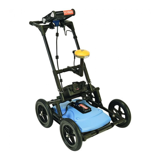
Page 17: Fully Assembled
Assembly 4.3 Fully Assembled The fully assembled RD1500 will look like the following. Simply reverse the directions above to disassemble for transport. RD1500 Operation Manual © Radiodetection 2016... -
Page 18: Section 5 - Getting Started
10% to 0% = red Once the system boots up, you will see the main screen (Figure 5-2). If you have purchased (or upgraded to) the RD1500 Enhanced system, you will see the main screen shown in Figure 5-3. © Radiodetection 2016... - Page 19 Getting Started Figure 5-2: Main Screen for RD1500 Figure 5-3: Main Screen for RD1500 Enhanced The differences between the two configurations are described in Section 3. Everything remains the same in the on-board software, except for in the Enhanced system, where the main screen will allow you to organize data into projects.
-
Page 20: Shutting Down
Saves a screenshot of line data, grid data or the Map View display. Asterisk / Special Function Used for adding Flags during data acquisition, and to quickly enter the No Save mode for Line Scan data collection. © Radiodetection 2016 RD1500 Operation Manual... -
Page 21: Swipe Down Menu
Volume: The Volume + and - buttons are used to increase and decrease speaker volume. Brightness: The Brightness + and - buttons are used to increase and decrease the screen brightness. For example, increasing the Brightness setting may improve the visibility of the screen in bright sunlight. RD1500 Operation Manual © Radiodetection 2016... - Page 22 Getting Started NOTE: Increasing the screen brightness also increases power consumption, thus reducing battery life. To close the Swipe-Down menu, touch anywhere on the screen below the swipe-down menu. © Radiodetection 2016 RD1500 Operation Manual...
-
Page 23: Section 6 - Tools & Setup
Here you can set preferences, adjust system settings, perform system tests and manage files. You will see the screen shown in Figure 6-1: Figure 6-1: Tools menu 6.1 Preferences Selecting the preferences option will take you to the sub-menu shown in Figure 6-2. Figure 6-2: Setting Preferences RD1500 Operation Manual © Radiodetection 2016... -
Page 24: Language
As the name suggests, the notification is completely anonymous and no personal information is sent. 6.2 System Settings Press System Settings to enter the menu shown in Figure 6-3. © Radiodetection 2016 RD1500 Operation Manual... -
Page 25: Date/Time
WiFi Network field. Pressing the WiFi Settings button at the bottom of the screen takes you to a sub-menu (Figure 6-4) for connecting and configuring WiFi settings, as well as setting up an email address. RD1500 Operation Manual © Radiodetection 2016... - Page 26 White = Not connected NOTE: RD1500 CANNOT connect to Public Hotspots, such as those in restaurants, hotels and airports, that require a web-based login and acceptance of Terms & Conditions. It also CANNOT connect to unsecured networks (networks that do not require a password).
- Page 27 Tools & Setup o Setup Email – Saves your Gmail account (email and password) to the RD1500, thereby enabling you to email mini reports from the job site. Before selecting this option: 1. You must be connected to WiFi – a wireless network listed must be green.
-
Page 28: Locale
– buttons to move alphabetically to the next or previous country or region. Press Apply to accept the change and return. Pressing GPS from the System Settings menu takes you to the GPS sub-menu (Figure 6-5). The options displayed in the sub-menu are listed below: © Radiodetection 2016 RD1500 Operation Manual... -
Page 29: Reset To Defaults
Figure 6-5: Reset to Defaults, a) Image on left is the first confirmation screen. b) If you press Yes, you will see the second confirmation screen on the right asking about deleting emails and WiFi settings. RD1500 Operation Manual © Radiodetection 2016... -
Page 30: File Management
Press File Management to enter this sub-menu. From here, the user can view screenshots, export data and delete all data. If you have the regular RD1500, you will see the image in Figure 6-6a. If you have the RD1500 Enhanced system, you will see the image in Figure 6-6b. -
Page 31: Delete All Saved Data
Pressing this will display a map view for all the data (lines & grids) in a given Project (Figure 6- 8). Map View is only enabled if a GPS was on during data collection. Map View shows the RD1500 Operation Manual © Radiodetection 2016... -
Page 32: Export Data
Select the component to test then press Start. After completing a test there is an indication of whether the system passed or failed the test. Each test is described below in more detail. © Radiodetection 2016 RD1500 Operation Manual... -
Page 33: System Information
System Information is the only option in System Test which is not actually a test. Here information such as the version, serial numbers, temperature and battery power is displayed. (Figure 6-10). Figure 6-10: System Information RD1500 Operation Manual © Radiodetection 2016... -
Page 34: Keypad Test
(Figure 6-12). Figure 6-12: Odometer Test. Image on the left shows the screen where the user must select a distance. The image on the right instructs you to move that distance then press Finish. © Radiodetection 2016 RD1500 Operation Manual... -
Page 35: Sensor Test
This test checks proper operation of the GPR sensor, including the amplitude of the pulse. Once the cart is tipped backwards and start is pressed, it will conduct the test (Figure 6-14). If there are any irregularities, the test will indicate failure. Figure 6-14: Sensor Test RD1500 Operation Manual © Radiodetection 2016... -
Page 36: Touch Screen
The GPS test will ensure that the system is communicating properly with the GPS and receiving data. Whichever GPS mode is selected in the System Settings (6.2.3) will be the one used for the test. Pressing GPS will show the screen in Figure 6-16. Figure 6-16: GPS Test © Radiodetection 2016 RD1500 Operation Manual... - Page 37 The user may select this option to verity the GPS is outputting the proper NMEA string format. Figure 6-17: GPS Strings Pressing Clear will clear the strings. Pressing Info will return to the main GPS test menu. RD1500 Operation Manual © Radiodetection 2016...
-
Page 38: Section 7 - Gpr Concepts
The radar wave hits the object before and after going over it and forms a hyperbolic reflection that can appear on the record even though the object is not directly below the radar: © Radiodetection 2016 RD1500 Operation Manual... -
Page 39: Calculating Depth
�� ���� ���������������� �� ���� ��ℎ�� ������ − ������ ������������ �������� For the RD1500, velocity is indicated by the Soil Calibration Value, known as Soil Cal. Once the Soil Cal values are set, the measured depths will be determined accurately (Section 8.6.6) -
Page 40: Air Waves
The best way to identify air reflections is the target hyperbola method. Hyperbolas from above ground objects are wider than objects in the ground and will have a Soil Cal at, or close to, 300. To learn more, see Soil Cal in Section 8.6. © Radiodetection 2016 RD1500 Operation Manual... -
Page 41: Section 8 - Line Scan
Line Scan mode can be used to identify the alignment of subsurface features, check for linearity and acquire accurate depth measurements. If you have the RD1500 Enhanced, ensure you are in the appropriate project before entering this mode. -
Page 42: Selecting A Line
The details of the MapView button are explained in Section 11. Figure 8-2: Line Scan mode, showing a line that was previously collected (a) RD1500 on left, (b) RD1500 Enhanced on right. The RD1500 has the MapView option on this screen. -
Page 43: Dynaq
Figure 8-3: Line Scan acquisition mode, showing collected data and axis labels 8.3 DynaQ™ The RD1500 uses DynaQ, an advanced patented technology that adjusts data quality as the system movement speed varies. In most situations, moving the system at a comfortable walking speed generates data of good quality. -
Page 44: Back-Up Indicator
To locate a feature, simply roll the system back along the same path until the red vertical line is exactly over the response (usually a hyperbola). You can mark the location of the object on the © Radiodetection 2016 RD1500 Operation Manual... -
Page 45: Flags
These markers may help you correlate subsurface targets with above ground features. Pressing the asterisk button on the keypad will insert a flag at your current position, either during forward data acquisition or when backed-up. Flags are sequentially numbered (Figure 8- RD1500 Operation Manual © Radiodetection 2016... -
Page 46: Line Scan Menu Options
10m to 30m (25’ to 100’), see Figure 8-8. One reason for setting this to 30m would be to fit more data on the screen and look for consistency among hyperbolas that were crossed. © Radiodetection 2016 RD1500 Operation Manual... - Page 47 Line Scan Figure 8-7: Varying displayed depth RD1500 Operation Manual © Radiodetection 2016...
- Page 48 Line Scan Figure 8-8: Varying position, or horizontal scaling © Radiodetection 2016 RD1500 Operation Manual...
-
Page 49: Color
However, it will also filter out other flat-lying responses, such as soil boundaries, so be careful when using this option if your target is flat. The filter is set to ON by default. RD1500 Operation Manual © Radiodetection 2016... -
Page 50: Gain
Pressing FrequenSee (or DynaT in some older models) cycles between the options: All, Small, Medium and Large. Each option allows the user to enhance part of the ultra-wide band (UWB) spectrum to focus on those desired features. © Radiodetection 2016 RD1500 Operation Manual... -
Page 51: Soil Cal
Press Soil Cal. The menu at the bottom of the screen will change, giving you the option of either specifying a Soil Type or adjusting the Soil Cal using the hyperbola-fitting method If there are no targets to calibrate to, and you know the type of soil, press: RD1500 Operation Manual © Radiodetection 2016... -
Page 52: Interp
Interpretation (Figure 8-14). This appears as a dot of whatever colour is selected. To change the color, press the Interp button to see a selection of colors and to select a new one (Figure 8-15). © Radiodetection 2016 RD1500 Operation Manual... - Page 53 These field interpretations remain with the data and can be used to check if a feature is linear in Map View or in Google Earth (requires the use of the more accurate external GPS). Figure 8-14: Touching the screen to add Interps Figure 8-15: Available colors for Interps RD1500 Operation Manual © Radiodetection 2016...
-
Page 54: Pause Button (Only Available In No Save Mode)
Drawing arrows (only available in No Save Mode) There is no option for Interps in this mode, as the data is not being saved. However, you do have the ability to draw arrows on the screen (Figure 8-18). © Radiodetection 2016 RD1500 Operation Manual... - Page 55 Just like Interps, any number of arrows can be drawn on this screen. Touch any arrow to remove it. Remember that pressing the Camera button will take a screenshot and save it in the currently selected project. RD1500 Operation Manual © Radiodetection 2016...
-
Page 56: Section 9 - Grid Scan
The screen will change to look like Figure 9-1, which will allow you to set the parameters of the grid, before data acquisition begins. Figure 9-1: Grid Scan setup, from the Enhanced system. On the standard RD1500, it will be the same, except there will not be a project number... -
Page 57: Grid Size
Calculating Resolution The size of target will determine line spacing. The RD1500 must pass over a target to detect it, so line spacing needs to be of the order of the size of the target or smaller when practical. This can be adjusted to a larger spacing for larger targets or targets that are linear. -
Page 58: Data Collection
The data collection screen is shown in Figure 9-3. The right half of the screen is a graphic representation of the grid, illustrating the size of the grid and the lines that need to be collected. The left half of the screen will display the last grid line collected. © Radiodetection 2016 RD1500 Operation Manual... -
Page 59: Recollecting & Skipping Lines
Figure 9-3: Grid data collection screen Press Start when you are positioned at the start of the line. Push the RD1500 in a straight line towards the end of the line. The system knows the length of each line, and will automatically stop acquisition once that distance has been covered. -
Page 60: Processing Data
Once you have finished collecting all the data, press Slice View at the bottom of the screen. The data will be processed and depth slices will be generated. The next Section provides information on using Slice View. © Radiodetection 2016 RD1500 Operation Manual... -
Page 61: Section 10 - Slice View
At the top of the screen, the grid number is listed, along with the slice thickness range. The Soil Cal number was automatically determined when the grid data was processed and is also indicated here. The button functionality is explained below: RD1500 Operation Manual © Radiodetection 2016... -
Page 62: Depth
Setting to LOW will help “clean up” the data and only show the stronger targets, but will hide some of the weak signals so be CAREFUL when setting to LOW. Figure 10-2 shows the variations in color sensitivity © Radiodetection 2016 RD1500 Operation Manual... -
Page 63: Grid Lines
When set to PARTIAL, only some of the grid lines are displayed. This can help identify targets in some larger grids, for example, when having all the grid lines ON may obscure the image beneath (Figure 10-3). RD1500 Operation Manual © Radiodetection 2016... - Page 64 Slice View Figure 10-3: Varying the Grid Lines, from top to bottom: ON, PARTIAL and OFF settings. © Radiodetection 2016 RD1500 Operation Manual...
-
Page 65: Line View
Select the grid line that needs to be recollected. When you press Start, it will display a prompt confirming if you want to overwrite the line. After recollecting the grid line(s), press the Slice View button to re-process the grid data. RD1500 Operation Manual © Radiodetection 2016... -
Page 66: Section 11 - Map View
11.1 Accessing Map View (RD1500) You will only see Map View when you enter either a line or grid Figure 11-1: Accessing Map View from RD1500 11.2 Accessing Map View (RD1500 Enhanced) Map View can be accessed from the File Management menu or from the main screen. -
Page 67: Map View Screen
Map View Figure 11-2: Accessing Map View from RD1500 Enhanced, either from the a) Main screen or b) File Management menu 11.3 Map View screen Irrespective of the system configuration, entering Map View will show an image similar to the one in Figure 11-3. -
Page 68: Section 12 - Capturing Screens And Emailing Mini-Reports
Screenshots can always be emailed at a later time from the Screenshot Gallery (see Screenshot Gallery in Section 6.3 for details). © Radiodetection 2016 RD1500 Operation Manual... -
Page 69: Mini-Reports
When a screenshot is emailed, it is sent as part of a mini-report. This mini-report also contains a table with information about the collected data including the settings used, date and time (Figure 12-3) RD1500 Operation Manual © Radiodetection 2016... - Page 70 Capturing Screens and Emailing mini-reports Figure 12-3: Example of a Mini-Report © Radiodetection 2016 RD1500 Operation Manual...
-
Page 71: Section 13 - Transferring Data To A Pc
Select Yes to transfer immediately. If you select No, you can export the data later by going to the Setup > File Management menu option. RD1500 Operation Manual © Radiodetection 2016... - Page 72 The System Info folder contains log files and a system summary diagnostic report. Each successive export of data will create a new directory called ExportXX, where XX is incremented by 1 from the previous directory. © Radiodetection 2016 RD1500 Operation Manual...
-
Page 73: Section 14 - Troubleshooting
Troubleshooting Section 14 - Troubleshooting The RD1500 system is designed to minimize user problems; however, all electronic devices are subject to possible failure. The following are troubleshooting hints which can be referred to if your system fails to operate. 14.1 Power Supply The most common problem that can occur while trying to run the system is insufficient power. -
Page 74: System Overheating
Troubleshooting 14.3 System Overheating The RD1500 GPR system is designed to operate to a maximum internal temperature of 70ºC or 158ºF. In situations of high ambient temperatures or long exposure to direct sun, this maximum internal temperature may be exceeded and cause the system to fail. -
Page 75: Using The Hotspot On Your Smartphone
Settings - Personal Hotspot. Ensure that the Personal Hotspot setting is turned on, and wait on this screen until the RD1500 connection has been established. Once you have received confirmation on the Display Unit, the cell phone can resume normal use. -
Page 76: Section 15 - Care And Maintenance
Section 15 - Care and Maintenance 15.1 Battery Care The RD1500 uses a 9-Amp-hour, 12-Volt sealed lead acid battery. It is fused with a 10 Amp fuse to protect it from short circuit damage. The battery unit should run the RD1500 continuously for 6 hours before recharging is necessary. If long days of data surveying are typical, a second battery may be useful. -
Page 77: Skid Pads
15.5 Storage Cases Equipment that is transported and stored loosely is more susceptible to damage. All equipment should be stored in its shipping case or a storage box. Radiodetection has optional shipping cases available for all RD1500 systems. RD1500 Operation Manual... -
Page 78: Section 16 - Technical Specifications
Warranty Section 16 - Technical Specifications Specifications Values GPR Sensor size 630 x 410 x 230 mm (25 x 16 x 9 in) GPR Sensor weight 5 kg (11 lbs) Display Unit weight 2.83 kg (6.24 lbs) 8.0" diagonal, high-visibility, sunlight-readable LCD display with touch screen Display Unit screen Adjustable backlighting... -
Page 79: Section 17 - Warranty
Before a unit is submitted for service or repair, under the terms of this warranty or otherwise, any data stored on the unit should be backed-up to avoid any risk of data loss. Radiodetection will not be responsible for loss or erasure of data storage media or accessories. - Page 80 Use of the product with accessories, peripheral equipment and other products of a type, condition and standard other than prescribed by Radiodetection. viii. Repair or attempted repair by persons who are not Radiodetection warranted and certified repair houses. Adjustments or adaptations without Radiodetection’s prior written consent, including: a.
-
Page 82: Section 18 - Appendix A: Health & Safety Certification
Figure A-1: FCC limits for maximum permissible exposure (MPE) plane-wave equivalent power density mW/cm All Radiodetection Ltd GPR products are normally operated at least 1m (3’) from the user and as such are classified as “mobile” devices according to the FCC. Typical power density levels at... - Page 83 Appendix A: Health & Safety Certification is 200 to 10,000 times lower than mandated limits. As such, Radiodetection products pose no health and safety risk when operated in the normal manner of intended use.
-
Page 84: Section 19 - Appendix B: Gpr Emissions, Interference And Regulations
Appendix B: GPR Emissions, Interference and Regulations Section 19 - Appendix B: GPR Emissions, Interference and Regulations Most governments have regulations on the level of electromagnetic emissions that an electronic apparatus can emit. The objective is to ensure that one apparatus or device does not interfere with any other apparatus or device in such a way as to make the other apparatus non- functional. - Page 85 Appendix B: GPR Emissions, Interference and Regulations WARNING Changes or Modifications not expressly approved by the manufacturer could void the user’s authority to operate the equipment. Certification of this equipment has been carried out using approved cables and peripheral devices. The use of non-approved or modified cables and peripheral devices constitutes a Change or Modification outlined in the warning above.
- Page 86 Appendix B: GPR Emissions, Interference and Regulations Subpart F_Ultra-Wideband Operation Sec. 15.525 Coordination requirements. (a) UWB imaging systems require coordination through the FCC before the equipment may be used. The operator shall comply with any constraints on equipment usage resulting from this coordination.
- Page 87 Appendix B: GPR Emissions, Interference and Regulations Effective Date Note: At 68 FR 19751, Apr. 22, 2003, Sec. 15.525 was amended by revising [[Page 925]] paragraphs (b) and (e). This amendment contains information collection and recordkeeping requirements and will not become effective until approval has been given by the Office of Management and Budget.
- Page 88 Appendix B: GPR Emissions, Interference and Regulations FCC GROUND PENETRATING RADAR COORDINATION NOTICE NAME: ADDRESS: CONTACT INFORMATION [ CONTACT NAME AND PHONE NUMBER AREA OF OPERATION [ COUNTIES STATES OR LARGER AREAS FCC ID: QJQ-NG250 EQUIPMENT NOMENCLATURE: NG250 Send the information to: Frequency Coordination Branch, OET Federal Communications Commission 445 12...
- Page 89 OFCOM. (https://licensing.ofcom.org.uk). We recommend that users check with the Radio and Telecoms Licensing authority in the country of use. Radiodetection sales and support staff can help with contact details and information. For those who wish to get more detailed information, they should acquire copies of the following documents available from ETSI.
- Page 90 Appendix B: GPR Emissions, Interference and Regulations B-3a Industry Canada Regulations - English Industry Canada published its regulations for ground penetrating radar (GPR) on Mar 29 2009 as part of the RSS-220 titled 'Devices Using Ultra-Wideband (UWB) Technology'. Industry Canada has made a unique exception for GPR by not requiring user licensing. The user does have to comply with the following directives: This Ground Penetrating Radar Device shall be operated only when in contact with or within 1m of the ground.
- Page 91 Appendix B: GPR Emissions, Interference and Regulations B-3b Règlement d'Industrie Canada - Français Industrie Canada a publié des règlements pour les appareils géoradar (GPR) le 29 mars 2009, dans le cadre du RSS-220 intitulé "Dispositifs utilisant la bande ultra-large (UWB)". Industrie Canada a faite une exception unique pour GPR en n'exigeant pas de licence par utilisateur.
-
Page 92: Section 20 - Appendix C: Instrument Interference
Based on independent testing house measurements, Radiodetection systems comply with such regulations in Canada, USA, European Community and most other jurisdictions. GPR devices can sense electromagnetic fields. -
Page 94: Section 21 - Appendix D: Safety Around Explosive Devices
Concerns are expressed from time to time on the hazard of GPR products being used near blasting caps and unexploded ordnance (UXO). Experience with blasting caps indicates that the power of Radiodetection’s GPR products is not sufficient to trigger blasting caps. Based on a conservative independent testing house analysis, we recommend keeping the GPR transmitters at least 6 feet (2m) from blasting cap leads as a precaution. -
Page 96: Section 22 - Appendix E: Wifi Module
The manufacturer warrants that the RD1500 is not dual-use. - Page 97 United States and/or other countries. Due to a policy of continued development, we reserve the right to alter or amend any published specification without notice. This document may not be copied, reproduced, transmitted, modified or used, in whole or in part, without the prior written consent of Radiodetection Ltd.
Need help?
Do you have a question about the RD1500 and is the answer not in the manual?
Questions and answers