Table of Contents
Advertisement
Quick Links
Advertisement
Table of Contents

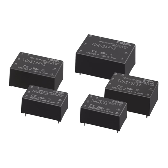
Summary of Contents for Cosel TUHS Series
- Page 1 Applications Manual TUHS series Rev. 1.10E 2019/7/25...
-
Page 2: Table Of Contents
Applications Manual for TUHS series Contents Page 1. Pin Assignment Pin assignment 2. Connection for Standard Use Connection for standard use Input fuse :F1 Smoothing capacitor for input voltage :Cbc Inrush current limiting resistor :R1 Input capacitor (TUHS25) :C1 Varistor :SK1... - Page 3 Applications Manual TUHS series 1 Pin Assignment 2.1 Pin configuration 1.1 Pin Assignment ●TUHS3/TUHS5 ●TUHS10/TUHS15 ●TUHS25 Fig.1.1 Pin Assignment +BC -BC (top view) +BC -BC +BC -BC +Vout +Vout +Vout -Vout -Vout -Vout Table.1.1 Function Connection Pin connection and function...
-
Page 4: Connection For Standard Use
Applications Manual TUHS series 2.1 Pin configuration 2 Connection for Standard Use 2.1 Connection for Standard Use ■ To use the TUHS series, connection shown in Figure 2.1 and external components are required. Fig. 2.1 Connection for Load standard use ■... - Page 5 Applications Manual TUHS series ■ When connect the output to FG of an equipment, a noise may become big. The noise can be reduced by connecting external filter and grounding capacitor on the input side. Refer to Fig2.2. ■ Parts name are shown in Table 2.2 as reference of connecting output to FG.
-
Page 6: Input Fuse :F1
Applications Manual TUHS series 2.2 Input fuse :F1 ■ No protective fuse is preinstalled on the input side. To protect the unit, install a slow-blow type fuse shown in Table 2.2 in the input circuit. ■ In the case of using DC input, please use a DC fuse. - Page 7 Applications Manual TUHS series ■ Electrolytic capacitor has lifetime. So make sure that the lifetime is no problem under the usage condition. ■ Detail formula is different by capacitor manufacturer. When calculating the lifetime, follow the instruction of capacitor manufacturers.
-
Page 8: Inrush Current Limiting Resistor: R1
TUHS series 2.4 Inrush current limiting Resistor: R1 ■ The TUHS series have no internal inrush current limiting circuit. ■ Connect resistor R1 between AC input and power supply to limit inrush current up to 50A(TUHS3/5/10/15) and 60A(TUHS25). Select a resistor which has enough permissible current capability. -
Page 9: Input Capacitor (Tuhs25) :C1
2.7 Output capacitor:Co ■ In the TUHS series, the output capacitor is basically unnecessary. Reduce the ripple voltage or suppress fluctuation in an output voltage by connecting the output electorolytic capacitor or ceramic capacitor. The connection example is shown in Fig 2.7. -
Page 10: Derating
Applications Manual TUHS series 3.Derating 3.1 Output current derating 2.1 Pin configuration 3.1 Output derating ■ Please have sufficient ventilation to keep the temperature of point A in Fig.3.1 at Table 3.1 or below. Please also make sure that the ambient temperature does not exceed 85℃... -
Page 11: Input Voltage Derating
Applications Manual TUHS series (E) TUHS25 Derating curve(Reference) 3.2 Input derating ■ Input derating curve is shown Fig.3.3. In cases that conform with safety standard, input voltage range is AC100-AC240V (50/60Hz) and DC120-DC370V. ■ The operating temperature range, please refer to Section 3.1. -
Page 12: Operation Under Low Temperature Condition
Applications Manual TUHS series 4. Operation Under Low Temperature Conditions 2.1 Pin configuration 4.1 Outline of unstable operation at low temperature and countermeasures ■ At low temperatures, ESR of Cbc and power thermistor become high. At this condition, the output voltage may become unstable due to the voltage drop on the inrush current limiting components and Cbc. - Page 13 Applications Manual TUHS sereis ■ In order to avoid unstable operation, please reduce the input ripple voltage of the BC terminal. Please be three times or more of the recommended capacity in connection permission capacity within the capacity of the Cbc. Please select the capacitor with low ESR and excellent temperature characteristics.
-
Page 14: Holdup Time
Applications Manual TUHS series 5. Hold-up Time, Hold-up Voltage 2.1 Pin configuration 5.1 Hold-up time ■ Hold-up time is determined by the capacitance of Cbc. Fig. 5.1 shows the relationship between hold-up time and load within the allowable capacitance of Cbc. - Page 15 Applications Manual TUHS series (Reference) (Reference) Load factor[%] Load factor[%] Hold-up time Hold-up time TUHS25 (AC100V) TUHS25 (AC200V) 5.2 Hold-up voltage ■ Fig. 5.2 shows the relationship between hold-up voltage and load. These data are the approximate indication for the hold-up voltage.
-
Page 16: Board Layout
Applications Manual TUHS series 6.Board layout 2.1 Pin configuration 6.1 Considerations for component placement and wiring pattern ■ Recommend not wire the high voltage line (AC and +BC voltage) on the surface of the primary components side. ■ The distance between the pattern connected to AC and +BC must be separeted 3mm or more. - Page 17 Applications Manual TUHS series ■ There is the possibility that the significant radiation noise is generated, please connect input smoothing capacitor Cbc to the ± BC terminal as close as possible. ■ If 2 layer or more substrate is used, the radiation noise can be reduced by crossing the output pattern (+Vo, -Vo) as shown in Fig.6.3.
-
Page 18: Reference Pcb Layout
Applications Manual TUHS series 6.2 Reference PCB layout ■ Fig 6.5 (A),(B),(C) shows the reference PCB layout which is used the components listed in Table 2.1. Fig.6.5 Reference PCB layout (Double sided) (A) TUHS3/TUHS5 (B) TUHS10/TUHS15 (C) TUHS25 A-16... - Page 19 Applications Manual TUHS series Revision history date page content 1 2014.5.1 A-2 table2.1 Reference AC Fuse Type Name change 2 2014.5.1 Reference DC Fuse Type name added 3 2014.5.1 But, if the ripple current of ・・・ deleted 4 2014.11.14 1.1 Block Diagram added 5 2014.11.14...


Need help?
Do you have a question about the TUHS Series and is the answer not in the manual?
Questions and answers