Table of Contents
Advertisement
Quick Links
Basic Characteristics Data
Model
Circuit method
CHS60
Foward converter
CHS80
Half-bridge converter
CHS120
Half-bridge converter
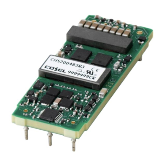
CHS200
Full-bridge converter
CHS300
Full-bridge converter
CHS400
Full-bridge converter
CHS500
Full-bridge converter
*1
Refer to Specification.
*2
Refer to Instruction Manual.
CHS-20
Basic Characteristics Data
Switching
Input
frequency
current
[kHz]
440
*1
250
*1
200
*1
150
*1
170
*1
150
*1
150
*1
Inrush
Rated
current
input fuse
Material
protection
-
-
glass fabric base, epoxy resin
-
-
glass fabric base, epoxy resin
-
-
glass fabric base, epoxy resin
-
-
glass fabric base, epoxy resin
-
-
glass fabric base, epoxy resin
-
-
glass fabric base, epoxy resin
-
-
glass fabric base, epoxy resin
Series/Redundancy
PCB/Pattern
operation availability
Single
Double
Series
sided
sided
operation
Multilayer
Yes
Multilayer
Yes
Multilayer
Yes
Multilayer
Yes
Multilayer
Yes
Multilayer
Yes
Multilayer
Yes
Redundancy
operation
*2
*2
*2
*2
*2
*2
*2
Advertisement
Table of Contents


Need help?
Do you have a question about the CHS60 and is the answer not in the manual?
Questions and answers