Table of Contents
Advertisement
Quick Links
GB
BA No.: 02.09.201/2019-06_A01
Read this User Manual
the user as well as for future use and subsequent sales.
User Manual
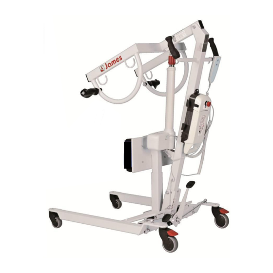
Standing-up Hoist
James 150
320.02.10
.
Art
150 kg
Affix serial number here
before using the device for the first time
®
REBOTEC
Rehabilitationsmittel GmbH
D-49610 Quakenbrück, Artlandstr. 57-59
Telephone: +49 (0) 5431/9416-0
Fax: +49 (0) 5431/9416-66
http://www.rebotec.de
Email: info@rebotec.de
and keep it at hand for
Advertisement
Table of Contents

Subscribe to Our Youtube Channel
Related Manuals for Rebotec James 150


Summary of Contents for Rebotec James 150
- Page 1 Fax: +49 (0) 5431/9416-66 BA No.: 02.09.201/2019-06_A01 http://www.rebotec.de Email: info@rebotec.de User Manual Standing-up Hoist James 150 320.02.10 150 kg Affix serial number here Read this User Manual before using the device for the first time and keep it at hand for...
-
Page 2: Table Of Contents
REBOTEC / BA No.: 02.09.201/2019-06_A01 Description of the device Installing the column Installing the linear drive Installing the holder with knee pro- tection Connecting the electrical system Charging the rechargeable battery Connecting & charging Charge level & control display Display symbols... -
Page 3: Degrees Of Protection
REBOTEC / BA No.: 02.09.201/2019-06_A01 For ordering spare parts and processing Meaning complaints, the device name, serial num- No protection ber and year of manufacture will be re- Protection against vertically falling drops quired. of water Protection against vertically falling drops... -
Page 4: Warranty
REBOTEC / BA No.: 02.09.201/2019-06_A01 EMERGENCY OFF function and a rechargeable Weight loads must not be hung onto the forked battery unit. arm for an extended period of time. This rechargeable battery unit allows the device to be used independently of an external energy... -
Page 5: Disposal
REBOTEC / BA No.: 02.09.201/2019-06_A01 5. Disposal 7.2. Installing the control unit Insert the two clamps of the cable holder into the support. The local disposal regulations must be complied with. Please contact a disposal company for further information. 6. Scope of delivery The device has been carefully inspected in the factory for freedom from defects. -
Page 6: Installing The Column
REBOTEC / BA No.: 02.09.201/2019-06_A01 Then slide the control unit with the lower guide (2) over the remaining screw. Remove the packaging material afterwards. Then screw the screw back in again in pos. 3. Tighten the screw hand-tight. 7.4. Installing the linear drive... -
Page 7: Tection Connecting The Electrical System
REBOTEC / BA No.: 02.09.201/2019-06_A01 7.6. Connecting the electrical system Insert the flat plug of the charging cable in the con- Insert the plug of the linear drive in the jack (1). trol unit (3) and then secure it using the cable clip Please pay attention to the positioning of the re- (4). -
Page 8: Display Symbols
REBOTEC / BA No.: 02.09.201/2019-06_A01 8.3. Display symbols: As an alternative, the linear drive can also be ex- tended (lifted) using the button (1) on the control unit and retracted (lowered) with the electrical Symbols Description emergency lowering (2). See 12.1. -
Page 9: Mechanical Emergency Lowering
REBOTEC / BA No.: 02.09.201/2019-06_A01 12.2. Mechanical emergency lowering Spread apart If the patient becomes exposed to an emergency Press the right side of the pedal. situation, an electrical defect occurs at the drive motor, the control unit fails or the rechargeable bat- tery is completely discharged, it is necessary to use the mechanical emergency lowering. -
Page 10: Technical Data
(acids, benzene, thinners) or stiff Depending on the application, there are several dif- cleaning tools (brushes). ferent types of sling systems offered by REBOTEC. Otherwise, this may result in damage to the metal To assist you in selecting the most suitable sling surface or deposits on the metal parts and other system, a Guide is available (see 19.). -
Page 11: Scope Of Maintenance
Never make any unauthorised modifications or conversions to the device. These will only ad- versely affect the safety and functioning of the device. In such cases, REBOTEC will not as- sume any product liability. Follow all the instructions for ordering spare parts, reuse and the lifetime of the device. -
Page 12: Spare Parts & Accessories
REBOTEC / BA No.: 02.09.201/2019-06_A01 19. Spare parts & accessories 5a/b - 12 -... - Page 13 Handles for D22x120mm column 420.58.97 SL24/1.5 key ring 420.00.14 Screwing set for centre of rotation 320.60 Handles for Standing-up Hoist James Use only REBOTEC spare parts and accessories to ensure the proper and safe functioning of the device. - 13 -...
-
Page 14: Drawing & Dimensions
REBOTEC / BA No.: 02.09.201/2019-06_A01 20. Drawing & dimensions - 14 -... - Page 15 REBOTEC / BA No.: 02.09.201/2019-06_A01 James 150 Dimensions No. Designation in mm Highest point Highest point at highest reach Lowest point Highest reach at a height of 600 mm (reference height) Highest reach from the base frame Reach from the base frame when expanding the leg supports to 700 mm...
- Page 16 D-49610 Quakenbrück, Artlandstr. 57-59 Telephone: +49 (0) 5431/9416-0 Fax: +49 (0) 5431/9416-66 http://www.rebotec.de Email: info@rebotec.de Read this User Manual before using the device for the first time and keep it at hand for the user as well as for future use and subsequent sales.
Need help?
Do you have a question about the James 150 and is the answer not in the manual?
Questions and answers