Bosch RA1181 Operating/Safety Instructions Manual
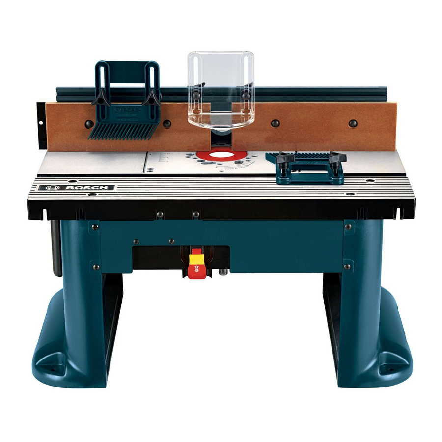
Bosch power tools router - bench-top router table user manual
Hide thumbs
Also See for RA1181:
- User manual ,
- Operating/safety instructions manual (100 pages) ,
- User manual (34 pages)
Table of Contents
Advertisement
Available languages
Available languages
IMPORTANT:
IMPORTANT :
IMPORTANTE:
Read Before Using
Lire avant usage
Leer antes de usar
Operating/Safety Instructions
Consignes de fonctionnement/sécurité
Instrucciones de funcionamiento y seguridad
RA1181
Consumer Information
Renseignement des consommateurs
Información para el consumidor
Toll Free Number:
Appel gratuit :
Número de teléfono gratuito:
1-877-BOSCH99 (1-877-267-2499) http://www.boschtools.com
For English
Parlez-vous français?
¿Habla español?
See page 2
Voir page 32
Ver página 64
2 610 927 748 09/05
Advertisement
Table of Contents

Subscribe to Our Youtube Channel
Related Manuals for Bosch RA1181


Summary of Contents for Bosch RA1181
- Page 1 Read Before Using Lire avant usage Leer antes de usar Operating/Safety Instructions Consignes de fonctionnement/sécurité Instrucciones de funcionamiento y seguridad RA1181 Consumer Information Renseignement des consommateurs Información para el consumidor Toll Free Number: Appel gratuit : Número de teléfono gratuito: 1-877-BOSCH99 (1-877-267-2499) http://www.boschtools.com...
-
Page 2: Power Tool Safety Rules
IMPORTANT SAFETY INFORMATION . . .2–5 Parts List ......6–9 Read and understand the tool manual and these instructions for the use of this table with your router. - Page 3 Do not force tool. Use the correct tool for your application. The correct tool will do the job better and safer at the rate for which it is designed. Do not use tool if switch does not turn it “ON” or “OFF.”...
- Page 4 Additional Safety Warnings for Router Tables Piloted bits along with the starter pin are used when routing internal and external contours on the workpiece. Use the auxiliary bit guard when shaping material with the starter pin and piloted bits. The starter pin and bearing of the piloted bit assist in maintaining control of the workpiece.
- Page 5 IMPORTANT: Some of the following symbols may be used on your tool. Please study them and learn their meaning. Proper interpretation of these symbols will allow you to operate the tool better and safer. Symbol Name Volts Amperes Hertz Watt Kilograms Minutes Seconds...
-
Page 6: Parts List
• If ANY of the parts are missing, DO NOT attempt to assemble, install, or use your router table until the missing parts have been found or replaced and your router table has been properly and correctly assembled per this manual. •... - Page 7 Parts List Router Table Assembly Starter Pin Assembly Tabletop Inserts Fence Assembly Featherboard...
- Page 8 FASTENERS (FOR TABLE ASSEMBLY) #10-32 KEPS Nut #10-32 ESNA Stop Nut 1/4-20 KEPS Nut 9/32″ ID x 5/8″ OD x 1/16″ Thick Washer #10-32 x 1″ Pan-Head Phillips Machine Screw #10-32 x 3/4″ Countersunk Socket-Head Screw #10-32 x 3/4″ Truss-Head Phillips Machine Screw ″...
- Page 9 Parts List (33) #10-32 x 5/8″ Countersunk Phillips Machine Screw ″ Carriage Bolt (31) 1/4-20 x 1 ⁄ (34) 1/4-20 x 1″ Carriage Bolt (32) 1/8″ Hex Key (Allen Wrench) ″ Pan-Head ⁄ (37) #10-24 x 3/4″ Pan-Head (35) #10-32 x 3/4″ Pan-Head (36) 1/4-20 x 1 Phillips Machine Screw Phillips Machine Screw...
-
Page 10: Router Table Assembly
2. Assemble the legs (6) to the router table as shown in the figure. 3. Assemble a 9/32″ ID x 5/8 OD″ x 1/16″ thick washer (27) and a 1/4-20 KEPS nut (26) onto each of the bolts. 4. Securely tighten the fasteners. - Page 11 ATTACH THE SWITCH TO THE FASCIA (FIG. 3) 1. Align the two outermost holes on the top of the switch assembly (10) with the holes in the front fascia panel (9), as shown in Fig. 3. 2. Insert two #10-32 KEPS nuts (24) into the hex-shaped recesses in the back of the switch assembly (10), toothed side out, and secure the switch to the fascia panel with two #10-32 x 3/4″...
-
Page 12: Assembling The Fence
ASSEMBLING THE FENCE (Figs. 5 and 6) 1. Insert the pins molded into the top of the vacuum port (13) into the holes on the rear of the aluminum fence (11), as shown in Fig. 5. 2. From the underside of the fence, insert two #10-32 x 5/8″... -
Page 13: Tools Required
INSTALLING THE ROUTER MOUNTING PLATE TOOLS REQUIRED • 1/8″ Allen wrench (32) (included) • Phillips screwdriver (not included) • Straight edge (not included) • Small-sized adjustable wrench (not included) NOTE: The fences must NOT be installed on the router table for the following procedures. PRELIMINARY INSTALLATION OF THE ROUTER MOUNTING PLATE (Figs. -
Page 14: Mounting Plate Guide For Compatible Routers
BEFORE USING THE ROUTER TABLE, REFER TO THE ROUTER OWNER’S MANUAL FOR OPERATION INFORMATION. SELECTING THE ROUTER HOLE PATTERN DETERMINE THE MOUNTING METHOD TO BE USED (see chart on page 15) If your router model is listed in the chart on page 15, proceed to step 1 below. -
Page 15: Mounting Method Determination Chart
CHART 1 Router Router Brand Model Bosch 1613 series Bosch 1617 series (fixed base models only) Bosch 1619EVS Craftsman Most Craftsman 1/2″ collet routers DeWalt DW616, DW618 (fixed base only) Hitachi M12VC Makita RF1100, RF1101 Milwaukee 5615, 5616 Porter Cable 690 series, 7529 plunge router, and 892–895 series... - Page 16 FINAL INSTALLATION OF THE ROUTER MOUNTING PLATE (Fig. 11) 1. Place the router mounting plate, with router attached, on the leveling screws in the tabletop. NOTE: Be careful not to trap the cord between the router mounting plate and the router tabletop. 2.
-
Page 17: Installing The Fence
(31) up through the slots in the tabletop and the holes in the bottom of the fence. Slide a washer (27) onto each bolt and loosely attach a large clamping knob (14) onto each bolt. 2. Make sure that the fence assembly slides smoothly from front to back. - Page 18 MOUNTING THE ROUTER TABLE TO A WORK SURFACE OR WORKBENCH Before operating, make sure the entire unit (table with router installed) is placed on and secured to a solid, flat, level surface and will not tip. Use of auxiliary in-feed and out-feed sup- ports is necessary for long or wide workpieces.
- Page 19 METHOD 2 (Fig. 14) 1. Set the router table on a workbench or other stable and sturdy surface, with the FRONT (switch side) of the router table facing toward you. 2. Secure the router table legs to the workbench with clamps, making sure to tighten them SECURELY.
- Page 20 ALWAYS MAKE SURE THAT THE ROUTER IS TURNED OFF AND THE POWER CORD IS UNPLUGGED BEFORE MAKING ANY ADJUSTMENTS. TABLETOP INSERTS (Fig. 16) This router table includes three tabletop inserts with the following hole sizes: • 1″ in diameter (3), for use with bits with diameters up to 7/8″...
-
Page 21: Router Table Operation
ELECTRICAL REQUIREMENTS A 14 gauge (or heavier) three-wire extension cord with a three-hole grounding receptacle and three-hole grounding plug is to be used for connecting the switch to an electrical outlet. DAMAGED OR WORN EXTENSION CORDS ARE NOT TO BE USED AND ARE TO BE REPLACED IMMEDIATELY. -
Page 22: Switch Operation
ON (RESET) With the lockout key in place and the cover raised, the switch can be toggled to the ON (RESET) position. Note that the red slide panel is fully retracted from the switch. CONNECTING THE ROUTER POWER CORD TO THE SWITCH •... - Page 23 BEFORE PROCEEDING ANY FURTHER, MAKE SURE THE SWITCH ON THE ROUTER IS IN THE OFF POSITION AND THE SWITCH LEVER IS IN THE OFF POSITION. The switch power cord can now be plugged into the extension cord. MAKE SURE THAT POWER CORDS FROM THE ROUTER, ACCESSORIES, THE SWITCH CASE, AND THE EXTENSION CORD DO NOT AND CANNOT COME IN CONTACT WITH THE...
- Page 24 ⁄ through the slotted holes in the featherboard (19). See Fig. 18. 2. Slide a large washer (27) onto each carriage bolt and thread a small clamping knob (17) three or four turns onto each carriage bolt. 3. To install on the fence, slide a spacer (16) over the head of each carriage bolt, aligning the tabs on the spacer with the slot in the featherboard (Fig.
- Page 25 ROUTING USING FEATHERBOARDS (Fig. 21) Featherboards are helpful in controlling the workpiece while routing and assist in keeping the workpiece flat on the tabletop. The table featherboard, combined with the fence featherboard, helps keep the workpiece pressed against the fence and tabletop. The best location for the featherboards varies according to your application, workpiece size, and other factors.
- Page 26 ADJUSTING DEPTH AND HEIGHT OF CUT (Fig. 23) 1. Select a board that is smooth and straight, with good square edges. 2. Mark lines “A” and “B” on the end of the board, as shown in Detail 23. • Line “A” indicates the desired height of cut. •...
- Page 27 FULL EDGE CUTTING OR JOINTING (Figs. 24 and 25) For maximum strength and accuracy, boards that are to be joined together should be smooth and true. The edges should be true to the workpiece surface. You can true the edges using the router table with a straight bit.
- Page 28 EDGE CUTTING WITH NONPILOTED ROUTER BITS (Figs. 26 and 27) ALWAYS MAKE SURE THAT THE ROUTER IS TURNED OFF AND THE POWER CORD IS UNPLUGGED BEFORE MAKING ANY ADJUSTMENTS. NOTE: If the jointing shim is installed, remove it before proceeding. When using nonpiloted router bits, the fence is used to set the depth of cut.
- Page 29 EDGE CUTTING WITH PILOTED ROUTER BITS (Figs. 28 and 29) ALWAYS MAKE SURE THAT THE ROUTER IS TURNED OFF AND THE POWER CORD IS UNPLUGGED BEFORE MAKING ANY ADJUSTMENTS. NOTE: If the jointing shim is installed, remove it before proceeding. 1.
- Page 30 GROOVING, FLUTING, AND VEINING (Figs. 30 and 31) ALWAYS MAKE SURE THAT THE ROUTER IS TURNED OFF AND THE POWER CORD IS UNPLUGGED BEFORE MAKING ANY ADJUSTMENTS. NOTE: If the jointing shim is installed, remove it before proceeding. When performing these routing operations, the use of featherboards and a push shoe is recommended.
- Page 31 USING THE STARTER PIN FOR EDGE FORMING OF CURVES The starter pin (20) is used instead of the fence for operations that involve routing curves in the workpiece. It should be used only with bits that have pilot bearings. Thread the starter pin into the threaded hole in the mounting plate and tighten securely with a slotted screwdriver (Fig.
-
Page 32: Consignes De Sécurité
CONSIGNES DE SÉCURITÉ IMPORTANTS ....32–35 Liste de pièces ....36–39 Consignes de sécurité... - Page 33 Consignes de sécurité générales concernant les outils électriques Débranchez la fiche de l’outil avant d’effectuer un réglage, de changer d’accessoire ou de ranger l’outil. De telles mesures préventives de sécurité réduisent le risque de mise en marche accidentel de l’outil. Laissez les gardes en place.
- Page 34 N’utilisez jamais votre table comme établi ou surface de travail. Si vous l’utilisez pour faire autre chose que travailler à la toupie, vous risquez d’occasionner des dommages et de rendre sont utilisation dangereuse. Des fraises pilotées et la goupille de démarrage sont utilisés pour travailler sur les contours internes et externes de la pièce.
- Page 35 Important : Certains des symboles suivants peuvent être utilisés sur votre outil. Veuillez les étudier et apprendre leur signification. Une interprétation appropriée de ces symboles vous permettra d’utiliser l'outil de façon plus efficace et plus sûre. Symbole Volts Ampères Hertz Watt Kilogrammes Minutes...
-
Page 36: Liste De Pièces
Référez-vous à la liste de pièces ci-dessous et aux pages 37 à 39. • Si l’une ou l’autre pièce est manquante, N’essayez PAS d’assembler, d’installer ou d’utiliser votre table à toupie avant que les pièces manquantes aient été retrouvées ou remplacées et que votre table à... - Page 37 Ensemble de la table Ensemble du guide Liste de pièces Ensemble de goupille de démarrage Bagues du dessus de la table Guide biseauté...
- Page 38 Rep. Description ATTACHES FOURNIS (Pour l’assemblage de la table) Écrou «KEPS» n Écrou de blocage ESNA n Écrou «KEPS»1/4-20 Rondelle 9/32 po D.I. x 5/8 po D.E. x 1/16 po Vis à métaux Phillips à tête ronde n Vis à métaux Allen à tête fraisée n Vis à...
- Page 39 Liste de pièces (33) Vis à métaux Phillips à tête fraisée 10-32 x 5/8 po (34) Boulon de carrosserie (31) Boulon de carrosserie 1/4-20 x 1 po 1/4-20 x 1 ⁄ (32) Clé Hex 1/8 po (Clé Allen) (37) Vis à métaux Phillips à tête (36) Vis à...
- Page 40 Assemblage de la table à toupie ASSEMBLAGE DE LA TABLE À TOUPIE PIÈCES RAPPORTÉES POUR PATTES DE TABLE : (FIG. 1) La table à toupie comporte deux pièces rapportées pour pattes de table. • Panneau de rangement de patte (7), pour faciliter le rangement des accessoires •...
- Page 41 Assemblage de la table à toupie FIXEZ L’INTERRUPTEUR AU TABLEAU DE BORD (FIG. 3) 1. Alignez les deux trous les plus éloignés en haut de l’ensemble d’interrupteur (10) aux trous du tableau de bord (9), comme l’indique la figure 3. 2.
- Page 42 Assemblage de la table à toupie ASSEMBLAGE DU GUIDE (Figs. 5 et 6) 1. Insérez les taquets moulés sur l’orifice d’aspiration (13) dans les trous en la derrière du guide en aluminium (11) comme l’indique la figure 5. 2. En partant du bas du guide, insérez deux vis à tête noyée n 10-32 x 5/8 po (33) afin qu’ils atteignent les trous situés en bas du guide d’onglets et de l’entrée...
- Page 43 Assemblage de la table à toupie INSTALLER LA PLAQUE DE MONTAGE DE LA TOUPIE UTILS REQUIS (NON COMPRIS) • Clé Allen (32) (comprise avec la table à toupie) • Tournevis Phillips • Règle droite • Petite clé réglable REMARQUE : Les cloisons NE doivent PAS être instal- lées sur la table à...
- Page 44 AVANT D’UTILISER VOTRE TABLE À TOUPIE, CONSULTEZ VOTRE MANUEL DU PROPRIÉTAIRE DE TOUPIE POUR VOIR CHOIX DU SCHÉMA DE TROUS DE LA TOUPIE DÉTERMINEZ LA MÉTHODE DE MONTAGE À UTILISER (VOIR LE TABLEAU À LA PAGE 45) Si le modèle de votre toupie figure dans le tableau de la page 45, passez à...
-
Page 45: Montage
Assemblage de la table à toupie TABLEAU 1 Marque de Modèle de toupie toupie Bosch série 1613 Bosch série 1617 (bases fixes uniquement) Bosch 1619EVS Craftsman Plupart de toupies Craftsman avec de 1/2 po DeWalt DW616, DW618 (base fixe uniquement) Hitachi M12VC Makita... - Page 46 Assemblage de la table à toupie FIXATION DE LA PLAQUE DE MONTAGE DE LA TOUPIE (Fig. 11) 1. Placez la plaque de montage de la toupie, avec la toupie attachée, aux vis de mise à niveau du haut de la plaque. REMARQUE : Faites attention de ne pas coincer le cor- don entre la plaque de montage de la toupie et le haut de la table de toupie.
- Page 47 FIXEZ LE GUIDE À LA TABLE (Fig. 12) 1. Par-dessous, inserez deux boulons de carrosserie 1/4-20 x 1 ⁄ po (31) à travers les deux trous dans le guide et fixez-les avec une grande rondelle (27) et un gros bouton de serrage (14) sur chacun. 2.
- Page 48 Assemblage de la table à toupie FIXER LA TABLE À TOUPIE À UNE SURFACE DE TRAVAIL OU À UN ÉTABLI Avant la mise en marche, assurez-vous que l’ensemble de l’appareillage (la table sur laquelle a été installée la toupie) est placé...
- Page 49 Assemblage de la table à toupie MÉTHODE 2 (FIG. 14) 1. Placez la table à toupie sur un établi ou toute autre surface stable et solide, l’AVANT (côté interrupteur) face à vous. 2. Fixez les pattes de la table à toupie à l’établi avec des serre-joints, en vous assurant de les serrer FERMEMENT.
- Page 50 Assemblage de la table à toupie ASSUREZ-VOUS TOUJOURS QUE LA TOUPIE EST À L’ARRÊT ET QUE LE CORDON DE RALLONGE EST DÉBRANCHÉ AVANT D’EFFECTUER TOUT RÉGLAGE. BAGUES DU DESSUS DE LA TABLE (FIG. 16) Cette table à toupie comprend trois bagues du dessus de la table ayant des trous dont les diamètres intérieurs sont les suivants : •...
- Page 51 Fonctionnement de la table à toupie MODE D’EMPLOI DE L’INTERRUPTEUR SÉCURITÉ ÉLECTRIQUE Vous devez utiliser un cordon rallonge trifilaire de calibre no 14 (ou supérieur) muni d’une prise avec terre à trois trous et d’une fiche de mise à la terre à trois broches pour raccorder l’interrupteur à...
- Page 52 Fonctionnement de la table à toupie RENSEIGNEMENTS GÉNÉRAUX RENSEIGNEMENTS GÉNÉRAUX L’interrupteur est conçu pour être utilisé avec la plupart L’interrupteur est conçu pour être utilisé avec la plupart des tables à toupie de BOSCH. Placé à la portée de la des tables à...
-
Page 53: Fonctionnement De L'interrupteur
Fonctionnement de la table à toupie ARRÊT MARCHE (remise en marche) La clé de sécurité étant en place et le clapet soulevé, on peut faire basculer l’interrupteur à la position MARCHE (REMISE EN MARCHE). Veuillez remarquer que la glissière rouge est totalement en retrait de l’interrupteur. - Page 54 Fonctionnement de la table à toupie AVANT DE POURSUIVRE, ASSUREZ-VOUS QUE LES DEUX INTERRUPTEURS (CELUI DE LA TOUPIE ET CELUI DE L’INTERRUPTEUR) SONT À LA POSITION ARRÊT. Vous pouvez maintenant raccorder le cordon d’alimentation de l’interrupteur au cordon rallonge. ASSUREZ-VOUS QUE LES CORDONS D’ALIMENTATION DE LA TOUPIE, DES ACCESSOIRES, DE L’INTERRUPTEUR ET DES CORDONS RALLONGES NE SONT PAS, NI NE...
- Page 55 Fonctionnement de la table à toupie INSTALLER UN ASPIRATEUR AVALE-TOUT INSTALLATION D’UN ASPIRATEUR AVALE-TOUT AU PORT D’ASPIRATEUR L’assemblage protecteur/port pour aspirateur permet de brancher un tuyau d’aspirateur avale-tout pourvu d’une lance de boyaux de 2 ⁄ po. Pour attacher, poussez la lance dans le port tout en maintenant la cloison en place.
- Page 56 Fonctionnement de la table à toupie ASSEMBLAGE DES GUIDES BISEAUTÉS (Figs. 18–20) REMARQUE : le haut et l’avant de chaque guide à biseaute est marqué pour indiquer la bonne direction d’alimentation. Guide biseauté du guide (Figs. 18 et 19) 1. Insérez deux boulons de carrosserie 1/4-20 x 1 (31) dans les fentes du guide biseauté...
- Page 57 Fonctionnement de la table à toupie TOUPILLAGE À L’AIDE DES GUIDES BISEAUTÉS (Fig. 21) Les guides biseautés sont très utiles pour contrôler la pièces à toupiller et aident à conserver la pièce à plat sur l’établi. Le guide biseauté de la table, combiné au guide biseauté...
- Page 58 Fonctionnement de la table à toupie RÉGLAGE DE LA PROFONDEUR ET DE LA HAUTEUR DE LA COUPE (Fig. 23) 1. Choisissez une planche qui est lisse et droite, avec des bords bien carrés. 2. Marquez les lignes A et B au bout de la planche, comme illustré...
- Page 59 Fonctionnement de la table à toupie COUPE EN BORD OU ASSEMBLAGE (Figs. 24 et 25) Pour un maximum de solidité et de précision, les planches qui doivent être assemblées doivent être lisses et d’équerre. Les bords devraient être d’équerre avec les surfaces de la pièce à travailler. Vous pouvez dresser les bords en utilisant la table à...
- Page 60 Fonctionnement de la table à toupie COUPE EN BORD AVEC DES FRAISES DE TOUPIE NON-PILOTÉE (Figs. 26 et 27) ASSUREZ-VOUS TOUJOURS QUE LA TOUPIE EST À L'ARRÊT ET QUE LE CORDON D’ALIMENTATION EST DÉBRANCHÉ AVANT D’EFFECTUER TOUT RÉGLAGE. REMARQUE : si la cale d’assemblage est installée, retirez-la avant de continuer.
- Page 61 Fonctionnement de la table à toupie COUPE EN BORD AVEC DES FRAISES DE TOUPIE À AVANT-TROU (Figs. 28 et 29) ASSUREZ-VOUS TOUJOURS QUE LA TOUPIE EST À L'ARRÊT ET QUE LE CORDON D’ALIMENTATION EST DÉBRANCHÉ AVANT D’EFFECTUER TOUT RÉGLAGE. REMARQUE : si la cale d’assemblage est installée, retirez-la avant de continuer.
- Page 62 Fonctionnement de la table à toupie RAINURAGE, GOUGEAGE ET NERVURAGE (Figs. 30 et 31) ASSUREZ-VOUS TOUJOURS QUE LA TOUPIE EST À L'ARRÊT ET QUE LE CORDON D’ALIMENTATION EST DÉBRANCHÉ AVANT D’EFFECTUER TOUT RÉGLAGE. REMARQUE : si la cale d’assemblage est installée, retirez-la avant de continuer.
- Page 63 Fonctionnement de la table à toupie UTILISATION DE LA GOUPILLE DE DÉMARRAGE POUR LA FORMATION La goupille de démarrage (20) est utilisée au lieu de la cloison pour les opérations qui nécessitent la taille des profils courbes de la pièce. Elle doit être utilisée seulement avec les fraises qui possèdent des paliers pilotes.
-
Page 64: Instrucciones Importantes
INSTRUCCIONES IMPORTANTES DE SEGURIDAD ....64–68 Lista de piezas ....69–74 Normas de seguridad para herramientas mecánicas Lea y entienda el manual de se fresador y estas instrucciones. -
Page 65: De Seguridad
Normas de seguridad para herramientas mecánicas No intente alcanzar demasiado lejos. Mantenga un apoyo de los pies y un equilibrio adecuados en todo momento. El apoyo de los pies y el equilibrio adecuados permiten un mejor control de la herramienta en situaciones inesperadas. Utilice gafas de seguridad (protección para la cabeza): Utilice gafas de seguridad (deben cumplir con el estándar Z87.1 de ANSI) en todo momento. - Page 66 Las fresadoras están diseñadas para trabajar con madera, productos similares a la madera y plásticos o laminados, mas no para cortar o dar forma a metales. Cerciórese de que la pieza de trabajo no contenga puntillas o clavos, etc. Cortar puntillas o clavos puede provocar una pérdida del control. No utilice brocas que tengan un diámetro de corte que supere el espacio libre en el inserto superior de la mesa.
- Page 67 Importante: Es posible que algunos de los símbolos siguientes se usen en su herramienta. Por favor, estúdielos y aprenda su significado. La interpretación adecuada de estos símbolos le permitirá utilizar la herramienta mejor y con más seguridad. Símbolo Nombre Volts Ampere Hertz Watt...
-
Page 68: Lista De Piezas
Informaciónes importantes sobre los cables de extension Si es necesario un cable de extensión, se debe usar uno con conductores de tamaño adecuado que sea capaz de transportar la corriente necesaria para la herramienta. Esto evitará caídas de tensión excesivas, pérdida de potencia o el recalentamiento. Las herramientas conectadas a tierra deben usar cables de extensión de 3 hilos que tengan enchufes de 3 terminales y receptáculos para 3 terminales. - Page 69 Lista de piezas Ensamblado de la mesa de fresado Pata de arranque Insertos de la superficie de la mesa Ensamblado de la guía Tabla de biselado...
- Page 70 Clave No. Descripción SUJETADORES (Para el ensamblado de la mesa de fresado) Tuerca KEPS #10-32 Tuerca ESNA #10-32 Tuerca KEPS 1/4-20 Arandela 9/32″ D.I. x 5/8″ D.E. x 1/16″ Tornillo de máquina Phillips #10-32 x 1″ Tornillo de cabeza hueca embutida #10-32 x 3/4″ Tornillo de máquina Phillips de cabeza segmental #10-32 x 3/4″...
- Page 71 Lista de piezas (33) Tornillo de máquina Phillips embutido #10-32 x 5/8″ ″ (34) Perno de carruaje (31) Perno de carruaje 1/4-20 x 1 ⁄ 1/4-20 x 1″ (32) Llave hexagonal de 1/8″ (Llave Allen) (37) Tornillo de máquina Phillips (36) Tornillo de máquina Phillips (35) Tornillo de máquina Phillips ″...
-
Page 72: Montaje De La Mesa De Fresado
MONTAJE DE LA MESA DE FRESADO INSERTOS DE LAS PATAS DE LA MESA (FIG. 1) La mesa de fresado incluye dos insertos para las patas de la mesa: • Panel de almacenamiento para la mesa de las patas (7) • Panel de envoltura del cable de las patas (8) Se deben instalar los insertos de las patas de la mesa antes de unir la parte superior de la mesa. - Page 73 Montaje de la mesa de fresado UNA EL INTERRUPTOR A LA FASCIA (FIG. 3) 1. Alinee los dos orificios más extremos en la parte superior de la ensembladura del interruptor (10) con los orificios en el panel delantero de la fascia (9), como se muestra en la Figura 3.
- Page 74 CÓMO ARMAR LA GUÍA (FIGS. 5 y 6) 1. Inserte los pasadores moldeados en la parte superior del puerto de vacío (13) dentro de los orificios en la parte posterior de la guía de aluminio (11) como se muestra en la Figura 5. 2.
- Page 75 CÓMO INSTALAR LA PLACA DE MONTAJE DE LA FRESADORA HERRAMIENTAS NECESARIAS (no incluidas) • Llave Allen (32) (incluida con la mesa de fresado) • Destornillador de estrella • Borde recto • Llave ajustable pequeña NOTA: Las guías NO se deben instalar en la mesa de fresado para los siguientes procedimientos.
- Page 76 ANTES DE USAR LA MESA DE FRESADO, CONSULTE EL MANUAL DEL PROPIETARIO DE LA FRESADORA PARA INFORMACIÓN SOBRE LA OPERACIÓN. CÓMO ELEGIR EL PATRÓN DE ORIFICIOS DE LA FRESADORA DETERMINE EL MÉTODO DE MONTAJE A USAR (vea la tabla en la página 77) Si su modelo de fresadora aparece en la página 77, siga el paso 1 a continuación.
- Page 77 TABLA 1 Marca de Modelo de fresadora fresadora Bosch Serie 1613 Bosch Serie 1617 (bases fijas únicamente) Bosch 1619EVS Craftsman Más fresadoras Craftsman con portabroca de 1/2″ DeWalt DW616, DW618 (base fija únicamente) Hitachi M12VC Makita RF1100, RF1101 Milwaukee 5615, 5616 Porter Cable Serie 690 fresadora de superficie...
- Page 78 INSTALACIÓN FINAL DE LA PLACA DE MONTAJE DE LA FRESADORA (FIG. 11) 1. Coloque la placa de montaje de la fresadora, con la fresadora unida, sobre los tornillos niveladores en la superficie de la mesa. NOTA: Tenga cuidado de no atrapar el cable entre la placa de montaje de la fresadora y la superficie de la mesa de fresado.
- Page 79 CÓMO SUJETAR LA GUÍA A LA MESA (FIG. 12) 1. Desde la parte inferior, coloque dos pernos de carruaje ″ (31) a través de los orificios de la guía, de 1/4-20 x 1 ⁄ y ajústelos con una arandela grande (27) y una perilla de fijación grande (14).
- Page 80 CÓMO MONTAR LA MESA FRESADORA A UNA SUPERFICIE O BANCO DE TRABAJO Antes de operar, cerciórese de que toda la unidad (mesa con fresadora instalada) se coloque y se asegure en una superficie sólida, plana, a nivel y que no se incline. Para piezas de trabajo largas o anchas, utilice soportes auxiliares de ali- mentación hacia dentro y hacia fuera.
- Page 81 MÉTODO 2 (FIG. 14) 1. Fije la mesa de fresado en una banca de trabajo u otra superficie estable y fuerte, con el FRENTE (lado del interruptor) de la mesa de fresado hacia usted. 2. Asegure las patas de la mesa de fresado a la banca de trabajo con presillas, asegurándose de apretarlas FIRMEMENTE.
- Page 82 SIEMPRE CERCIÓRESE DE QUE LA FRESADORA ESTÉ APAGADA Y QUE EL CABLE ELÉCTRICO ESTÉ DESCONECTADO ANTES DE HACER CUALQUIER AJUSTE. ENCASTRES DE LA SUPERFICIE DE LA MESA (FIG. 16): Esta mesa de fresado viene con tres encastres de la superficie de la mesa, en los tamaños de agujero siguientes: •...
-
Page 83: Requisitos Eléctricos
Operación de la mesa de fresado INSTRUCCIONES PARA EL INTERRUPTOR REQUISITOS ELÉCTRICOS Un cable de extensión de calibre 14 (o superior) de tres hilos con un receptáculo de conexión a tierra de tres orificios y un enchufe con conexión a tierra de tres orificios se deben usar para conectar el interruptor a una toma eléctrica. -
Page 84: Información General
Operación de la mesa de fresado INFORMACIÓN GENERAL El interruptor eléctrico está diseñado para uso con la mayoría de las mesas de fresado BOSCH. Brinda la conveniencia de un interruptor de ON/RESET (encendido/ reiniciar)- OFF (apagado) al frente de la mesa, eliminando así la necesidad de alcanzar por debajo de la mesa para encender o apagar la fresadora. - Page 85 Operación de la mesa de fresado ON (RESET) Con la llave de seguridad en su lugar y la tapa levantada, se puede desplazar el interruptor a la posición ON (RESET). Nótese que el panel de deslizamiento rojo se encuentra completamente retirado del interruptor.
- Page 86 Operación de la mesa de fresado ANTES DE SEGUIR ADELANTE, CERCIÓRESE DE QUE EL INTERRUPTOR EN LA FRESADORA ESTÉ EN LA POSICIÓN DE APAGADO Y LA PALANCA DEL INTERRUPTOR ESTÉ EN LA POSICIÓN DE APAGADO. El cable eléctrico del interruptor se puede conectar en este momento en el cable de extensión.
- Page 87 Operación de la mesa de fresado CÓMO INSTALAR UNA ASPIRADORA SECA/HÚMEDA INSTALACÍON UNA ASPIRADORA SECA / HÚMEDA El conjunto de recolección de polvo/tapa tiene un puerto para conectar una manguera de aspiración húmeda / seca ″. Para unirla, simplemente con una boquilla de 2 ⁄...
- Page 88 Operación de la mesa de fresado CÓMO ARMAR LA LAS TABLAS DE BISELADO (FIGS. 18–20) NOTA: El costado superior/ delantero de cada tabla de biselado está marcada para indicar la dirección correcta de alimentación. Tabla de biselado de la guía (Figs. 18 y 19) 1.
- Page 89 Operación de la mesa de fresado CÓMO FRESAR UTILIZANDO TABLAS DE BISELADO (FIG. 21) Las tablas de biselado son de utilidad para controlar la pieza de trabajo mientras se realiza el trabajo de fresado, y sirven para mantener la pieza de trabajo plana sobre la mesa.
- Page 90 Operación de la mesa de fresado CÓMO AJUSTAR LA PROFUNDIDAD Y LA ALTURA DEL CORTE (FIG. 23) 1. Seleccione una tabla suave y recta, con buenos bordes cuadrados. 2. Marque las líneas “A” y “B” en el extremo de la tabla, como aparece en el detalle 23.
- Page 91 Operación de la mesa de fresado CORTE O UNIÓN DEL BORDE COMPLETO (FIGS. 24 y 25) Para una mayor fuerza y exactitud, las tablas a unirse deben estar lisas y cuadradas. Los bordes deben estar alineados con las superficies de la pieza de trabajo. Se pueden nivelar los bordes mediante el uso de una mesa de fresado con una broca recta.
- Page 92 Operación de la mesa de fresado CORTE DE LOS BORDES CON BROCAS DE FRESADO NO PILOTEADAS (FIGS. 26 y 27) SIEMPRE CERCIÓRESE DE QUE LA FRESADORA SE APAGUE Y EL CABLE ELÉCTRICO ESTÉ DESCONECTADO ANTES DE HACER CUALQUIER AJUSTE. NOTA: Si la cuña de empalme se encuentra instalada, retírela antes de comenzar a trabajar.
- Page 93 Operación de la mesa de fresado CORTE DE LOS BORDES CON BROCAS DE FRESADO PILOTEADAS (FIGS. 28 y 29) SIEMPRE CERCIÓRESE DE QUE LA FRESADORA SE APAGUE Y EL CABLE ELÉCTRICO ESTÉ DESCONECTADO ANTES DE HACER CUALQUIER AJUSTE. NOTA: Si la cuña de empalme se encuentra instalada, retírela antes de comenzar a trabajar.
- Page 94 Operación de la mesa de fresado RANURAS, ACANALADURAS Y VETAS (FIGS. 30 y 31) SIEMPRE CERCIÓRESE DE QUE LA FRESADORA SE APAGUE Y EL CABLE ELÉCTRICO ESTÉ DESCONECTADO ANTES DE HACER CUALQUIER AJUSTE. NOTA: Si la cuña de empalme se encuentra instalada, retírela antes de comenzar a trabajar.
- Page 95 Operación de la mesa de fresado USO DE LA PATA DE ARRANQUE PARA FORMAR LOS BORDES DE LAS CURVAS La pata de arranque (20) se utiliza en vez de la guía para las operaciones que involucran el fresado de curvas en la pieza de trabajo.
- Page 96 © Robert Bosch Tool Corporation, 1800 W. Central Road, Mt. Prospect, IL 60056-2230 Exportado por: Robert Bosch Tool Corporation, Mt. Prospect, IL 60056-2230, E.U.A. Importado en México por: Robert Bosch, S.A. de C.V., Calle Robert Bosch No. 405, Zona Industrial, Toluca, Edo.
Need help?
Do you have a question about the RA1181 and is the answer not in the manual?
Questions and answers