Endress+Hauser Micropilot NMR81 Functional Safety Manual
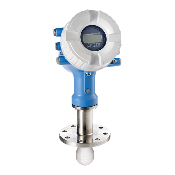
Free space radar for liquids with output signal 4...20 ma and switch output
Hide thumbs
Also See for Micropilot NMR81:
- Manual (272 pages) ,
- Operating instructions manual (260 pages) ,
- Brief operating instructions (56 pages)

Related Manuals for Endress+Hauser Micropilot NMR81


Summary of Contents for Endress+Hauser Micropilot NMR81
- Page 1 Products Solutions Services SD01891G/00/EN/03.18 71413288 2018-08-10 Special Documentation Micropilot NMR81/84 Functional Safety Manual Free space radar for liquids with output signal 4...20 mA and switch output...
-
Page 2: Table Of Contents
Micropilot NMR81/84 Table of contents Declaration of Conformity ....3 Other safety-related characteristic values ... . . -
Page 3: Declaration Of Conformity
Micropilot NMR81/84 Declaration of Conformity A0037370 Endress+Hauser... -
Page 4: Other Safety-Related Characteristic Values
Micropilot NMR81/84 A0037371 Other safety-related Characteristics as per IEC 61508 Value characteristic values MTBF 25 years System reaction time as per DIN EN 61508-2 In "Expert mode": User configurable According to Siemens SN29500. This value takes into account failure types relevant to the function of the electronic components. -
Page 5: Useful Lifetime Of Electric Components
Micropilot NMR81/84 Useful lifetime of electric The established failure rates of electrical components apply within the useful lifetime as per IEC 61508-2:2010 section 7.4.9.5, note 3. In accordance with DIN EN 61508-2:2011 section components 7.4.9.5, national footnote N3, appropriate measures taken by the manufacturer and operator can extend the useful lifetime. -
Page 6: Document Information
• General information about functional safety: SIL • General information about SIL is available: In the Download Area of the Endress+Hauser Internet site: www.de.endress.com/SIL Using this document Information on the document structure For the arrangement of the parameters as per the Operation menu, Setup menu, Diagnostics... -
Page 7: Supplementary Device Documentation
Micropilot NMR81/84 Supplementary device Documentation Comment documentation Technical Information: The documentation is available on the Internet: • TI01252G/00 (NMR81) → www.endress.com • TI01253G/00 (NMR84) Operating Instructions The documentation is available on the Internet: • BA01450G/00 (NMR81) → www.endress.com • BA01453G/00 (NMR84) Brief Operating Instructions (HART): •... -
Page 8: Permitted Devices Types
Micropilot NMR81/84 Permitted devices types The details pertaining to functional safety in this manual relate to the device versions listed below and are valid as of the specified software and hardware version. Unless otherwise specified, all subsequent versions can also be used for safety instrumented systems. . A modification process according to IEC 61508 is applied for device changes. -
Page 9: Sil Label On The Nameplate
Micropilot NMR81/84 Order code * All options are possible. (This selection does not affect SIL capability.) • Valid firmware version: as of 01.02.zz or 01.03.zz (→ nameplate of the device) • Valid hardware version (electronics): as of date of production 23.11.2016 (→ nameplate of the... -
Page 10: Restrictions For Use In Safety-Related Applications
Micropilot NMR81/84 Restrictions for use in safety- • The measuring system must be used correctly for the specific application, taken into account the medium properties and ambient conditions. Pay attention to the information concerning critical related applications process situations and installation conditions in the Operating Instructions/Technical Information. - Page 11 Micropilot NMR81/84 Dangerous undetected failures in this scenario A dangerous, undetected failure is considered to be an incorrect output signal that deviates from the real value by more than 2 %, wherein the output signal is still in the range of 4 to 20 mA or the relay contact remains closed.
-
Page 12: Use In Protective Systems
Micropilot NMR81/84 Use in protective systems Device behavior during Digital operation Device behavior during power-up Once switched on, the device runs through a diagnostic phase of approx. 30 seconds. The relay contact is open during this time. During the diagnostic phase, no communication is possible via the service interface (CDI) or via protocols (HART, V1, Modbus). -
Page 13: Parameter Configuration For Safety-Related Applications
Micropilot NMR81/84 Alarm and warning messages Additional information is provided by the alarm and warning messages in the form of error codes and associated clear text messages. The following table shows the correlation between the error code and the current output:... - Page 14 Micropilot NMR81/84 Setting • Alarm mode = On • Alarm value source = Tank level (depending on the source) • HH alarm value, H alarm value, L alarm value and LL alarm value must be configured in line with the application such that the valid range is within the HH, H and L, LL limits.
- Page 15 Micropilot NMR81/84 Configuration method When using the devices in process control safety systems, the device configuration must comply with two requirements: • Confirmation concept: Proven, independent testing of safety-related parameters entered. • Locking concept: Locking of the device following parameter configuration (IEC 61511-1: 2016 Section 11.6.3).
- Page 16 Micropilot NMR81/84 Set write protection = Enter the locking code again (SIL: 7452). Check the locking status after performing SIL locking. Navigate to: Setup → Advanced setup Locking status = SIL locked must be confirmed by selecting "". As an option, hardware locking can also be activated (via the dip switch marked "WP" on the main electronics).
- Page 17 Micropilot NMR81/84 Further parameter settings The following parameters affect the safety function. However, they may be freely configured in accordance with the application: It is recommended to note down the configured values! Parameter Parameter name Setup → Advanced setup → Sensor config...
- Page 18 Micropilot NMR81/84 Select the sequence "Setup → Advanced setup → Deactivate SIL/WHG" and enter the corresponding unlocking code (SIL: 7452) for the Reset write protection parameter. The "End of sequence" message indicates that the device was successfully unlocked. Endress+Hauser...
-
Page 19: Proof-Testing
Micropilot NMR81/84 Proof-testing Check the operativeness and safety of safety functions at appropriate intervals! The operator must determine the time intervals. The values and graphics in the "Additional safety-related characteristics" section can be used for this purpose → 4. The test must be carried out in such a way that it verifies the correct operation of the protective system in interaction with all of the components. - Page 20 Micropilot NMR81/84 Test sequence A (approach the level) Preparation Level limit value monitoring and range monitoring can also be performed when the SIL mode is active. If the safety-related "Analog" signal is used, loop a suitable measuring device (recommended accuracy better than ±0.1 mA) into the installed circuit.
- Page 21 Micropilot NMR81/84 Set: Output simulation = Simulating inactive. 10. Check whether the contact is closed (resistance <1 Ω) between contacts Xy and Xz. 11. Set: Output simulation = Fault 2. 12. Check whether the contact is open (resistance >1 MΩ) between contacts Xy and Xz.
- Page 22 Micropilot NMR81/84 Test sequence B (simulate the level) Preparation Deactivate SIL mode. Navigate to: Setup → Advanced setup → Deactivate SIL/WHG and enter the corresponding unlocking code (SIL: 7452) for the Reset write protection parameter. If the safety-related "Analog" signal is used, connect a suitable measuring device (recommended accuracy better than ±0.1 mA) in the installed circuit.
- Page 23 Micropilot NMR81/84 Deactivate SIL mode. Navigate to: Setup → Advanced setup → Deactivate SIL/WHG and enter the corresponding unlocking code (SIL: 7452) for the Reset write protection parameter. Perform the device self-check as follows. Navigate to: Setup → Advanced setup Set: Input/output = Digital Xy-z Check whether Contact type = Normally closed (SIL factory setting).
- Page 24 Micropilot NMR81/84 Test sequence C (simulation and single-point level detection) Preparation Deactivate SIL mode. Navigate to: Setup → Advanced setup → Deactivate SIL/WHGand enter the appropriate unlocking code (SIL: 7452) for the "Reset write protection" parameter parameter. If the safety-related "Analog" signal is used, connect a suitable measuring device (recommended accuracy better than ±0.1 mA) in the installed circuit.
- Page 25 Micropilot NMR81/84 POWER A0032388 Deactivate SIL mode. Navigate to: Setup → Advanced setup → Deactivate SIL/WHG and enter the appropriate unlocking code (SIL: 7452) for the Reset write protection parameter parameter. Perform the device self-check as follows. Navigate to: Setup → Advanced setup → Input/output →...
- Page 26 Micropilot NMR81/84 Test sequence D (feed in real currents) Preparation Level limit value monitoring and range monitoring can also be performed when the SIL mode is active. If the safety-related "Analog" signal is used, connect a suitable measuring device (recommended accuracy better than ±0.1 mA) in the installed circuit.
- Page 27 Micropilot NMR81/84 Check whether the contact is open (resistance >1 MΩ) between contacts Xy and Xz. Set: Output simulation = Simulating inactive. 10. Check whether the contact is closed (resistance <1 Ω) between contacts Xy and Xz. 11. Set: Output simulation = Fault 2.
-
Page 28: Life Cycle
Micropilot NMR81/84 Life cycle Requirements for personnel The personnel for installation, commissioning, diagnostics, repair and maintenance must meet the following requirements: • Trained, qualified specialists must have a relevant qualification for this specific function and task • Are authorized by the plant owner/operator •... -
Page 29: Repairs
Installation Instructions, see the Download Area at www.endress.com. The replaced component must be sent to Endress+Hauser for the purpose of fault analysis if the device has been operated in a protective system and a device error cannot be ruled out. In this case, always enclose the "Declaration of Hazardous Material and Decontamination"... -
Page 30: Appendix
Structure of the measuring System components system The measuring system' s devices are displayed in the following diagram (example): NXA820 A0032451 Micropilot NMR81, NMR84 4 to 20 mA line Switch output Fieldbus (e.g. Modbus, V1) Tankvision Tank Scanner NXA820 Ethernet Computer with Fieldcare Logic Unit, e.g. - Page 31 Micropilot NMR81/84 Typical measuring arrangement A0032453 Datum plate: reference point of the measurement 4 mA, 0 % L or LL alarm H or HH alarm 20 mA, 100 % The device can be used in this arrangement in safety instrumented systems for MIN safety, MAX safety and range monitoring.
-
Page 32: Proof-Testing
Micropilot NMR81/84 Proof-testing System-specific data Company Measuring point/TAG no. Facility Device type/Order code Serial number of device Name Date Access code (if individual to each device) Locking code used 7452 Signature Device-specific commissioning parameters Tube diameter (liquid measurement; pipe/bypass) - Page 36 *71413288* 71413288 www.addresses.endress.com...
Need help?
Do you have a question about the Micropilot NMR81 and is the answer not in the manual?
Questions and answers