
Related Manuals for Jomox ModBase 09 MkII


Summary of Contents for Jomox ModBase 09 MkII
- Page 1 Version OS 2.07 ModBase 09 MkII Euro-Rack Analog Kick Drum Synthesizer Module Operating Manual ModBase 09 MkII Operating Manual...
-
Page 2: Table Of Contents
5. Sound parameters (menu orange/red)..........17 5.1. LFO.....................17 5.1.1. LFO 1 Wave < SuP / Sdo / Sin / Si- / tri / tr- / rCt / rC- >....17 5.1.2. LFO 1 Speed < 000-252 >............18 ModBase 09 MkII Operating Manual... - Page 3 6.5. Volume < 000-255 > ..............26 6.6. Bus Env < 000-255 >..............26 6.7. Fine Tune CV (hidden) < 000-255 >..........26 6.8. Store...................26 7. ModBase 09 MkII Midi implementation..........27 7.1. SysEx Dump................27 7.1.1. Single preset dump..............27 7.1.2. All presets dump..............27 7.1.3. Receive SysEx dump..............27 7.2.
-
Page 4: Introduction
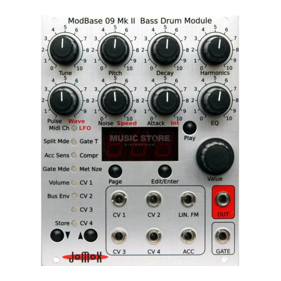
Version OS 2.07 Introduction Thanks for using the JoMoX ModBase 09 MkII! The ModBase 09 MkII is a great sounding, dedicated kick drum module with a real analog sound production made for installation in 19 inch euroracks as offered by companies like Doepfer GmbH for instance. -
Page 5: Installation
Version OS 2.07 1. Installation Please turn off the euro rack prior to the wiring! On the backside of the ModBase 09 MkII module you can find these connections: ModBase 09 MkII Operating Manual... -
Page 6: Installation In The Eurorack
Volts and the CV/Gate on the A-100 Doepfer bus are both not wired inside the Jomox modules and not needed. Other 10 pin systems may be used as well if only the lower part of the 16 pin connector is connected. Please pay... - Page 7 Don't flip the cable but connect it as shown on the picture. Then please mount the module on the rack rails with the supplied metric M3 screws. In case you want to connect a midi cable, please do this beforehand of mounting. ModBase 09 MkII Operating Manual...
-
Page 8: Midi In
Version OS 2.07 1.1. Midi In Here you can hook up another midi device to control the ModBase 09 MkII by either a software sequencer, a controller box or any other hardware device like e.g. a JoMoX XBase09, XBASE999/888. Please use a cable that is as short as possible. -
Page 9: Front Connections
The inputs CV1-CV4 are programmable CV control inputs. In a modular system, most functions and parameters like eg. VCO pitch or filter cutoff can be controlled by a CV (control voltage). In the ModBase 09 MkII, practically all internal sound parameters can be controlled (ie. modulated) by an assignable CV. -
Page 10: Acc
The gate input of a typical modular environment is the input which is used to trigger the tone of the ModBase 09 MkII. The typical gate high signals used in modular world have normally 5-15 volts, which the gate input of the ModBase 09 MkII can process without any problems –... -
Page 11: General Functions
3.1. Preset selection < P00-P99 > As long none of the 8 menu LEDs is lighting, the ModBase 09 MkII is in preset mode. Now you can choose one of 100 preprogrammed presets by turning the value input wheel. The sounds get loaded automatically. -
Page 12: Midi Control
3.3.1. Note trigger The ModBase 09 MkII processes midi note commands. It can be triggered by any midi sequencer. If the ModBase 09 MkII receives midi data on the selected channel, the leftmost decimal point in the display lights up. Please find the settings of the various midi functions in chapter 7 Midi Implementation. -
Page 13: Parameter Control Via Midi Controllers
This is the default trigger mode on the ModBase09 II. Please connect a typical modular gate/trigger CV sequencer (like eg. the Doepfer A-155) to the Gate jack. The ModBase 09 MkII processes gate signals from 0..1 volts to 0..15 volts. To get retriggered, the signal must at least once drop below the trigger threshold, which is a little below 1 volts. -
Page 14: Sound Parameters (Potentiometers)
If you don't want sound paramers to be changed by unwanted knob movements, press <Edit/Enter> again to leave the edit mode. The ModBase 09 MkII has a dedicated potentiometer knob for the 8 most important parameters. Some sound parameters are only being changed via the LED menu and the incremental wheel though. -
Page 15: Tune < 000-252
VCA. The sound of the pulse is strongly affected by the gate time (see also Gate Time) which determines the “energy” of the pulse and therefore the frequency spectrum of the first attack. ModBase 09 MkII Operating Manual... -
Page 16: Noise < 000-252
EQ. On the ModBase 09 MkII, the sound of the noise signal is significantly affected by parameters 5.4 MetNze 1 + 2 because the noise can be assembled by metallic high pitch tones. -
Page 17: Sound Parameters (Menu Orange/Red)
LFO 1. The value is shown in the display. LFO 1 always works firmly on the pitch of the kick drum. With the LFO (Low Frequency Oscillator) you can produce periodic low frequency pitch modulations (vibrato). ModBase 09 MkII Operating Manual... -
Page 18: Lfo 1 Speed < 000-252
Turn Potentiometer 7 (Noise, Int) to edit the intensity of LFO 1. The value is shown in the display. LFO 1 always works on the pitch of the kick drum. LFO 1 Intensity controls the amount of modulation. Zero turns the modulation off. ModBase 09 MkII Operating Manual... -
Page 19: Lfo 1 Destination
This menu serves to initialize a preset. If you turn the data wheel to the right, all sound parameters are changed to the default value. The display shows “ini“ then. Attention! If you didn't store the sound before, all settings are gone. ModBase 09 MkII Operating Manual... -
Page 20: Compr(Ression) (Page Red) < 000-255
Hint: The noise signal is only audible during the gate period of the attack and is strongly affected by the gate time and EQ filtering. By tweaking these parameters you can modulate the attack of the kick drum very fine and precisely. ModBase 09 MkII Operating Manual... -
Page 21: Metnze 2 (Page Red) < Off-499
The CV inputs are able to modulate a wide variety of sound parameters. The inputs process voltages from 0..5 volts and can be assigned to a list of modulation targets. Furthermore, the modulation amount can be adjusted for every CV individually and can be negative too. ModBase 09 MkII Operating Manual... -
Page 22: Cv 1-4 Destination
Display Function Realtime mod. Tune Envelope Bass Drum Pitch Decay Harmonics Pulse Noise Attack EQ-Filter Compression Metallic Noise 1 Metallic Noise 2 LFO 1 Rate LFO 1 Intensity LFO 2 Rate LFO 2 Intensity Preset Number ModBase 09 MkII Operating Manual... -
Page 23: Cv 1-4 Amount (Page Red) <-128 - 127
CV range 0..5 volts. Example: if the amount is = 50 , then maximum CV 5 volts = preset 50 and thus 2.5 volts = preset 25, 1 volts = preset 10 asf. ModBase 09 MkII Operating Manual... -
Page 24: Master Parameters (Menu Green)
6. Master parameters (menu green) 6.1. Midi Ch(annel) < 001 - 016 > Midi channel on which the ModBase 09 MkII receives and transmits Midi data. Received are: note on/off, note number, program change, controllers. Transmitted are: note on/off, note number, program change. -
Page 25: Acc Dynamics < D01- D63
In position “PoS“ = positive (default), the signal must rise from 0 to at least 1.5 volts in order to properly trigger the ModBase 09 MkII. After that, the gate signal has to fall again under the threshold down to 0 volts to be able to trigger again. -
Page 26: Volume < 000-255
Version OS 2.07 6.5. Volume < 000-255 > Adjusts the main volume of the ModBase 09 MkII. The maximum velocity of incoming midi notes get only processed to this level. For the best sounding results, you should keep it at <255>. -
Page 27: Modbase 09 Mkii Midi Implementation
MkII. Now press record at the connected midi device (we strongly recommend the newest Jomox SysEx Dumper tool). Then press the Play button on the ModBase 09 MkII. The current active preset is sent as a midi dump. 7.1.2. All presets dump Please select the empty menu 7 (Menu LED 7 green) at the ModBase 09 MkII. -
Page 28: Sound Parameter Cc
0..127 MetalNze II 0..15 Mask Volume 0..127 LFO 1 Wave 0..15 Sup/Sdo/Sin/Si-/tri/tri-/r Ct/rC-/PL1-PL8 LFO 1 Intensity 0..127 LFO 1 Speed 0..127 LFO 2 Wave 0..15 Sup/Sdo/Sin/Si-/tri/tri-/r Ct/rC-/PL1-PL8 LFO 2 Intensity 0..127 LFO 2 Speed 0..127 ModBase 09 MkII Operating Manual... -
Page 29: Note Commands
One line of system exclusive commands looks like the following: $F0(SysEx Begin), $31(JoMoX Manufact. code), $7F(Command Sys Ex Dump), $5e(Product Code), $XX(Preset No.),XX(Data0),XX(Data1),..., $F7(End of SysEx) 32 bytes [bit7...bit0] (0..255) of data per preset are transferred. They are split into two 7-bit midi bytes: MSB [bit7] in Data0 and LSB [bit6...bit0] in Data1.
Need help?
Do you have a question about the ModBase 09 MkII and is the answer not in the manual?
Questions and answers