
Related Manuals for Yale SDA16


Summary of Contents for Yale SDA16
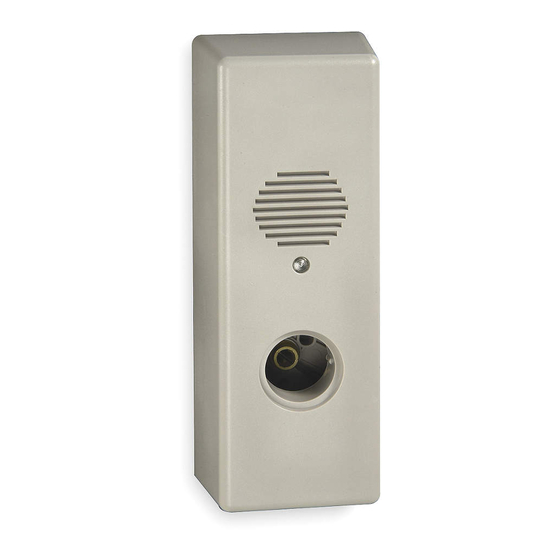
- Page 1 SDA16 Stand-Alone Alarm Device Installation Instructions EMERGENCY EXIT - ALARM WILL SOUND 80-9470-0330-000 (01-13) An ASSA ABLOY Group brand...
- Page 2 1. Frame and Door Preparation In-swinging Door Out-swinging Door 1. For installation on an In-swinging Door, mark a 1. For installation on an Out-swinging Door, Vertical Reference Line 1-15/16"(50mm) off of the mark a Vertical Reference Line 2-3/16"(56mm) Frame Edge, also decide the vertical placement and off of the Frame Stop, also decide the vertical mark a Horizontal Reference Line.
- Page 3 2. Installing Cylinder 3. Device Handing Change 1. Remove (2) screws retaining the magnet sensor 1. Insert mortise cylinder through hole in the Housing. and set components aside. 2. Orient keyway to the 6 o’clock position, adjust as needed. 2. Remove (2) screws retaining the Tamper Switch and exchange locations of both components (See Figure 5).
-
Page 4: Standard Installation
Refer to Page 5 for Alarm Function Adjustments Before proceeding with Step 4 4. Standard Installation 5. Hardwire Installation Note: Hardwire options require wire harness within the door or 1. After preparing the door, attach the Mounting Base wall and may require door position switches (DPS) or other means to door through holes “A”... - Page 5 ALARM FUNCTION AS SHIPPED * The unit is shipped with power disconnected, attach battery connector as shown below. 1) Upon arming, LED will flash AMBER and the device will allow egress without triggering alarm for 7 seconds. 2) After 7 seconds, alarm will chirp one time and the device will be ARMED. The LED will flash RED every 30 seconds, indicating the device is ARMED.
-
Page 6: Troubleshooting
Yale Locks & Hardware is a division of Yale Security Inc., an ASSA ABLOY Group company. Yale® is a registered trademark of Yale Security Inc., an ASSA ABLOY Group company. Other products' brand names may be trademarks or registered trademarks of their respective owners and are mentioned for reference purposes only. - Page 7 Device Template Vertical (In-Swinging Door) Reference Line 1-15/16" (50) DOOR “D” Frame Edge (Do Not Fold) 1/2" (13) (Ref) .144 Dia. #27 Drill Locate off of edge to clear swing 1" Dia. of door (25) 3-3/4" (95) “C” 3/8" 3/8" (10) (10) 1-1/4"...
- Page 8 Device Template Vertical Reference (Out-Swinging Door) DOOR Line 1/16" 3/16" (Ref.) “D” Frame Edge 2-3/16" (Fold Line) (56) .144 Dia. #27 Drill 1" Dia. (25) 3-3/4" (95) “C” Magnet and 3/8" Cylinder located 3/8" (10) on same centerline (10) 1-1/4" (Arrow on Magnet (32) Dia.
Need help?
Do you have a question about the SDA16 and is the answer not in the manual?
Questions and answers