Table of Contents
Advertisement
Quick Links
Advertisement
Table of Contents

Related Manuals for Benewake CE30-D


Summary of Contents for Benewake CE30-D
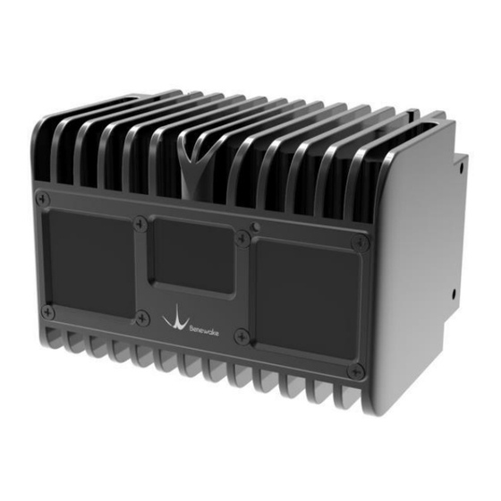
- Page 1 CE30-D Solid-State Array LiDAR Operation Manual Page 1...
- Page 2 The Copyright of this document is protected. All the rights involved herein belong to Benewake (Beijing) Co., Ltd. Any copy activity of this document, no matter in whole or in part, should be in conformity of the Copyright Law. The actives of modification, omission or translation of this document are not allowed unless a written permission from Benewake (Beijing) Co., Ltd.
-
Page 3: Table Of Contents
Benewake(Beijing)Co., Ltd CE30-D Product Manual - V04 Table of Contents 1. CE30-D introduction.......................... 4 2. Operation of Display Program......................4 2.1 Connection............................5 2.2 Display program window......................6 3. Coordinate transformation......................... 7 4. Indicator Instruction........................... 7 5. Line sequence descriptions........................ 8 6. -
Page 4: Ce30-D Introduction
At the top, bottom, left, right and back, CE30-D has mounting location holes provided, through which it can be fixed with peripheral devices reliably. See Figure 1 for the positions and spacing of the mounting holes subject to the size of M3. -
Page 5: Connection
Ethernet Power Figure 3 CE30-D aerial plug wiring instructions a. Use the two aerial plug cables attached in the package (including one power supply plug cable and one network port plug cable) to connect the LiDAR with the aerial plug cables as illustrated in Figure 3;... -
Page 6: Display Program Window
Benewake(Beijing)Co., Ltd CE30-D Product Manual - V04 If it prompts as shown in Figure 6, it indicates that the LiDAR is working normally with the data connection available. If no, it indicates that the data link suffers from ping failures. Please check as follows: a) Check whether the indicators light up on the front panel of the LiDAR and whether the red lamp keeps normally on and flashing after startup;... -
Page 7: Coordinate Transformation
Windows interface. 3. Coordinate transformation The CE30-D outputs distance and angle by polar coordinates. In order to facilitate the reconstruction and application of 3D point cloud image, they can be transformed into rectangular coordinate system by the X = Dist ×... -
Page 8: Line Sequence Descriptions
Benewake(Beijing)Co., Ltd CE30-D Product Manual - V04 Indicator Figure 8 Indicator position 1) Blue normally on: In the “Ready” state, it can be connected to work. 2) Blue flashing: It is working. 3) Red flashing: The relevant run files are missing. -
Page 9: Test Instruction And Description
Benewake(Beijing)Co., Ltd CE30-D Product Manual - V04 Front interface Installation platform Figure 10: Recommendation for LiDAR installation. The LiDAR front interface must extrude from (at least be aligned to) the front plane of the installation platform; otherwise, the data accuracy will be lower due to interference. -
Page 10: Vertical Angle Resolution
Figure 12 CE30-D's detecting area Vertical Angle Resolution CE30-D has 20 lines in vertical direction, and the vertical angle resolution is 0.2 degree, so that CE30-D has more precise resolution capacity. The detection angle in vertical direction is presented in Table 1. -
Page 11: Interference Of Ambient Light
Benewake(Beijing)Co., Ltd CE30-D Product Manual - V04 Interference of Ambient light LiDAR can work at ambient light with 60klux intensity, but the error increases compared with indoor situation. The error in different testing conditions is presented in Figure 13. Figure 13 Comparison of indoor and outdoor Error Note: The figure only show the error within 17m. -
Page 12: Influence Factors Of Measurement
Benewake(Beijing)Co., Ltd CE30-D Product Manual - V04 Figure 14 Dist Error varies with external Temp at different distance 8. Influence Factors of Measurement Multi Optical Path Based on ToF LiDAR principle, if there are multiple echo regions as shown in the figure below at the working height of the radar, the multi-path phenomenon will be triggered: the LiDAR receives the light returned by the path 1 and the path 2 at the same time, which may result in a larger measurement value. -
Page 13: Multi Distance Objects
Benewake(Beijing)Co., Ltd CE30-D Product Manual - V04 As shown below, when solid-state ToF LiDAR is working, in addition to the light reflected by the object 1, the light scattered by object 2 and object 3 that close to the LiDAR will enter the lens. Such stray light can lead to a deviation of the object 1’s ranging. - Page 14 Benewake(Beijing)Co., Ltd CE30-D Product Manual - V04 Q2: From the manual, the power supply is DC 12V ± 0.5V (≥3A),and power consumption is 8w. So how much is the working current? A2: The normal working current is lower than 0.65A when radar working normally. There will be relatively high pulse current when radar is detecting distance, the peak of pulse current is lower than 3A.
Need help?
Do you have a question about the CE30-D and is the answer not in the manual?
Questions and answers