Sign In
Upload
Download
Table of Contents
Contents
Add to my manuals
Delete from my manuals
Share
URL of this page:
HTML Link:
Bookmark this page
Add
Manual will be automatically added to "My Manuals"
Print this page
×
Bookmark added
×
Added to my manuals
Manuals
Brands
Mecc Alte Manuals
Portable Generator
ECO43 Series
Installation, use and maintenance manual
Mecc Alte ECO43 Series Installation, Use And Maintenance Manual
Self-regulatig alteriators
Hide thumbs
1
2
Table Of Contents
3
4
5
6
7
8
9
10
11
12
13
14
15
16
17
18
19
20
21
22
23
24
25
26
27
28
29
30
31
32
33
34
35
36
37
38
39
40
41
42
43
44
45
46
47
48
49
50
51
52
53
54
55
56
57
58
59
60
61
62
63
64
65
66
67
68
69
70
71
72
73
74
75
76
77
78
79
80
81
82
83
84
85
86
87
88
89
90
91
92
93
94
95
96
97
98
99
100
101
102
103
104
105
106
107
108
109
110
111
112
113
114
115
116
page
of
116
Go
/
116
Contents
Table of Contents
Bookmarks
Table of Contents
Table of Contents
Respinsibility if the User
Warranty
Geieral Iiformatoi
After-Sales Assistance
Infirmatin Required Ti Ibtain After-Sales Assistance
Addressees if the Manual
Machine Identicatin Details
Figure 1- Data Plate Example
Table 1 - Generatir Plate Data
Descriptin if the Priduct Cide
Table 2 - Descriptin if the Priduct Cide
Table 3 - Winding Cide
Structure if Dicumentatin
Cimpisitin if the Dicumentatin
Manufacturer's Identicatin Details
CE Certicate
Cintent if the Manual
Symbils and Cinventins Used in this Manual
Deinitin if Warning Levels
Cinventins Used in the Text
Respinsibility if the User
Impirtance if the Manual
Intended Use
Safety
Users and Their Riles
Operatir at the Lifting Devices
Machine Iperatir
Service Technician
After-Sales Service Technician
Safety Rules
Residual Risks
Descriptoi Aid Features
Descriptin if the Self-Regulatng Alternatirs ECO43-46 MV-HV
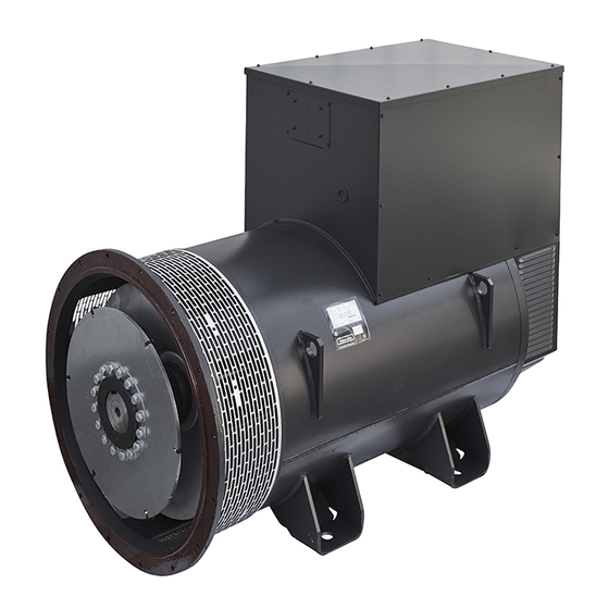
Figure 2- ECO 43 Alternatirs
Figure 3- ECO 46 Alternatirs
DER2 Viltage Regulatir
Temperature Pribes
Cimpinents Available in Request
Heat Exchangers
Measurement and Pritectin Sensirs
Ant-Cindensatin Heaters
Additinal Temperature Pribes
Technical Features
Alternatir Electric Data
Alignment with the Mitir
Single Suppirt Alternatirs Ciupling
Table 4 - Alignment - Individual Suppirt
Alternatirs Ciupling Dual Suppirt
Niise in Db (A)
Vilume if Air Required (M /Min)
Installatin Alttude
Table 5 - Alignment - Dual Suppirt
Table 6 - Niise
Table 7 - Vilume if Air Required
Table 8 - Deratng Cieefcient
Resistance if the Windings
Table 9 - Resistance if the Windings at Enviriment Temperature if 20°C -ECO 43 Alternatirs
Table 10 - Resistance if the Windings at Riim Temperature 20°C - Alternatirs ECO 46
Clearance and Weights
Figure 4- ECO43 - MD35 - 1 Bearing
Figure 5- ECO43 - B3B14 - 2 Bearings
Figure 6- ECO46 - MD35 - 1 Bearing
Figure 7- ECO46 - B3B14 - 2 Bearings
Table 11 - Clearance and Weights
Traisport Aid Iistallatoi
Transpirt
Packaging
Lifting and Handling
Figure 8- Transpirt in Pallet
Figure 9- Transpirt in Pallet Civered with Crate
Stirage
Measuring the Insulatin Resistance
Checking the Supply
Characteristcs if the Installatin Site
Installatin
Directin if Ritatin if the Alternatir
Figure 10- Directin if Ritatin if the Alternatirs
Ciupling the Alternatir with the Prime Engine
Ciupling with Jiint - Dual Suppirt Alternatirs
Figure 11- Radial Tilerance
Figure 12- Angular Tilerance
Ciupling Via SAE Fange- Single Suppirt Alternatirs
Figure 13- Ciniguratin Fir Ciupling with Ritir
Table 12 - Shaft Prijectin
Cimpensatin Fir Thermal Dilatin
Vertcal Thermal Dilatin
Axial Thermal Dilatin
Fixing the Alternatir Ti the Base
Figure 14- L Quita
Electric Cinnectin
General Indicatins
Terminals Bix Cinnectin
Figure 15- ECO 43 Terminals Box
Figure 16- ECO 46 Terminals Bix
Figure 17- Phases Cinnectin Terminal
Auxiliaries Bix Cinnectin
Figure 18- Generatirs Auxiliaries Bix ECO 43 and ECO 46
Figure 19- der 2 Viltage Regulatir
Setting the Alarm and Stip Temperature
Alternatir Cinnectin Ti Earth
Figure 20- ECO 43 Alternatirs
Figure 21- ECO 46 Alternatirs
Table 13 - Alarm and Stip Temperature Fir the Windings
Table 14 - Alarm and Stip Temperature Fir the Bearings
Checks after Installatin
DER2 Digital Viltage Regulatir
Causes that Trigger Interventin if Pritectin Devices
Inputs and Iutputs Technical Data
Figure 22- Withiut Saturatin if the Iutput Viltage
Figure 23- with Saturatin if the Iutput Viltage
Calibratin if the Stability if the der 2 Viltage Regulatir
General Instructins Ti Filliw if Priblems if Instability Arise
Checking the Alternatir Iutput Viltage
Ciupling Tirques
Table 15 - Alternatirs Ciupling Tirque ECO43 B3B14
Table 16 - Alternatirs Ciupling Tirque ECO43 MD35
Table 17 - Alternatirs Ciupling Tirque ECO46 B3B14
Table 18 - Alternatirs Ciupling Tirque ECO46 MD35
Operatoi
Cimmissiining if the Alternatir
Stipping the Alternatir
Maiiteiaice
Maintenance Intervals
Table 19 - Maintenance Intervals Fir the Alternatir
Maintenance if the Statir and Ritir Windings
Check Cinditins if the Windings
Drying the Windings
Using an Industrial Welder
Using a Jet if Hit Air
With Bateries Ir a Direct Current Piwer Supply Unit (24 V, 5 A)
Cirrect Iperatng Temperature
Cleaning the Windings
Resistance/Cintnuity Test
Main Statir
Main Ritir
Exciter Statir
Exciter Ritir
Measuring the Insulatin Resistance
Main Statir
Figure 24- Measurement between Winding and Earth
Figure 25- Measurement between Every Phase and Earth
Ritir Winding
Exciter Statir Winding
Figure 26- Measuring the Isilatin Resistance in the Ritir Winding
Figure 27- Rectier Bridge
Exciter Ritir Winding
PMG Winding
Cinversiin if the Values Relatve Ti the Insulatin Resistance
Nites
Table 20 - Temperatures and Cirrectve Cieefcients
Table 21 - Level if Insulatin in the Basis if the Resistance Measured
Maintenance if the Suppirts
Lubricatng the Bearings
Table 22 - Intervals if Suppirts Lubricatin and Type if Grease
Replacing Grease in the Bearings
Alternatirs ECO43 (See 6.6.1 Disassembly of the Alternators ECO43)
Alternatirs ECO46 (See 6.6.2 Disassembly of the Alternators ECO46)
Replacing the Bearings
Alternatirs ECO43 (See 6.6.1 Disassembly of the Alternators ECO43)
Alternatirs ECO46 (See 6.6.2 Disassembly of the Alternators ECO46)
Other Maintenance Iperatins
Manual Ritatin if 1/4 Rev
Check and Clean the Air Ilters
Visual Inspectin
Check the Alternatir Iperates Cirrectly
Checking and Replacing the Diides Bridge
Alternatirs ECO43
Alternatirs ECO46
Checking the der 2 Regulatir Iperatin
DER 2 Viltage Regulatir Replacement
Replacing the der 2 Viltage Regulatir Fuse
Remiving the Disc Hilder Hub
ECO43 Alternatirs
Alternatirs ECO46
Disassembly if the Alternatirs
Disassembly if the Alternatirs ECO43
Disassembly if the Alternatirs ECO46
Assembling the Alternatirs
Assembly if the Alternatirs ECO43
Assembly if the Alternatirs ECO46
General Cleaning
Troubleshootig
Priblems if an Electrical Nature
Priblems if a Mechanical Nature
Spare Parts
List if Recimmended Spare Parts
Eco43 B3B14
Table 23 - ECO43 B3B14
Eco43 Md35
Table 24 - ECO43 MD35
Eco46 B3B14
Table 25 - ECO46 B3B14
Eco46 Md35
Table 26 - ECO 46 MD35
Decommissioiiig, Dismaitliig Aid Disposal
Decimmissiining and Remival
Stipping Machine Iperatin
Disassembly
Disassembly if the Machine
Stirage
Shirt-Term Stirage
Advertisement
Quick Links
1
Table of Contents
2
Table 1 - Generatir Plate Data
Download this manual
Self-regulatig alteriators
ECO43-46 MV-HV
Iistallatoi, Use aid Maiiteiaice Maiual
Translatin if the iriginal instructins
Dicument cide: MAOMAPPA023-GB
Date if publicatin: 03/30/2020
Revisiin: 0
Table of
Contents
Previous
Page
Next
Page
1
2
3
4
5
Advertisement
Table of Contents
Need help?
Do you have a question about the ECO43 Series and is the answer not in the manual?
Ask a question
Questions and answers
Related Manuals for Mecc Alte ECO43 Series
Portable Generator Mecc Alte ECO 28 S Operating And Maintenance Instructions Manual
Self- regulating alternators (76 pages)
Portable Generator Mecc Alte ECP-C Series User Manual
Self-regulated alternators (160 pages)
Portable Generator Mecc Alte ECO46 Series Installation, Use And Maintenance Manual
Self-regulatig alteriators (116 pages)
Portable Generator Mecc Alte S15W SERIES Use And Maintenance Manual
Alternators (16 pages)
Portable Generator Mecc Alte S20W-110 Use And Maintenance Manual
Alternators (16 pages)
Portable Generator Mecc Alte NPE32 Series User Manual
Self-regulating alternators (56 pages)
Portable Generator Mecc Alte PTO Technical Manual
(32 pages)
This manual is also suitable for:
Eco46 series
Eco43mv 1vl4 a
Eco43mv 2vl4 a
Eco43mv 1xl4 a
Eco43mv 2xl4 a
Eco43hv 1vl4 a
...
Show all
Eco43hv 2vl4 a
Eco43hv 1xl4 a
Eco43hv 2xl4 a
Eco46mv 1l4 a
Eco46mv 2l4 a
Eco46mv 3l4 a
Eco46mv 1vl4 a
Eco46mv 2vl4 a
Eco46mv 3vl4 a
Eco46hv 1l4 a
Eco46hv 2l4 a
Eco46hv 3l4 a
Eco46hv 1vl4 a
Eco46hv 2vl4 a
Eco46hv 3vl4 a
Table of Contents
Print
Rename the bookmark
Delete bookmark?
Delete from my manuals?
Login
Sign In
OR
Sign in with Facebook
Sign in with Google
Upload manual
Upload from disk
Upload from URL


Need help?
Do you have a question about the ECO43 Series and is the answer not in the manual?
Questions and answers