
Related Manuals for National Instruments GPIB-110


Summary of Contents for National Instruments GPIB-110
- Page 1 GPIB-110 User Manual August 1994 Edition Part Number 320052-01 © Copyright 1986, 1994 National Instruments Corporation. All Rights Reserved.
- Page 2 National Instruments Corporate Headquarters 6504 Bridge Point Parkway Austin, TX 78730-5039 (512) 794-0100 Technical support fax: (800) 328-2203 (512) 794-5678 Branch Offices: Australia (03) 879 9422, Austria (0662) 435986, Belgium 02/757.00.20, Canada (Ontario) (519) 622-9310, Canada (Québec) (514) 694-8521, Denmark 45 76 26 00, Finland (90) 527 2321, France (1) 48 14 24 24, Germany 089/741 31 30, Italy 02/48301892, Japan (03) 3788-1921, Netherlands 03480-33466, Norway 32-848400, Spain (91) 640 0085, Sweden 08-730 49 70, Switzerland 056/20 51 51, U.K.
- Page 3 Limited Warranty The GPIB-110 is warranted against defects in materials and workmanship for a period of two years from the date of shipment, as evidenced by receipts or other documentation. National Instruments will, at its option, repair or replace equipment that proves to be defective during the warranty period. This warranty includes parts and labor.
- Page 4 Be sure that the equipment is plugged into a grounded outlet and that the grounding has not been defeated with a cheater plug. Notice to user: Changes or modifications not expressly approved by National Instruments could void the user’s authority to operate the equipment under the FCC Rules.
-
Page 5: Table Of Contents
Optional Equipment .......................1-4 Unpacking ........................1-4 Chapter 2 Configuration and Installation ..................2-1 Grounding Configuration....................2-1 The GPIB-110 Front and Rear Panels................2-3 The GPIB-110 Front Panel ................2-3 The GPIB-110 Rear Panel..................2-4 GPIB-110 Setup ......................2-5 Cable Selection ......................2-6 Coaxial Cable Setup...................2-6 Fiber Optic Cable Setup..................2-7 Master Switch Setting ....................2-7... - Page 6 NRFD (not ready for data) ..............C-4 NDAC (not data accepted)..............C-4 DAV (data valid)..................C-4 Interface Management Lines................C-4 ATN (attention)..................C-4 IFC (interface clear) ................C-4 REN (remote enable) ................C-4 SRQ (service request) ................C-4 EOI (end or identify)................C-4 GPIB-110 User Manual © National Instruments Corporation...
- Page 7 ........................Glossary-1 Index ..........................Index-1 Figures Figure 1-1. The Model GPIB-110 Bus Extender..............1-1 Figure 1-2. Typical GPIB-110 Extension System (Physical Configuration) ......1-2 Figure 1-3. Typical GPIB-110 Extension System (Logical Configuration)......1-2 Figure 2-1. Isolation Selection ....................2-2 Figure 2-2. Rear Panel......................2-4 Figure 2-3.
-
Page 8: About This Manual
About This Manual The GPIB-110 User Manual describes how to install, configure, and operate the GPIB-110. The GPIB-110 is a high-performance bus extender that converts IEEE 488 signals into data packets for transmission to a matching GPIB-110, using a serial communication link to the distant extender. -
Page 9: Conventions Used In This Manual
Instrumentation Customer Communication National Instruments wants to receive your comments on our products and manuals. We are interested in the applications you develop with our products, and we want to help if you have problems with them. To make it easy for you to contact us, this manual contains comment and configuration forms for you to complete. -
Page 10: Description Of The Gpib-110
• Optional rack-mount hardware The high-speed GPIB-110 Bus Extender, shown in Figure 1-1, is used in pairs with serial fiber optic or coaxial cables to connect two separate GPIB or IEEE 488 bus systems in a functionally transparent manner. While the two bus systems are physically separate, as shown in Figure 1-2, devices operate as if located on the same bus, as shown in Figure 1-3. -
Page 11: Figure 1-2. Typical Gpib-110 Extension System (Physical Configuration)
There is no speed degradation for transfers between devices on the same side of the extension. Because the GPIB-110 is a functionally transparent extender, the same GPIB communications and control programs that operate with an unextended system work unmodified with an extended system. -
Page 12: What Your Kit Should Contain
• Electrical loading limit of 15 devices per contiguous bus. Each GPIB-110 system extends the distance limit by 2 km and the loading limit to 30 devices including the extenders. You can connect these point-to-point extender systems in series for longer distances or in star patterns for additional loading. -
Page 13: Optional Equipment
Instruments for instructions. If the damage appears to have been caused in shipment, file a claim with the carrier. 3. The GPIB-110 is shipped from the factory with a 100 to 120 VAC or 220 to 240 VAC power supply. Verify that the voltage on the power supply matches the voltage that is supplied in your area. -
Page 14: Configuration And Installation
Hazardous voltage inside. Remove power cord before opening unit. Warning: 1. Turn the power switch to OFF. This switch is located on the rear panel of the GPIB-110. 2. Disconnect the power cord from the power source and from the rear panel of the GPIB-110. -
Page 15: Figure 2-1. Isolation Selection
ISO. 4. Replace the cover. Be sure the aluminum side plates are in the proper place. 5. Replace the screws you removed in Step 3. 6. Reconnect the power cord. GPIB-110 Rear Panel Top View C2 RV1 U1 U3 C5... -
Page 16: The Gpib-110 Front And Rear Panels
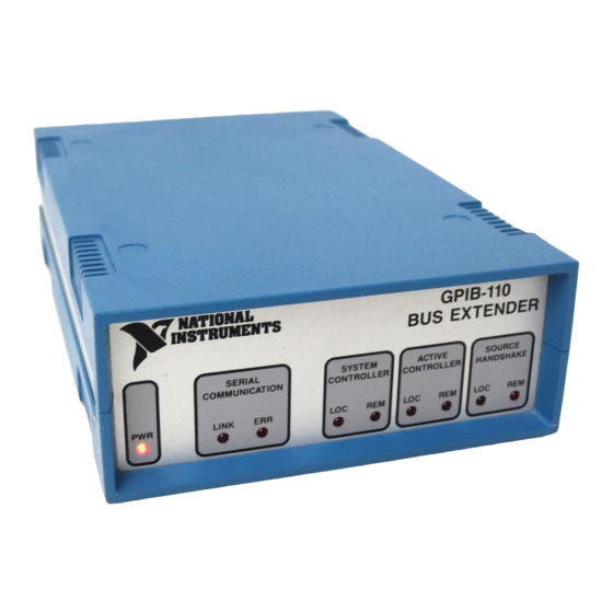
System Controller, Active Controller, and Source Handshake. The GPIB-110 Front Panel The GPIB-110 front panel is shown in Chapter 1, Figure 1-1. The front panel has nine Light Emitting Diodes (LEDs). The PWR LED on the left side of the front panel lights up whenever power is applied to the GPIB-110. -
Page 17: The Gpib-110 Rear Panel
Configuration and Installation Chapter 2 The GPIB-110 Rear Panel The GPIB-110 rear panel is shown in Figure 2-2. The rear panel contains all the GPIB-110 connectors and switches. Figure 2-2. Rear Panel The rear panel shown is for the 776103-03 (776103-33) model, which supports both fiber optic and coaxial cable. -
Page 18: Gpib-110 Setup
The main configuration switch is used to select other operating modes. This switch is located on the rear panel of the GPIB-110 and, in most cases, is the only switch you need to set before installing the GPIB-110s. Be sure to power-off the GPIB-110 before changing any switches. -
Page 19: Cable Selection
However, if you have to change the type of cable you are using, you must also change the jumper setting located on the inside of the GPIB-110 as shown in Figure 2-5. (See Figure 2-1, letter b, for the location of this jumper.) XMIT Figure 2-5. -
Page 20: Fiber Optic Cable Setup
T for transmit; the other should be marked R for receive. Connect the connector marked T to the fiber optic connector marked TRANS on the GPIB-110 rear panel. Connect the connector marked R to the fiber optic connector marked RCVR on the GPIB-110 rear panel. -
Page 21: Transmit Clock
Chapter 2 Transmit Clock The GPIB-110 has a variable transmit frequency that must be set for a given length of fiber optic or coaxial cable. If you are using fiber optic cable, set the transmit clock to 10 MHz for any length of cable. -
Page 22: Ifc Wait Mode
Respond to IDY within 200 ns with the results of the previous poll of the remote bus. Approach 2: Ignore the 200 ns rule and assume the Controller will wait sufficiently long to capture the response. Approach 3: Do not support parallel polling at all. © National Instruments Corporation GPIB-110 User Manual... -
Page 23: Latched Ppr Mode (Approach 1)
Configuration and Installation Chapter 2 The GPIB-110 supports either Approach 1 or 2 selected by Switch 7, which is located on the rear panel configuration switch as shown in Figure 2-3. Latched PPR Mode (Approach 1) This mode is selected by setting Switch 7 ON. Most Controllers pulse the IDY signal for a period of time exceeding 2 µs and expect a response within that time. -
Page 24: Installation
Verify the Voltage Requirement The GPIB-110 is shipped from the factory with either a 100 to 120 VAC or 220 to 240 VAC internal power supply. Verify that the voltage specified on the power supply matches the voltage supplied in your area. -
Page 25: Self-Test With Coaxial Cable
To run the Self-Test mode with the fiber optic cable, you must connect a single fiber optic cable in a loop from the transmit output to the receive input of the GPIB-110. You can use the opposite ends of the extension cable, or purchase a short loopback cable from National Instruments. -
Page 26: Connecting To Hewlett-Packard (Hp) Controllers
Preloading increases ringing on signal transitions and can cause improper operation of the GPIB-110. If this happens, set all signals on the Master Controller to normal (1-unit) load. This is done by using a back-panel switch. It is also important to limit the cabling to no more than 2m per device. -
Page 27: Chapter 3 Theory Of Operation
Chapter 3 Theory of Operation This chapter contains an overview of the GPIB-110 and explains the operation of each part of the GPIB-110. The GPIB-110 design consists of two main parts: • The extension circuitry • The serial communication circuitry The extension circuitry monitors the local GPIB states and converts the signals monitored into the X (for transmit) signals that are sent to the serial communication circuitry. -
Page 28: Extension Circuitry
GPIB signals are sensed and/or driven. Power On When the GPIB-110 is turned on, a reset pulse clears all circuitry to an initialized state. The units then begin executing the link establishment protocol, which is discussed in the Link Establishment Protocol section later in this chapter. -
Page 29: System Controller Detection
GPIB). The extender remains in this state until communication is established with the remote GPIB-110 unit. Once the link is established, the GPIB-110 is able to monitor the local GPIB state and receive packets containing the remote GPIB state. -
Page 30: Parallel Polling
R.RFD and R.DAC. Parallel Polling When the GPIB-110 detects ATN and EOI simultaneously asserted on the local bus, the Parallel Poll-In-Progress state becomes true and X.EOI is transmitted to the remote side along with X.ATN. -
Page 31: Data Direction Control
Parallel Poll Response byte is driven onto the GPIB DIO lines if the GPIB-110 is not in latched Parallel Poll mode. When the Parallel Poll Response is received from the remote unit, and the local EOI signal goes false, the Parallel Poll-In-Progress state becomes false. -
Page 32: Serial Communication Circuitry
When you power on, the master GPIB-110 transmits a packet to the remote unit and waits approximately 30 µs for a packet to be received. If a packet is not received, the GPIB-110 times out and retransmits the packet. This process continues until a packet is received. -
Page 33: Packet Format
GPIB-110 transmit wait time and the time it takes to transmit one packet. This equals approximately 26 µs plus the time it takes to transmit one packet, which varies depending on the transmit clock used. If a packet is not received within this time, the GPIB-110 goes into an error state. -
Page 34: System Timing And Transmission Clock
When the packet transmission has completed, the clock stops. The unit then waits for the next packet to be received. Upon power on, or when the link is not established, the clock is started in the GPIB-110 master unit to allow packet transmission to proceed. -
Page 35: Appendix A Hardware Specifications
Appendix A Hardware Specifications This appendix lists the specifications of the GPIB-110. System Configuration Distance per extension Up to 2 km Loading per extension Up to 14 additional devices Multiple extensions Permitted in any combination of star or linear pattern No restrictions (automatic conversion to 0.5 µsec... -
Page 36: Operating Characteristics
Duplex transceivers with open collector drivers for REN, SRQ, NRFD, and NDAC (MC3441). Transmission interface circuit Optically isolated coaxial drivers (75121) and receivers (75122) with BNC connectors. Optical transmitter (HFM2010-224) and receiver (HFM1011-221) with SMA-style optical cable connectors. GPIB-110 User Manual © National Instruments Corporation... -
Page 37: Environmental Characteristics
UL94V-0 flame-retardant polystyrene Dow 60875F or equivalent Rack-mounting Single or dual kits available GPIB cable National Instruments part number 763061-xx or equivalent Belden V.P.C. part number 95680 75 Ω coaxial Transmission cable cable 9248, RG-6/U type with male BNC connectors. -
Page 38: Multiline Interface Messages
The multiline interface messages are IEEE 488-defined commands that are sent and received with ATN TRUE. For more information on these messages, refer to the ANSI/IEEE Standard 488-1987, IEEE Standard Digital Interface for Programmable Instrumentation. © National Instruments Corporation GPIB-110 User Manual... - Page 39 MLA27 < MLA28 MLA29 > MLA30 Message Definitions Device Clear My Secondary Address Group Execute Trigger My Talk Address Go To Local Parallel Poll Configure Local Lockout Parallel Poll Disable My Listen Address GPIB-110 User Manual © National Instruments Corporation...
- Page 40 MTA24 MSA24,PPD MTA25 MSA25,PPD MTA26 MSA26,PPD MTA27 MSA27,PPD MTA28 MSA28,PPD MTA29 MSA29,PPD MTA30 MSA30,PPD Parallel Poll Enable Serial Poll Enable Parallel Poll Unconfigure Take Control Selected Device Clear Unlisten Serial Poll Disable Untalk © National Instruments Corporation GPIB-110 User Manual...
- Page 41 T, TE [MTA] my talk address other secondary address other talk address T, TE primary command group TE, LE, PP parallel poll configure [PPD] parallel poll disable [PPE] parallel poll enable GPIB-110 User Manual © National Instruments Corporation...
- Page 42 (via C) remote enable ready for data request service T, TE [SDC] selected device clear (via C) serial poll disable (via C) serial poll enable (via C) service request © National Instruments Corporation GPIB-110 User Manual...
- Page 43 Multiline Interface Messages Appendix B Interface Message Reference List (Continued) Remote Messages Sent (Continued) Mnemonic Message Interface Function(s) status byte (via T, TE) take control (via C) unlisten (via C) untalk (via C) GPIB-110 User Manual © National Instruments Corporation...
-
Page 44: Appendix C Operation Of The Gpib
The GPIB is a bus like a typical computer bus except that the computer has its circuit cards interconnected via a backplane bus whereas the GPIB has stand-alone devices interconnected via a cable bus. © National Instruments Corporation GPIB-110 User Manual... -
Page 45: Controller-In-Charge And System Controller
The interface bus consists of 16 signal lines and 8 ground return or shield drain lines. The 16 signal lines are divided into three groups: • Eight data lines • Three handshake lines • Five interface management lines GPIB-110 User Manual © National Instruments Corporation... -
Page 46: Data Lines
Three lines asynchronously control the transfer of message bytes among devices. The process is called a three-wire interlocked handshake and it guarantees that message bytes on the data lines are sent and received without transmission error. © National Instruments Corporation GPIB-110 User Manual... -
Page 47: Nrfd (Not Ready For Data
The EOI line has two purposes. The Talker uses it to mark the end of a message string. The CIC uses it to tell devices to identify their responses in a parallel poll. GPIB-110 User Manual © National Instruments Corporation... -
Page 48: Physical And Electrical Characteristics
See Figures C-2 and C-3. GPIB Cables Device A Device B Device C Figure C-2. Linear Configuration of the GPIB Devices © National Instruments Corporation GPIB-110 User Manual... - Page 49 The GPIB uses negative logic with standard transistor-transistor logic (TTL) levels. For example, when DAV is true, it is a TTL low level (≤ 0.8 V), and when DAV is false, it is a TTL high level (≥ 2.0 V). GPIB-110 User Manual © National Instruments Corporation...
-
Page 50: Configuration Restrictions: The Role Of Extenders And Expanders
Expanders or repeaters generally buffer one bus from an adjacent bus that doubles the total cable and loading limits. The GPIB-110 is a serial extender that uses either low-cost coaxial cable or high-performance electrically isolated fiber-optic cable as its transmission medium. The GPIB-110 samples GPIB signals on each bus to which it is connected, serializes the information encoded in small packets, and transmits the packets to the remote side. -
Page 51: Customer Communication
Filling out a copy of the Technical Support Form before contacting National Instruments helps us help you better and faster. National Instruments provides comprehensive technical assistance around the world. In the U.S. and Canada, applications engineers are available Monday through Friday from 8:00 a.m. to 6:00 p.m. - Page 52 National Instruments for technical support helps our applications engineers answer your questions more efficiently. If you are using any National Instruments hardware or software products related to this problem, include the configuration forms from their user manuals. Include additional pages if necessary.
- Page 53 GPIB-110 Hardware and Software Configuration Form Record the settings and revisions of your hardware and software on the line to the right of each item. Update this form each time you revise your software or hardware configuration, and use this form as a reference for your current configuration.
- Page 54 Documentation Comment Form National Instruments encourages you to comment on the documentation supplied with our products. This information helps us provide quality products to meet your needs. Title: GPIB-110 User Manual Edition Date: August 1994 Part Number: 320052-01 Please comment on the completeness, clarity, and organization of the manual.
-
Page 55: Glossary
Federal Communications Commission fiber optic GPIB General Purpose Interface Bus Hewlett-Packard hertz Identify message Interface Clear inches International Standards Organization kbytes 1,000 bytes Local Active Controller light-emitting diode Local LED Local Source state © National Instruments Corporation Glossary-1 GPIB-110 User Manual... - Page 56 Mbytes 1,000,000 bytes numerical aperture Parallel Poll Response Polyvinylchloride Remote Active Controller Remote LED Remote Source state Remote System Controller seconds transistor-transistor logic volts volts alternating current watts GPIB-110 User Manual Glossary-2 © National Instruments Corporation...
-
Page 57: Index
3-3 IFC Wait Mode, 2-9 ATN line (attention), C-4 Immediate Extension Mode, 2-8 master switch setting, 2-7 RCVR connector, 2-4 on rear panel of GPIB-110, 2-4 TRANS connector, 2-4 cables Controllers coaxial cable setup, 2-6 Controller-in-Charge, C-2... - Page 58 ATN (attention), C-4 EOI (end or identify), C-4 IFC (interface clear), C-4 REN (remote enable), C-4 GPIB-110 bus extender. See also operation SRQ (service request), C-4 of the GPIB; theory of operation. block diagram, 3-2 contents of kit, 1-3...
- Page 59 C-6 to C-7 GPIB signals data lines, C-3 GPIB cable connector (illustration), RCVR connector, 2-4 rear panel of GPIB-110, 2-4 handshake lines, C-3 to C-4 Receive Packet state, 3-7 interface management lines, C-4 Receive Wait state, 3-7 overview, C-2...
- Page 60 Receive Packet state, 3-7 the GPIB. Receive Wait state, 3-7 Active Controller detection, 3-3 Transmit Packet state, 3-7 block diagram of GPIB-110, 3-2 transmit synchronization state, 3-7 data direction control, 3-5 system timing and transmission clock, EOI, 3-5 overview, 3-1...
Need help?
Do you have a question about the GPIB-110 and is the answer not in the manual?
Questions and answers