Table of Contents
Advertisement
Quick Links
Advertisement
Table of Contents

Related Manuals for Nordmann Engineering Omega Pro


Summary of Contents for Nordmann Engineering Omega Pro
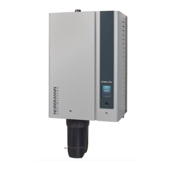
- Page 1 Nordmann Omega Pro Steam humidifier OPERATION MANUAL 2588792-A EN 1807...
- Page 2 Nordmann Engineering AG, except to the extent required for installation or maintenance of recipient's equipment. Liability Notice Nordmann Engineering AG does not accept any liability due to incorrect installation or operation of the equipment or due to the use of parts/components/equipment that are not authorised by Nordmann Engineering AG. Copyright Notice ©...
-
Page 3: Table Of Contents
Product Overview Construction Nordmann Omega Pro steam humidifier Functional description System overview Nordmann Omega Pro for duct humidification System overview Nordmann Omega Pro for direct room humidification Operation First-time commissioning Display and operating elements Commissioning after an interruption of operation Notes on operation 4.4.1... - Page 4 Important notes on maintenance Maintenance intervals Maintenance list Removing and installing components for maintenance 6.4.1 Preparing the Nordmann Omega Pro for the removal of components 6.4.2 Removal and installation of the scale collector tank 6.4.3 Removal and installation of the steam cylinder 6.4.4...
-
Page 5: Introduction
To the very beginning We thank you for having purchased the Nordmann Omega Pro steam humidifier. The Nordmann Omega Pro steam humidifier incorporates the latest technical ad van ces and meets all recognized safety standards. Nevertheless, improper use of the Nordmann Omega Pro steam humidifier may result in danger to the user or third parties and/or damage to property. - Page 6 Symbols used in this manual CAUTION! The catchword "CAUTION" used in conjunction with the caution symbol in the circle designates notes in this operation manual that, if neglected, may cause damage and/or malfunction of the unit or damage to property. WARNING! The catchword "WARNING"...
-
Page 7: For Your Safety
For safety and warranty reasons any action beyond the scope of this manual must be carried out only by qualified personnel authorised by Nordmann. It is assumed that all persons working with the Nordmann Omega Pro are familiar and comply with the appropriate regulations on work safety and the prevention of accidents. - Page 8 Nordmann Omega Pro is no longer operating correctly – if connections and/or piping are not sealed All persons working with the Nordmann Omega Pro must report any alterations to the unit that may af- fect safety to the owner without delay. Prohibited modifications to the unit No modifications must be undertaken on the Nordmann Omega Pro without the express written consent of Nordmann.
-
Page 9: Product Overview
29 Ground terminals 14 Condensate connector (to drain) 30 Main contactor 15 Steam connector (ø45 mm) 31 Heating contactors 16 Steam outlet hose 32 Power board Fig. 1: Construction Nordmann Omega Pro steam humidifier (figure shows medium sized unit) Product Overview... -
Page 10: Functional Description
Functional description The Nordmann Omega Pro steam humidifier is an atmospheric steam generator. It operates on the resistance heating principle and is designed for direct room air humidification (with blower pack) and indirect humidification (with steam distributor) in venti lating and air-conditioning systems. -
Page 11: System Overview Nordmann Omega Pro For Duct Humidification
7 Filter valve (accessory Z261) 16 Humidity controller or humidity sensor 8 Open funnel with water trap 17 Humidity controller or humidity sensor 9 Drain hose (supplied) 18 High limit humidistat Fig. 2: System overview Nordmann Omega Pro for duct humidification Product Overview... -
Page 12: System Overview Nordmann Omega Pro For Direct Room Humidification
6 Manometer (recommended) 14 Blower Pack (accessory BP) 7 Filter valve (accessory Z261) 15 Humidity controller or humidity sensor Open funnel with water trap 16 High limit humidistat Fig. 3: System overview Nordmann Omega Pro for direct room humidification Product Overview... -
Page 13: Operation
Operation The Nordmann Omega Pro steam humidifier may be commissioned and operated only by persons familiar with the Nordmann Omega Pro steam humidifier and adequately qualified. It is the owner’s responsibility to verify proper qualification of the personnel. First-time commissioning The first-time commissioning must always be done by a service technician of your Nordmann repre- sentative or a well trained and authorised person of the customer. -
Page 14: Commissioning After An Interruption Of Operation
5.1.2). If the function check on the level unit is successful, the Nordmann Omega Pro will be in normal operating mode and the standard operating display is shown. The heating current switches on as soon as the humidity controller/humidistat demands humidity. The LED lights green and steam is produced after a short delay. -
Page 15: Notes On Operation
Notes on operation 4.4.1 Inspections during operation During operation the Nordmann Omega Pro and the humidification system have to be inspected weekly. On this occasion check the following: • the water and steam installation for any leakage. • the steam humidifier and the other system components for correct fixing and any damage. -
Page 16: Draining Of The Steam Cylinder
The drain cycle is stopped and the unit returns to the "Manual" submenu. 4. If you have to carry out work on the Nordmann Omega Pro, switch off steam humidifier via the unit switch. Otherwise the steam cylinder is immediately filled again. -
Page 17: Taking The Unit Out Of Operation
Taking the unit out of operation In order to take the Nordmann Omega Pro steam humidifier out of operation (e.g. for maintenance pur- pose), perform the following steps: 1. Close the shut-off valve in the water supply line. 2. If you have to carry out maintenance work on the steam cylinder and/or on the scale collector tank... -
Page 18: Operating The Control Software
Operating the control software Standard operating display After switching on the Nordmann Omega Pro and the automatic system test the steam humidifier is in normal operating mode and the standard operating display is shown. Note: the appearance of the standard operating display depends on the current operating status and the configuration of the humidity control of the system and can deviate from the display shown below. -
Page 19: Operating Status Indication
Carry out the small maintenance, then reset the maintenance counter in the "Service" submenu. A malfunction with status "Warning" is active. Additionally the status LED lights yellow. Depend- ing on the malfunction the Nordmann Omega Pro is either be stopped or stays operable for a certain period of time. -
Page 20: Navigating/Operating The Control Software
Navigating/Operating the control software Navigation element Action Accessing main menu Accessing system informations Performing manual steam cylinder draining Accessing help screen If you press on a field with a blue arrow symbol a new screen with additional informations or settings appears. This symbol on the left side of the operating status field and of the mainte- nance/malfunctions indication field indicates, that the system is working ok. -
Page 21: Information Functions
Information functions 5.3.1 Accessing support informations In the standard operating display press the <Help> button. The screen with the support information appears. 5.3.2 Accessing system informations In the standard operating display press the <About> button. The system information screen appears. Use the arrow buttons to scroll up and down within the system information screens to access the different system information and operating data. - Page 22 Serial Number: Serial number of the steam humidifier. – Graph: With this function you can access the graphical display of the performance diagram of the Nordmann Omega Pro. – Export Trend Data: With this function you can save the data of the per- formance diagram as .csv file to a USB memory stick (FAT32 formatted).
- Page 23 BACnet communication protocol is disabled. Online Status: shows the connection status of the Nordmann Omega – Pro to Nordmann Online("Connected" or "Disconnect'd"). – IP Address: shows the IP address of the Nordmann Omega Pro. Operating the control software...
- Page 24 Parameters Tab on page 41 for more details. Online Status: shows the connection status of the Nordmann Omega – Pro to Nordmann Online ("Connected" or "Disconnect'd"). – IP Address: shows the IP address of the Nordmann Omega Pro. Operating the control software...
-
Page 25: Configuration
Password: 3562 5.4.2 Activating/deactivating and configuration of options – "Features" submenu In the "Features" submenu you can determine different operating parameters of the Nordmann Omega Pro. Water Management Tab – Water Mode: with this setting you determine whether the flushing interval... - Page 26 – Maintenance Small: with this setting you determine the interval time in hours for the small maintenance. Factory setting: dependent on the steam capacity Setting range: 100 ... 3'000 h – Maintenance Extended: with this setting you determine the interval time in hours for the extended maintenance.
- Page 27 Idle Mode Tab – Idle Mode: with this setting you determine the operational behaviour of the Nordmann Omega Pro in standby operation. Factory setting: Idle Drain Options: Idle Drain (the steam cylinder is drained and re- filled after a set time in standby operation)
- Page 28 The following settings appear only, if "Idle Mode" is set to "Keep Warm". Note: If the keep warm function for standby operation is activated the temperature of the water in the steam cylinder is held on 60 °C (at 20 °C ambient temperature), so that the humidifier can produce steam as fast as possible as soon as a demand is present again.
- Page 29 Manual Capacity A: with this button you can access the settings menu for the capacity limitation. Here you determine whether the Nordmann Omega Pro is to be operated with a fix capacity limitation (factory setting) or whether it is to be operated with a timer controlled capacity limitation.
- Page 30 – Operation with timer controlled capacity limitation Activate the timer function (Capacity Timers: "On"). If the capacity timer is activated, up to eight switching points (Event 1... Event 8) with different capacity limits can be defined. Each switching point is defined by a weekday or weekday range, the switching time and the capacity limitation in % of the maximum capacity.
- Page 31 ("Off") the optional drain valve for the automatic draining of the scale col- lector tank in standby operation. Note: if the optional drain valve is activated, the Nordmann Omega Pro is completely drained in standby operation (including scale collector tank) and refilled only after a humidity demand is present again.
- Page 32 Accessory Board Tab Note: the "Accessory Board" tap with the corresponding settings appears only, if the optional accessory board (for the control of an external fan of the ventilation system or the optional valve for flushing the water supply line) is installed and activated in the factory level. –...
-
Page 33: Humidity Control Settings - "Control Settings" Submenu
5.4.3 Humidity control Settings – "Control Settings" submenu In the "Control Settings" submenu you determine the control settings for the Nordmann Omega Pro steam humidifier. The control settings available depend on the selected signal source and the control mode as well as whether the steam humidifier is controlled with supply air limitation. - Page 34 Setpoint Channel 1: with this button you can access the settings menu for the humidity setpoint. Here you determine whether the Nordmann Omega Pro is to be controlled with a fix humidity setpoint (factory set- ting) or whether it is to be operated timer controlled with different humidity setpoints.
- Page 35 – Operation with timer controlled capacity limitation Activate the timer function (Setpoint Timers: "On"). If the setpoint timer is activated, up to eight switching points (Event 1... Event 8) with different humidity setpoints can be defined. Each switching point is defined by a weekday or weekday range, the switching time and the humidity setpoint in %rh.
- Page 36 Factory setting: Setting range: 1 ... 10 % – Enable Input: With this setting you determine wether the Nordmann Omega Pro can be enabled and disabled via an external enable contact ("On") or not ("Off"). Factory setting: Options: On or Off...
-
Page 37: Basic Settings - "General" Submenu
5.4.4 Basic settings – "General" submenu In the "General" submenu you determine the basic settings for operating the Nordmann Omega Pro control software. Basic Tab Date: with this setting you determine the current date in the set format – ("MM/DD/YYYY" or "DD/MM/YYYY", see Time/Date Tab below). -
Page 38: Communication Settings - "Communication" Submenu
Fixed (fixed assignment) – IP Address: with this setting you manually enter the IP Address of the Nordmann Omega Pro. Note: This IP Address is used if "IP Type" is set (or reverts) to "Fixed". – Subnet Mask: with this setting you determine the Subnet Mask of the IP network. - Page 39 MAC Address: factory set MAC Address (Media Access Control) of the Nordmann Omega Pro. Not modifiable. – Host Name: Host Name of the Nordmann Omega Pro automatically gen- erated by the control. Format: "IC_"+"Serial number of the device". Not modifiable.
- Page 40 Off or On The following parameters appear only if the Modbus function is activated. – Modbus Address: with this setting you determine the Modbus address for the Nordmann Omega Pro for the communication via a Modbus network. Factory setting: Setting range: 1 ...
- Page 41 The following settings appear only, if the parameter "BACnet" is set to "BACnet/IP". – Device Name: with this setting you determine the name of the Nord- mann Omega Pro for the communication via the integrated BACnet interface. – Device Description: with this setting you determine a short descrip- tion of the Nordmann Omega Pro.
- Page 42 The following settings appear only, if the parameter "BACnet" is set to "MSTP". Note: with BACnet MSTP the Nordmann Omega Pro acts as a slave node only device. – Parity: with this setting you set the parity bit for the data transfer.
-
Page 43: Maintenance Functions
Maintenance functions 5.5.1 Accessing the "Service" submenu Password: 3562 5.5.2 Performing maintenance functions – "Service" submenu In the "Service" submenu you can reset the maintenance counters, access and save the fault and main- tenance history and perform different diagnostic functions. General Service Tab –... - Page 44 Fault/Service History Tab Note: the fault and maintenance events stored can be correctly analysed only if the data and the time of day are correctly set. – Fault History: with this function you can access the fault history list where the last 40 fault events are stored.
- Page 45 5.5.2.1 Input diagnostic functions – "Input Diagnostics" submenu The following input values can be viewed after accessing the "Input Diagnostics" submenu. Note: the input values can be accessed and viewed too, via the "Service Info" selection field in the standard operating display. Cylinder A Tab (Cylinder B Tab) Note: the tabs of the input diagnostics for Cylinder B appear only on double units.
- Page 46 – 24V External Supply: Actual voltage of the external 24 V supply. – 10V External Supply: Actual voltage of the external 10 V supply. 5.5.2.2 Relay diagnostic functions – "Relay Diagnostics" submenu Remote Fault board Tab – Running: with this function you can activate ("On") and deactivate ("Off") the relay "Steam"...
-
Page 47: Administration Settings
Administration settings 5.6.1 Accessing "Administrator" submenu Password: 3562 5.6.2 Switching on/off password protection and software updates function - submenu "Administrator" In the "Administrator" submenu you can activate and deactivate the password protection for the main menu and the setpoint, and download software updates via a USB stick connected to the USB connector. Password settings Tab –... - Page 48 Software Settings Tab – Software Update: with the function "Software Update" you can update the control software of the integrated controller. See information in chapter 6.8. – Driver A.DB.A Update: with the function "Ext.A.DB.A Update" you can update the driver board software of steam humidifier A.See information chapter 6.8.
-
Page 49: Maintenance
Prevention: Before carrying out any work on the steam system set the Nordmann Omega Pro out of operation as described in chapter 4.5, then wait until the components have cooled down sufficiently... -
Page 50: Maintenance Intervals
Maintenance intervals To maintain operational safety the Nordmann Omega Pro steam humidifier must be maintained at regu- lar intervals. The control software of the Nordmann Omega Pro features two maintenance counters one for the "Small maintenance" (Cleaning of the scale collector tank, only for units equipped with a scale collector tank) and one for the "Extended maintenance"... -
Page 51: Maintenance List
Maintenance list Adjacent you can find an overview of the maintenance work to be carried out on "Small maintenance" and "Extended maintenance". Components Work to be done Scale collector tank Remove and clean. Note: the scale collector tank must be replaced at the latest after 5.000 operation hours or after 3 years. -
Page 52: Removing And Installing Components For Maintenance
6.4.1 Preparing the Nordmann Omega Pro for the removal of components Before starting any removal work set the Nordmann Omega Pro out of operation and drain the steam cylinder and the scale collector tank (if applicable). Proceed as follows: 1. Nordmann Omega Pro must be switched on. Perform a draining of the steam cylinder (see chapter 4.4.3). -
Page 53: Removal And Installation Of The Scale Collector Tank
6.4.2 Removal and installation of the scale collector tank Removal WARNING! Danger of burning! Before removal of the scale collector tank ensure it is empty and the temperature indication adhesive on the scale collector tank indicates a temperature <122 °F (<50°C). Snap ring O-ring Strainer... - Page 54 Installation Prior to the installation: • Check scale collector tank, O-ring, snap ring and strainer insert for damages and replace defective components if necessary. We recommend to replace the sealings of the scale collector tank with each maintenance. For that purpose a maintenance kit is available (see parts list). •...
-
Page 55: Removal And Installation Of The Steam Cylinder
6.4.3 Removal and installation of the steam cylinder WARNING! Danger of burning! Before removal of the steam cylinder ensure the steam cylinder is empty and has cooled down, that no more burning danger exists. 1. Loosen retaining screw on front door on the steam cylinder side of the unit using a screwdriver, then remove the front door. - Page 56 3. Carefully lift the steam cylinder out of steam cylinder receptacle and remove it towards the front of the unit. CAUTION! Set down the steam cylinder carefully to ensure the funnel on the bottom side of the cylinder is not damaged! 4.
- Page 57 6. If necessary, loosen the funnel insert by lightly rotating it in either direction and lift it together with baffle from the steam cylinder. Then, remove the screen insert from the funnel insert. 7. If during maintenance one or more heating elements must be replaced: •...
-
Page 58: Removal And Installation Of The Drain Cup
Assembly and installation of the steam cylinder Assembly of the steam cylinder takes place in reverse sequence of the removal. Please note the fol- lowing instructions: – Installation of any heating elements which have been removed should follow the figure of step 7. Please take care that the heating elements are correctly positioned and the cables are correctly connected (according to your notes). -
Page 59: Removal And Installation Of The Filling Cup, The Level Unit And The Water Hoses
6.4.5 Removal and installation of the filling cup, the level unit and the water hoses For removing the filling cup, the level unit and the water hoses the steam cylinder must be removed first (see chapter 6.4.3). 1. Release hose clamps, then disconnect all hoses from the corresponding connectors and remove the hoses. -
Page 60: Removal And Installation Of The Drain Pump
6.4.6 Removal and installation of the drain pump For removing the drain pump the steam cylinder must be removed first (see chapter 6.4.3). 1. Detach electric cables (polarity of the cables must not be observed). 2. Release hose clamps and remove the hoses from the connectors. 3. -
Page 61: Removal And Installation Of The Inlet Valve
6.4.7 Removal and installation of the inlet valve For removing the inlet valve the steam cylinder must be removed first (see chapter 6.4.3). 1. Detach electric cables (polarity of the cables must not be observed). Important: on multiple valves (units with increased control accuracy or units with option drain cooling) ensure to reconnect the connecting cables to same valve (note position). -
Page 62: Removal And Installation Of The Steam Cylinder Receptacle
6.4.8 Removal and installation of the steam cylinder receptacle For removing the steam cylinder receptacle the steam cylinder must be removed first (see chapter 6.4.3). 1. Release hose clamps and remove hoses from the connectors. 2. Undo the screw fixing cylinder receptacle to the bottom of the housing with Phillips screwdriver. 3. -
Page 63: Notes On Cleaning The Unit Components
Notes on cleaning the unit components Unit component What to clean and how to clean Scale collector tank • Dump any lime in scale collector tank, then carefully knock off any limescale inside scale collector tank and on the strainer insert. If the scale collector tank heavily calcified, fill scale collec- tor tank with an 8% formic acid solution (observe safety notes in... - Page 64 Unit component What to clean and how to clean Hoses • Remove any limescale by slightly knocking on the tubes using a rubber hammer. Then, rinse the tubes well with hot tap water. Inlet valve • Use a soft bristled brush (do not use a wire brush) to remove any limescale inside the inlet valve and on the strainer.
-
Page 65: Notes On Cleaning Agents
Unit component What to clean and how to clean Drain cup • Use a soft bristled brush (do not use a wire brush) to remove any limescale from the drain cup and its con- nectors. If the drain cup is heavily calcified, place it in an 8% formic acid solution (observe safety notes in chapter 6.6), until the limescale comes off. -
Page 66: Resetting The Maintenance Counter
Resetting the maintenance counter After completing the "Small maintenance" or the "Extended maintenance", the corresponding mainte- nance indication or maintenance counter (for module A or module B or for both), respectively must be reset. Proceed as follows to reset the maintenance counter: 1. -
Page 67: Performing Software And Firmware Updates
Performing software and firmware updates To update the control software or the driver board firmware, proceed as follows: 1. Set the On/Off switch on the front side of the steam humidifier to the Off position, then switch off the voltage supply to the steam humidifier via the external disconnect switch (electrical isolator) and secure switch in the off position to prevent it from inadvertent power up. -
Page 68: Fault Elimination
General notes Only use original spare parts from your Nordmann representative to replace defective parts. Safety Before starting repair work on the Nordmann Omega Pro set the unit out of operation and disconnect it from the mains (see chapter 4.5). -
Page 69: Fault Indication
Fault indication Malfunctions during operation detected by the control software are indicated by a corresponding Warning message (operation still possible) or Fault message (operation not longer possible) in the maintenance and fault indication field in the standard display of the control unit. Warning Temporary problems (e.g. -
Page 70: Malfunction List
––– Max. Filling Time The Nordmann Omega Pro is monitoring the filling process with different levels which have to be reached within a preset time during filling. If a certain level is not reached within the preset time the fault message "Max. Filling Time"... - Page 71 Max. Drain Time The level in the steam cylinder has not dropped to the preset level within the preset time. The Nordmann Omega Pro carries out a level test. This procedure is repeated three times if maximum drain time is exceeded again,...
- Page 72 Code Message Information Warning Fault Possible causes Remedy ––– E74 ** Keep Alive Communication between control board and driver board interrupted. Driver board not connected. Correctly connect driver board. Wrong driver board installed. Install and connect correct driver board. Driver board defective. Replace driver board.
- Page 73 Jumper wire "J1" not connected to Connect jumper wire "J1" to terminal terminal block "X12" on driver board. block "X12" on driver board. These fault messages must be reset by switching the Nordmann Omega Pro off and on again (see chapter 7.5) Fault elimination...
-
Page 74: Saving Fault And Service Histories To A Usb Memory Stick
Saving fault and service histories to a USB memory stick The fault and service histories of the Nordmann Omega Pro can be saved to a USB memory stick for logging and further analysis. For this purpose proceed as follows: 1. Set the On/Off switch on the front side of the steam humidifier to the Off position, then switch off the voltage supply to the steam humidifier via the external disconnect switch (electrical isolator) and secure switch in the off position to prevent it from inadvertent power up. -
Page 75: Replacing The Fuses And Backup Battery In The Control Unit
Fig. 6: Position of the backup battery and the fuses on the driver board 5. Swivel control board assembly 90°inwards. 6. Relocate front cover on control unit and lock it with the retaining screw. 7. Reconnect Nordmann Omega Pro to the mains by switching on the electrical isolator. Fault elimination... -
Page 76: Taking Out Of Service/Disposal
Taking out of service/Disposal Taking out of service If the Nordmann Omega Pro must be replaced or if the Nordmann Omega Pro is not needed any more, proceed as follows: 1. Take the Nordmann Omega Pro out of operation as described in chapter 4.5. -
Page 77: Product Specification
Product specification Performance data 230V/1~/50...60 Hz 200V/3~/50...60 Hz 230V/3~/50...60 Hz 380V/3~/50...60 Hz 400V/3~/50...60 Hz 415V/3~/50...60 Hz Omega 16.5 –– –– –– –– –– 26.0 –– –– –– –– –– 15.0 32.0 10.0 –– –– –– –– –– 18.5 10.2 10.0 11.0 10.7 11.5... -
Page 78: Operating Data
Operating data Control accuracy ±5 % absolute humidity (with PI-control and use of untreated drinking water) ±2 % absolute humidity (with PI-control and use of de-ionized water) Control steam output – active 0…5 VDC, 1…5 VDC, 0…10 VDC, 2…10 VDC, 0…20 VDC, 0…16 VDC, 3.2…16 VDC, 0…20 mADC, 4…20 mADC –... - Page 80 CH94/0002.01 Nordmann Engineering AG Lindenhofstrasse 28, 4052 Basel, Switzerland Phone +41 61 404 46 50, Fax +41 61 404 46 79 www.nordmann-engineering.com info@nordmann-engineering.com...
Need help?
Do you have a question about the Omega Pro and is the answer not in the manual?
Questions and answers