Table of Contents
Advertisement
Quick Links
Advertisement
Table of Contents
Troubleshooting

Related Manuals for MOGlabs MOA


Summary of Contents for MOGlabs MOA
- Page 1 Amplified laser system Model MOA/MSA Revision 1.09...
- Page 2 MOGL Contact For further information, please contact: MOG Laboratories P/L MOGLabs USA LLC 49 University St 419 14th St Carlton VIC 3053 Huntingdon PA 16652 AUSTRALIA +61 3 9939 0677 +1 814 251 4363 info@moglabs.com...
- Page 3 We hope that the works well for your application, and please let us know if you have any suggestions for improvement of the or this document, so that we can make life in the lab better for all. abs, Melbourne, Australia MOGL www.moglabs.com...
-
Page 5: Safety Precautions
Safety Precautions Your safety and the safety of your colleagues depends on careful attention to proper operation of this product. Please read the following safety in- formation before attempting to operate. Also please note several specific and unusual cautionary notes before using the MOGL in addition to the safety precautions that are standard for any electronic equipment. - Page 6 • Note the safety labels (examples shown in figure below) and heed their warnings. • The must be operated with a controller with keyswitch interlock. The must not be powered unless the keyswitch is inserted and switched on. It should not be possible to remove the keyswitch without turning off...
- Page 7 Label identification The International Electrotechnical Commission laser safety standard IEC 60825-1:2007 mandates warning labels that provide information on the wavelength and power of emitted laser radiation, and which show the aperture where laser radiation is emitted. Figures 1 and 2 show examples of these labels and their location on the Model number: MSA003...
- Page 8 FDA compliance and serial number Emission indicators Model number: MSA003 Serial number: A41706002 Manufactured: JUNE 2017 VISIBLE LASER RADIATION Complies with 21 CFR 1040.10, and 1040.11 except for AVOID EYE OR SKIN EXPOSURE TO deviations pursuant to Laser Notice No.50, dated 24 June 2007 DIRECT OR SCATTERED RADIATION MOG Laboratories Pty Ltd, 49 University St CLASS 4 LASER PRODUCT...
-
Page 9: Table Of Contents
3.4 Measure PI curve ......4 MOA: external seed alignment 4.1 Seed alignment ...... - Page 10 B Electrical connections B.1 MOA amplifier headboard ....B.2 Connector pinouts ......
-
Page 11: Introduction
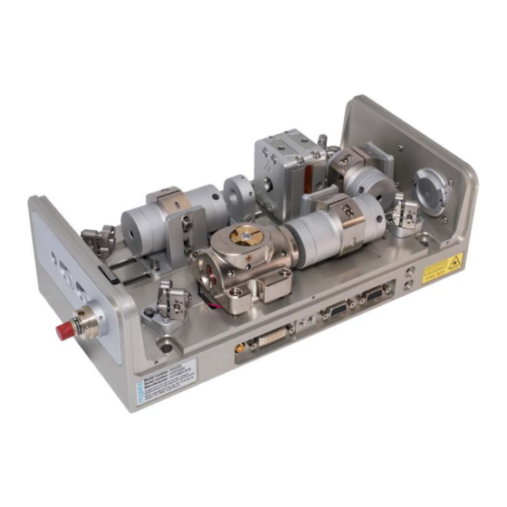
1. Introduction is a semiconductor laser amplifier with injection seed MOGL laser. The is an amplifier-only configuration of the , without seed laser. The amplifier block (see figure 1.1) consists of the core semicon- ductor tapered amplifier diode and aspheric input and output collimation lenses in flexure translation stages. - Page 12 Chapter 1. Introduction The tapered amplifier diode is user-replaceable (see chapter 7). Two flex- ure stages control the transverse position of the input and output collima- tion lenses, providing precise alignment with mechanical stability. Finely threaded tubes control the focus of the lenses. In normal operation, the seed laser produces a collimated beam with power of 10 to 30 mW.
-
Page 13: First Light
2. First light 2.1 Basic setup Initial installation of the device is typically a matter of mounting it to an optical table and connecting to controllers. Mount- MOGL ing holes can be accessed by removing the cover, and M6 x 16 socket head cap screws can then fix the device to the optical table. -
Page 14: Polarisation Control
Chapter 2. First light 2.2 Polarisation control The polarisation of the seed and output beams can be controlled with half- wave retarders. The seed polarisation must match the diode and con- trol of the output polarisation can be useful for matching to polarisation- maintaining ( ) singlemode fibre (see chapter 6). -
Page 15: First Light
2.3 First light 2.3 First light WARNING Do not operate the amplifier above the maximum unseeded current speci- fication without input seed. The input seed power must be at least 10 mW, and properly mode-matched to the tapered amplifier diode. Operation without appropriate seed will destroy the tapered amplifier diode. - Page 16 Chapter 2. First light can be checked using a sheet polariser (for example, a linear po- larising filter from a photographic store). The beams should have similar cross-sections. If there is any concern that the system alignment has been disturbed in shipping, please contact abs before proceeding to full seed MOGL...
-
Page 17: Msa: Internal Seed Alignment
3. MSA: internal seed alignment WARNING Do not operate the amplifier above the maximum unseeded current speci- fication without input seed. The input seed power must be at least 10 mW, and properly mode-matched to the tapered amplifier diode. Operation without appropriate seed will destroy the tapered amplifier diode. -
Page 18: Seed Alignment
Chapter 3. MSA: internal seed alignment have been inserted into the final isolator if needed (see your test report). Please contact abs if further information is required. MOGL 3.3 Seed alignment If the tapered amplifier ( ) diode is operated without injection seed, all of the electrical input energy is lost as heat, and at high current there is significant risk of damaging the diode. - Page 19 3.3 Seed alignment be detected exiting from the input side of the diode. Do not exceed the maximum unseeded current specified in the test data for your device (300 to 700 mA). It may be necessary to use a video camera (e.g.
- Page 20 Chapter 3. MSA: internal seed alignment 7. Install the first isolator and optimise transmission to the . The polarisation will not match the diode, and therefore a waveplate rotator will be required between the isolator and . Typically the second isolator will have a waveplate mounted inside the exit aper- ture (see fig.
- Page 21 3.3 Seed alignment (f) Once horizontal alignment is optimized, repeat steps (c) through (e) for the vertical alignment. (g) Iterate the horizontal and vertical alignment procedure until you can no longer increase the output power. You may need to drop the output power by less than 25% as your alignment improves, e.g.
-
Page 22: Measure Pi Curve
Chapter 3. MSA: internal seed alignment 13. Verify optimum seed alignment by optimising the amplifier output power, again walking the beam with the mirror pair and adjusting focus. 14. Reinstall and align the second isolator to maximise the amplifier output power. You will need to adjust height, translation, and (to a very small degree) tilt of the isolators. - Page 23 3.4 Measure PI curve 3. Carefully optimise the seed alignment and focus at the recommended initial current. Note that both will depend on the current due to thermal lensing. 4. Repeat alignment at a current above the initial low injection current, for example at 1 A for 1000 mW devices, to ensure optimum alignment under near-normal operating conditions.
- Page 24 Chapter 3. MSA: internal seed alignment 674nm 500mW 19mW seed 28mW seed 43mW seed 50mW seed 1000 1100 MOA injection current (mA) Figure 3.4: output power, measured pre-isolator, against diode current, for several different injection seed laser powers.
-
Page 25: Moa: External Seed Alignment
4. MOA: external seed alignment WARNING Do not operate the amplifier above the maximum unseeded current speci- fication without input seed. The input seed power must be at least 10 mW, and properly mode-matched to the tapered amplifier diode. Operation without appropriate seed will destroy the tapered amplifier diode. - Page 26 Chapter 4. MOA: external seed alignment EXTERNAL SEED LASER ISOLATOR INPUT ISOLATOR TA DIODE LENS OUTPUT ISOLATOR Figure 4.1: Configuration of with internal seed laser, or with external seed laser. For , there are two internal input isolators between seed and amplifier.
- Page 27 4.1 Seed alignment 9. Turn on your seed laser and ensure about 15 mW of power will be available at the amplifier input. Record the seed laser power. 10. Using mirrors between the seed laser and , align your seed laser beam with the amplifier alignment beam. Both beams should be colinear and collimated.
- Page 28 Chapter 4. MOA: external seed alignment (h) Record the maximum amplifier output power and the seed power and injection current. Temporarily block the seed beam and record the unseeded amplifier output power. 11. You should observe an increase of at least 50% in the amplifier output power as the seed alignment improves.
-
Page 29: Measure Pi Curve
4.2 Measure PI curve very small degree) tilt of the isolators. You will also need to ensure the seed polarisation is matched to the amplifier polarisation, noting ◦ that the isolator rotates the polarisation by 45 . It may be necessary to adjust the rotation of the isolator about the optical axis to match the isolator and seed beam polarisations, and the final waveplate on the isolator (if installed) to match to the... - Page 30 Chapter 4. MOA: external seed alignment...
-
Page 31: Output Beam Optimisation
5. Output beam optimisation WARNING Do not operate the amplifier above the maximum unseeded current speci- fication without input seed. The input seed power must be at least 10 mW, and properly mode-matched to the tapered amplifier diode. Operation without appropriate seed will destroy the tapered amplifier diode. The beam profile of a tapered amplifier output beam generally looks awful. -
Page 32: Astigmatism
Chapter 5. Output beam optimisation reflecting from a mirror at several metres away, back to the with a beam profiler or imaging sensor. 3. Carefully adjust the exit collimator lens focus to collimate the exit beam. The beam size on exit from the and after long propagation distance should be similar. -
Page 33: Fibre Coupling
6. Fibre coupling The output beam profile of a diode can be highly irregular and highly astigmatic. Beam profile and astigmatism both vary with operating current. Fibre facets are easily damaged with high-power beams, and it is difficult to optimise at low power and then correct for astigmatism changes and photo-induced and thermal effects in the diode at higher power. -
Page 34: Fibre Alignment
Chapter 6. Fibre coupling Note that power meters with sensors using silicon photodiodes can easily saturate and give false readings. Sensors based on integrating spheres work well. 6.1 Fibre alignment The amplifier should first be operating well in free space as described in the previous chapter;... - Page 35 . Be careful not to walk the beam too far as the high power MOA output walking across the fibre end-face will damage the fibre. 10. Coupling efficiency should be at least 40%. The output can be increased to the desired operational power.
-
Page 36: Fibre Coupler Collimation
Chapter 6. Fibre coupling Some examples of coupling efficiency are provided in the table below. They were obtained with the previous generation amplifier ( ). They are MOA002 not in any sense heroic attempts, just tests to ensure reasonable operation. Wavelength Power Fibre... -
Page 37: Polarisation Control
6.3 Polarisation control beam can be deflected outside the chassis using one of the internal alignment mirrors ( ), or the fibre coupler can be removed, to allow sufficient propagation distance. 5. Restore the fibre coupler if removed, and walk the mirror M3, M4 pair so that the tracer beam is directed onto the centre of the... - Page 38 Chapter 6. Fibre coupling Another frequent problem is the variation in astigmatism, and thus beam collimation, with injection current. Changing the operating current to vary the output power of the diode will affect the beam collimation and thus fibre coupling efficiency. To operate at a new current, it will be necessary to readjust the cylindrical lens position and then reiterate the fibre coupling optimisation.
-
Page 39: Diode Replacement
7. Diode replacement Replacement tapered amplifier diodes can be purchased from MOGL or directly from suppliers (e.g. Eagleyard Photonics or DILAS). The diode semiconductor chip is mounted to an industry-standard C-mount, which is then mounted to a proprietary mount (see fig. 7.1). MOGL MGM-068 Figure 7.1:... - Page 40 Chapter 7. Diode replacement 3. The diode is held in place by the -shaped clamp on top. Remove -clamp, and then the mount can slide upwards for MGM-068 removal. Note that registration dowel pins lock the into MGM-068 place laterally. Again, take care that the collimation lenses are retracted (see above) so that they do not obstruct the diode.
- Page 41 A. Troubleshooting No light or low output power • Ensure input and output shutters are open. • Check that the diode current and voltage drop are as expected (refer to factory test results). • Is apparent from input and output sides of ? If not, the diode may be damaged.
-
Page 42: A Troubleshooting
Appendix A. Troubleshooting... -
Page 43: B Electrical Connections
For information on the seed laser, please read the seed laser user manual. The information below relates to the amplifier only. B.1 MOA amplifier headboard The amplifier is connected via the B1048 or B1055 headboard (figs. B.1, B.2) which provides connections to the... - Page 44 LE D1 Temp Current Therm Las_K Pelt1 Las_K Pelt2 Las_A Las_A Interlock Figure B.2: MOGLabs B1055 laser head board showing connectors for tapered amplifier diode, temperature sensor, , photodiode and Name Description DE9 female (TEMP) P6/P7 DE15 female (CURRENT) Photodiode Therm...
-
Page 45: Connector Pinouts
B.2 Connector pinouts B.2 Connector pinouts B.2.1 Current Signal Signal Relay ( ) I2C SDA Laser diode anode (+) Photodiode status +5 V Laser diode cathode ( ) I2C SCL Laser diode anode (+) Laser diode cathode ( ) 0 V (ground) Laser diode cathode ( ) 0 V (ground) Laser diode anode (+) - Page 46 Appendix B. Electrical connections B.2.2 Temperature Signal Signal Thermistor NTC 10 kΩ (+) Thermistor NTC 10 kΩ ( ) 0 V (ground) Peltier TEC ( ) Peltier TEC ( ) Peltier TEC ( ) Peltier TEC (+) Peltier TEC (+) Peltier TEC (+) Figure B.5: DE9, female, temperature supply connector (P1) pinout.
-
Page 47: C Chassis Dimensions
C. Chassis dimensions 300 OA =225= =228.60 (9”)= BOTTOM VIEW... - Page 49 Bibliography [1] AC Wilson, JC Sharpe, CR McKenzie, PJ Manson and DM Warrington, Narrow-linewidth master-oscillator power amplifier based on a semiconduc- tor tapered amplifier, Appl. Opt. 37 4871 (1998). 2 [2] JCB Kangara, AJ Hachtel, MC Gillette, JT Barkeloo, ER Clements et al. Design and construction of cost-effective tapered amplifier systems for laser cooling and trapping experiments, Am.
- Page 52 MOG Laboratories Pty Ltd c 2017 – 2019 49 University St, Carlton VIC 3053, Australia Product specifications and descriptions in this docu- Tel: +61 3 9939 0677 info@moglabs.com ment are subject to change without notice.
Need help?
Do you have a question about the MOA and is the answer not in the manual?
Questions and answers