Table of Contents
Advertisement
Quick Links
Advertisement
Table of Contents

Related Manuals for MOGlabs CEL002


Summary of Contents for MOGlabs CEL002
- Page 1 Cateye External Cavity Diode Laser Model CEL002 Revision 1.10...
- Page 2 MOGL Contact For further information, please contact: MOG Laboratories P/L MOGLabs USA LLC MOGLabs Europe 49 University St 419 14th St Goethepark 9 Carlton VIC 3053 Huntingdon PA 16652...
- Page 3 MOGL abs, Melbourne, Australia www.moglabs.com...
- Page 5 Safety Precautions Safe and effective use of this product is very important. Please read the following laser safety information before attempting to operate the laser. Also please note several specific and unusual caution- ary notes before using abs lasers, in addition to the safety MOGL precautions that are standard for any electronic equipment or for laser-related instrumentation.
- Page 6 the keyswitch is in the position. The key cannot be STANDBY removed from the controller when it is in the clockwise ( position. • To completely shut off power to the unit, turn the keyswitch anti-clockwise ( position), switch the mains power STANDBY switch at rear of unit to , and unplug the unit.
- Page 7 CLASS 3B LASER PRODUCT Wavelength Max Power IEC 60825-1:2007 750 – 790 nm 200 mW Model number: CEL002 AS/NZS 2211.5:2006 Serial number: A30013011504-01 Manufactured: APRIL 2015 Complies with 21 CFR 1040.10, and 1040.11 except for deviations pursuant to Laser Notice No.50, dated 24 June 2007...
- Page 8 Model number: CEL002 Serial number: A30013011504-01 Manufactured: APRIL 2015 US FDA compliance Complies with 21 CFR 1040.10, and 1040.11 except for deviations pursuant to Laser Notice No.50, dated 24 June 2007 MOG Laboratories Pty Ltd, 18 Boase St Brunswick VIC 3056, AUSTRALIA...
-
Page 9: Protection Features
Protection Features abs lasers includes a number of features to protect you and MOGL your laser. Protection relay When the power is off, or if the laser is off, the laser diode is shorted via a normally-closed solid-state relay at the laser head board. -
Page 10: Rohs Certification Of Conformance
RoHS Certification of Conformance MOG Laboratories Pty Ltd certifies that the abs External Cav- MOGL ity Diode Laser does not fall under the scope defined in RoHS Di- rective 2002/95/EC, and is not subject to compliance, in accordance with DIRECTIVE 2002/95/EC Out of Scope; Electronics related; Intended application is for Monitoring and Control or Medical In- strumentation. -
Page 11: Table Of Contents
Contents Preface Safety Protection Features RoHS Certification of Conformance viii 1 Introduction 1.1 External cavity ..... . 1.2 Mode competition ..... 1.3 Piezo-electric frequency control . - Page 12 Contents A.2 Mechanical ......B Laser head board B.1 B1045/1046 headboard ....B.2 B1047/B1240 headboards .
-
Page 13: Introduction
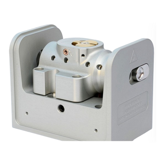
[1–3]. Rather than the customary diffraction grating of Littrow-configuration s, a high efficiency ultranarrow filter ECDL Figure 1.1: Inside the MOGLabs cateye laser. -
Page 14: External Cavity
Chapter 1. Introduction is used to select a single external cavity mode. Without the need for illuminating a large area of a grating for feedback, a cat-eye retroreflector and partially transmitting output coupler can be used to form the external cavity. The cateye reflector is inherently self- aligning, so that the laser is extremely insensitive to mechanical disturbance, and also ensures high feedback coupling efficiency and consequently narrow linewidth. -
Page 15: Mode Competition
1.2 Mode competition ternal cavity determines the lasing wavelength. The external cavity is typically around 40 mm long from rear facet of semiconductor to of /2L = 3 to output coupler, giving a cavity mode spacing (FSR) 4 GHz. The laser diode and collimating lens are held rigidly in a focusing tube. -
Page 16: Temperature And Current
Chapter 1. Introduction Diode cavity External cavity Diode gain Filter COMBINED 384.0 384.1 384.2 384.3 384.4 Frequency (THz) Figure 1.3: Schematic representation for the various frequency-dependent , adapted from Ref. [4], for wavelength λ = 780 nm and factors of an ECDL external cavity length L ext = 15 mm. -
Page 17: First Light
2. First light Initial installation of the laser is typically a matter of mounting it to an optical table and connecting to a abs controller. The MOGL laser can be mounted to posts using the M3 threaded holes on the base, or by removing the cover and screwing directly to the optical table using the M6x25 socket head cap screws provided. -
Page 18: Temperature
Chapter 2. First light It is assumed that a controller will be used to drive MOGL the laser. If an alternative supply is used, note that +5 V must be provided on pin 15 of the headboard connector to open the protective relay. -
Page 19: Current
2.2 Current 2.2 Current The output of semiconductor laser diodes follow a nominally linear power vs. current relationship, once the current is above a device- specific threshold (see Fig. 2.1). Initially the current should be set above threshold, but well below the nominal maximum operating current, until the laser is fully aligned. - Page 20 Chapter 2. First light...
-
Page 21: Operation
3. Operation Normal operation of the laser is usually a matter of adjusting the filter rotation angle to select the correct wavelength, and adjust- ing the piezo offset, diode injection current and bias to achieve the maximum possible mode-hop free scan. 3.1 Wavelength The primary control of wavelength is the filter rotation angle, which can be adjusted while the laser is operational. - Page 22 Chapter 3. Operation resolution spectrometer, or similar is almost essential, although with patience it is possible to find an atomic reference by carefully ad- justing the filter angle while scanning the laser. To change the wavelength: 1. Unlock the filter so that it can rotate, by turning the lock screw anti-clockwise, for example one full turn.
-
Page 23: Scanning
3.2 Scanning 3.2 Scanning The external cavity length is controlled by piezo actuators moving the output coupler. The cavity length increases with increasing volt- age on the piezos, thus decreasing the laser frequency. For a large frequency change, the laser will usually hop to a neighbouring cavity mode (see Fig. -
Page 24: External Modulation
Chapter 3. Operation This shift of cavity mode frequency allows for compensation of the mismatch of tuning responses. The diode injection current can be “automatically” adjusted as the laser frequency is changed, using a “feed-forward” or current bias which changes as the piezo voltage is changed. -
Page 25: Alignment
4. Alignment The cateye reflector arrangement is self-aligning, and should not require adjustment. However, laser diodes have a finite lifetime, and diode replacement may necessitate alignment of the internal optics, in particular the diode collimation and cateye lenses. For longer wavelength lasers, an infra-red upconversion card or camera can be very helpful. - Page 26 Chapter 4. Alignment 5.6mm diode 9mm diode Figure 4.1: Lens tube assembly with diode, lens, and mounting hardware. The same tube can be used for 5.6 mm and 9 mm diodes. Figure 4.2: Lens tubes. does not contact the diode. Also ensure the lens is tight; if not, use tape on the lens threads.
-
Page 27: Initial Diode Test
4.2 Initial diode test 9. Rotate the collimation assembly and adjust the alignment screws until the beam remains reasonably well on-axis. 10. Tighten the retaining ring (hard) and re-check that the diode remains aligned. 11. Focus the collimation lens such that the laser focuses to a spot at 4 m distance. -
Page 28: Cateye Reflector
Chapter 4. Alignment Filter θ From diode Figure 4.3: Orientation of the diode laser beam ellipse with respect to the filter rotation, for TM polarised diode, oriented with -plane polarisation. Some diodes, particularly around 750 to 820 nm, are TM polarised, with polarisation parallel to the long axis of the ellipse, as shown in Fig. - Page 29 4.4 Cateye reflector 15mm Lens tube Cateye Recollimator Figure 4.4: Arrangement of lens tube and cateye reflector for adjustment of focus of cateye. back which tends to lower the overall gain threshold. Repeat ECDL until the minimum is obtained. The sequence is as follows: 1.
- Page 30 Chapter 4. Alignment with one or more mode-hops. A Fabry-Perot etalon or a fast high-resolution wavemeter ( ) can also be used MOGL to optimise the mode-hop-free range. 8. Adjust the filter angle, and the injection current, to optimise the scans so that you see the maximum number of repeats and the deepest signals.
-
Page 31: A Specifications
A. Specifications Specification Parameter Wavelength/frequency 50 mW standard. 780 nm Up to 250 mW output power available. Please contact abs for availability. MOGL 369.5 – 1120 nm Typically < 150 kHz Linewidth 0.3 nm bandpass Filter Typically 10 nm for single diode Tuning range Sweep/scan 5 to 20 GHz depending on piezo... - Page 32 Appendix A. Specifications Specification Parameter Thermal ±14 5 V 3 3 A Q = 23 W standard NTC 10 kΩ standard; AD590, 592 optional Sensor ±1 mK (controller dependent) Stability at base Optional: 4 mm diam quick-fit water cooling Cooling connections Electronics Diode short-circuit relay;...
-
Page 33: Rf Response
response response The standard B1047 headboard includes active modulation with bandwidth of 10 MHz, either coupled. Alternately, the laser can be supplied with an internal bias tee, with typical frequency response shown below. RBW 30 kHz -30 dBm VBW 10 MHz Ref -20 dBm 50 dB SWT 17 s... -
Page 34: Mechanical
Appendix A. Specifications A.2 Mechanical 50.52 4 x M4 tapped 4 x M6 clearance Figure A.2: Dimensions of laser head. -
Page 35: B Laser Head Board
B. Laser head board The laser head interface board provides connection breakout to the laser diode, , sensor, piezo actuators, and laser head interlock. It also includes a solid-state protection relay and passive protection filters, a laser-on indicator, and an connection for direct diode current modulation. -
Page 36: B1045/1046 Headboard
They provide an input for direct diode modulation via an bias tee (see B.4 below). Figure B.1: MOGLabs B1045 and B1046 laser head boards showing connectors for laser diode, piezo actuator, temperature sensors, head enclosure interlock. -
Page 37: B1047/B1240 Headboards
B.2 B1047/B1240 headboards B.2 B1047/B1240 headboards The B1047 and B1240 provide high-speed active modulation of the diode current. They use 500 MHz opamps and very low latency circuitry to reduce phase delay to around 12 ns for the B1240. The B1047 allows for closed-loop bandwidth of about 1.2 MHz while the B1240 can achieve about 4 MHz (in both cases, without phase advance). -
Page 38: Sma Input
Appendix B. Laser head board B.2.1 input The B1047/B1240 input provides coupling to an active modulation circuit. Note that connection to the input will reduce the diode current by about 1.6 mA (B1047) to 2.5 mA (B1240), with zero input voltage. B1047 B1240 ±2 0 V max... -
Page 39: Laser Connection
B.3 Laser connection B.3 Laser connection abs cable can be replaced with a standard digital MOGL DVI-D cable. There is a bewildering assortment of apparently similar Dual cables available; only high quality dual-link digital cables DVI-D should be used. WARNING: The connector is a standard LASER DVI-D Dual Link... - Page 40 Appendix B. Laser head board 2.5 GHz (see fig. A.1). Capacitor , either 47 nF or 100 pF, can be changed to adjust the low-frequency cutoff. For higher bandwidths, use an external bias-tee such as the Mini-Circuits ZFBT-4R2GW-FT between the head board and the diode. The input impedance is 10 k.
- Page 41 B.4 RF coupling RF high bandwidth connection to diode Figure B.4: MOGLabs laser head board schematic (B1040/1045). modulation low-pass cutoff frequency is determined by C4 and the diode impedance (∼ 50Ω).
- Page 42 Appendix B. Laser head board...
- Page 43 Bibliography [1] Daniel J. Thompson and Robert E. Scholten. Narrow linewidth tunable external cavity diode laser using wide bandwidth filter. Review of Scientific Instruments, 83(2):–, 2012. 1, 2 [2] X. Baillard, A. Gauguet, S. Bize, P. Lemonde, Ph. Laurent, A. Clairon, and P. Rosenbusch. Interference-filter-stabilized external-cavity diode lasers.
-
Page 44: References
[9] G. C. Bjorklund. Frequency-modulation spectroscopy: new method for measuring weak absorptions and dispersions. Opt. Lett., 5:15, 1980. 12 [10] R. W. P. Drever, J. L. Hall, F. V. Kowalski, J. Hough, G. M. Ford, A. J. Munley, and H. Ward. Laser phase and frequency stabilization using an optical resonator. - Page 46 2014 – 2017 MOG Laboratories Pty Ltd 49 University St, Carlton VIC 3053, Australia Product specifications and descriptions in this doc- Tel: +61 3 9939 0677 info@moglabs.com ument are subject to change without notice.
Need help?
Do you have a question about the CEL002 and is the answer not in the manual?
Questions and answers