Table of Contents
Advertisement
Quick Links
Advertisement
Table of Contents

Subscribe to Our Youtube Channel
Related Manuals for MOGlabs CEL


Summary of Contents for MOGlabs CEL
- Page 1 Cateye Laser CEL, CEX and CEF Revision 2.01 Serial numbers A323xxxxx...
- Page 2 MOGL abs. Contact For further information, please contact: MOG Laboratories P/L MOGLabs USA LLC 49 University St 419 14th St Carlton VIC 3053 Huntingdon PA 16652 AUSTRALIA +61 3 9939 0677 +1 814 251 4363 info@moglabs.com...
- Page 3 Please let us know if you have any suggestions for improvement in the laser or in this document, so that we can make life in the laser lab easier for all, and check our website from time to time for updated information. MOGL abs, Melbourne, Australia www.moglabs.com...
- Page 5 PERFORMANCE OF PROCEDURES OTHER THAN THOSE SPECIFIED HEREIN MAY RESULT IN HAZARDOUS RADIATION EXPOSURE Laser output from the CEL/CEX/CEF can be dangerous. Please ensure that you implement the appropriate hazard minimisations for your environment, such as laser safety goggles, beam blocks, and door interlocks.
- Page 6 The unit should not be operated with covers removed. CAUTION Although the CEL/CEX/CEF is designed and priced with the expecta- tion that the end-user can replace the diode and change the align- ment, some components are fragile. In particular the filter, piezo actuator, and output coupler are very easily damaged.
- Page 7 Model number: Serial number: A32305001 Manufactured: MAY 2023 US FDA compliance Complies with 21 CFR 1040.10, and 1040.11 except for deviations pursuant to Laser Notice No.50, dated 24 June 2007 MOG Laboratories Pty Ltd, 49 University St Carlton VIC 3053, AUSTRALIA AVOID EXPOSURE Aperture label engraving LASER RADIATION IS...
- Page 8 Emission indicator INVISIBLE LASER RADIATION AVOID EXPOSURE TO BEAM CLASS 3B LASER PRODUCT Model number: Serial number: Wavelength Max Power A32305001 IEC 60825-1:2007 750 – 790 nm 200 mW Manufactured: AS/NZS 2211.5:2006 MAY 2023 Complies with 21 CFR 1040.10, and 1040.11 except for deviations pursuant to Laser Notice No.50, dated 24 June 2007 MOG Laboratories Pty Ltd, 49 University St Carlton VIC 3053, AUSTRALIA...
- Page 9 INVISIBLE LASER RADIATION AVOID EXPOSURE TO BEAM CLASS 3B LASER PRODUCT Wavelength Max Power IEC 60825-1:2007 750 – 790 nm 200 mW AS/NZS 2211.5:2006 Emission indicator Model number: Serial number: A32305001 Manufactured: MAY 2023 Complies with 21 CFR 1040.10, and 1040.11 except for deviations pursuant to Laser Notice No.50, dated 24 June 2007 MOG Laboratories Pty Ltd, 49 University St Carlton VIC 3053, AUSTRALIA...
- Page 10 Protection Features MOGL abs lasers includes a number of features to protect you and your laser. Protection relay When the power is off, or if the laser is off, the laser diode is shorted via a normally-closed solid-state relay at the laser head board. Emission indicator The MOGL abs controller will illuminate the emission warning indi-...
- Page 11 RoHS Certification of Conformance MOG Laboratories Pty Ltd certifies that the MOGL abs External Cavity Diode Laser does not fall under the scope defined in RoHS Directive 2002/95/EC, and is not subject to compliance, in accordance with DIREC- TIVE 2002/95/EC Out of Scope; Electronics related; Intended application is for Monitoring and Control or Medical Instrumentation.
- Page 12 Extending laser diode and piezo lifetime At night, switch to standby: 1. If using the laser to seed an amplifier, first turn off the amplifier. 2. Switch the laser diode current off. If using a MOGL controller, don’t adjust the current, just switch the toggle up (off).
-
Page 13: Table Of Contents
Contents Preface Safety Protection Features viii RoHS Certification of Conformance Extending laser diode & piezo lifetime 1 Introduction 1.1 External cavity ......1.1.1 Filter . - Page 14 A Specifications A.1 CEL mechanical (Rev9+) ....A.2 CEX/CEF mechanical ..... .
-
Page 15: Introduction
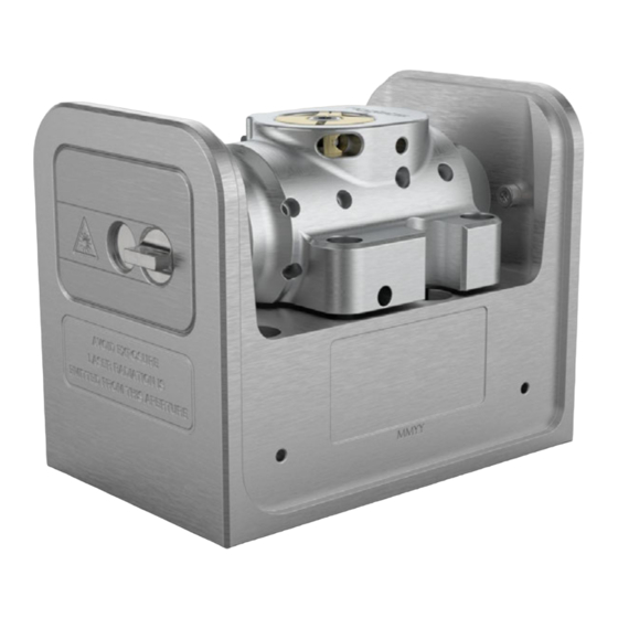
fluctuations and drift. The cateye laser block is mounted on a standard chassis ( ) or an extended chassis ( ) which can optionally include a fibre output ( Figure 1.1: The MOGLabs cateye laser. Mechanical version from 2023 shown (serial A323xxxxx and above). -
Page 16: External Cavity
Chapter 1. Introduction MOGL CEL/CEX/CEF is a “cat-eye” design (see figure 1.2), in which an external cavity is formed between the rear reflecting surface of the semiconductor diode, and a cat-eye reflector at several centimetres from the diode [1–3]. Rather than the customary diffraction grating of Littrow- configuration... -
Page 17: Filter
1.2 Piezo-electric frequency control by the OC and the diode rear facet, and when the external feedback is greater than that of the front facet, the external cavity determines the lasing wavelength. The effective external cavity is 20 to 40 mm long with of /2 L = 3.5 to 7 GHz. -
Page 18: Temperature And Current
Chapter 1. Introduction 1.3 Temperature and current The laser frequency is also dependent on temperature and injection cur- rent; the sensitivities are typically 3 MHz/µA and 30 GHz/K [4]. Thus, low-noise stable electronics, such as the external cavity MOGL diode laser controller, are essential [5] to achieve sub-MHz linewidth and stability. -
Page 19: First Light
2. First light Mount your laser to an optical table using the screws provided. Your laser has been carefully tuned to the specifications given in your laser test report. Please make sure as you continue with this manual, that the diode injection current, temperature and piezo offset ( FREQUENCY ) match... -
Page 20: Temperature
Chapter 2. First light ensures that the current is ramped up slowly and safely to the required current. However, when first aligning the laser to your experiment, it is important to set the laser output power to a low value for safety. Adjust the diode current to 5 –... - Page 21 2.3 Temperature Bare 150mW diode 780.243nm Extracavity estimate Injection current (mA) Figure 2.1: Sample laser diode power-current characteristic curves, with and without an external cavity. The output power of a diode with an anti-reflection coating is typically low. The steps in the power curve are caused my variation in the frequency of the external cavity relative to the diode intrinsic cavity mode, and/or to the filter transmission peak.
- Page 22 Chapter 2. First light...
-
Page 23: Operation
3. Operation Your laser has been carefully tuned to the specifications provided in the laser test report. In most cases, the laser will perform as expected once the current, temperature and piezo settings are adjusted to those in the test report. 3.1 Power and compare the output power from the laser power vs. -
Page 24: Mode-Hops
Chapter 3. Operation λ adjust Filter notch Spring plunger Filter assembly (spindle) Filter assembly (clamp) Spindle-clamp lock screw Figure 3.1: Filter angle adjustment, showing the primary wavelength adjustment screw and counter-acting spring plunger. Mechanical version from 2023 shown (serial A323xxxxx and above). After the target wavelength has been achieved, SPAN can be adjusted to... - Page 25 3.3 Mode-hops As the laser wavelength is varied, usually by changing the cavity length with a piezo, competition between the wavelength determined by the dif- ferent wavelength-dependent cavity elements can lead to a mode hop: a jump in laser wavelength to a different external cavity mode. Wavelength- dependent elements include the external cavity, the laser diode internal cavity between the rear and front facets of the diode, the filter, and the gain bandwidth of the laser diode.
-
Page 26: Scanning
Chapter 3. Operation 3.4 Scanning The external cavity length is controlled by a piezo actuator moving the external cavity mirror.The cavity length changes with piezo voltage, and for a large change, the laser will usually hop to a neighbouring cavity mode. -
Page 27: Faraday Isolator Alignment
3.5 Faraday isolator Time (0.4 sec/div) Figure 3.4: Laser frequency vs. time for a laser with a 4Hz piezo ramp rate, giving about 10 GHz of cavity frequency change when scanning mode-hop-free properly (left) and with a mode-hop at one edge (right). Figure 3.5: Extended chassis option, which adds two coupling mirrors and fibre output to the extended chassis option... - Page 28 Chapter 3. Operation The extended chassis version of a MOGL abs laser allows internal mounting of a Faraday isolator (see figure 3.6). Alignment is straightforward: the isolator should be concentric with the laser beam, and rotated axially so that the first polariser is parallel to the polarisation of the input laser beam.
- Page 29 3.5 Faraday isolator λ/2 waveplate λ/2 waveplate 0.035” or 0.9mm hex key Figure 3.7: Two types of single-stage Faraday isolator. Each can be supplied with λ/2 waveplate inside the exit end-cap. The waveplate can be rotated to rotate the plane of polarisation of the exit beam, for example to optimise coupling into polarisation maintaining fibre, or to adjust the ratio of exit beams for lasers fitted with a polarising beamsplitter instead of mirror M2.
- Page 30 Chapter 3. Operation...
-
Page 31: Troubleshooting
4. Troubleshooting 4.1 Scanning adjustment Achieving a wide continuous mode-hop free wavelength scan requires care- ful optimisation of the control parameters, including laser diode current, piezo offset, and feed-forward current bias (see § 4.1.1). The laser has been carefully tuned to the wavelength and scan range specified in the laser test report. -
Page 32: Bias Optimisation
Chapter 4. Troubleshooting 4.1.1 BIAS optimisation Ideally the frequencies of the external cavity mode and the intrinsic laser diode mode are synchronised as the laser frequency is varied (see fig- ure 3.2). The external mode frequency is controlled by the piezo. The intrinsic diode mode frequency can be controlled by adjusting the laser diode current. - Page 33 4.1 Scanning adjustment lasing mode. If more significant wavelength adjustment is required, mechanically rotate the filter (see § 4.2). 5. If the wavelength is within a few picometres (GHz) of the target, increase SPAN while observing the wavelength scan as shown in figure 3.4.
-
Page 34: Filter Adjustment
Chapter 4. Troubleshooting 4.2 Filter adjustment This section contains mechanical details that apply only to serial num- bers A323xxxxx and above. For older cateye lasers, refer to the appro- priate manual prior to version 2.01. The primary control of wavelength is the filter rotation angle, which can be adjusted while the laser is operational. -
Page 35: Threshold Optimisation
4.3 Threshold optimisation For adjustments of less than 1nm: 6. Check that the spring-plunger is engaged but not locked against the brass arm of the spindle clamp. That is, the pin should be visibly protruding from the spring-plunger screw, and touching the brass arm. - Page 36 Chapter 4. Troubleshooting The lasing threshold, at which the overall gain exceeds losses, should be as low as possible to maximise the output power and also the scan range and frequency stability. The lowest threshold is achieved by optimising the focus of the laser diode collimation lens and of the cateye lens (see figure 4.1).
- Page 37 4.3 Threshold optimisation 4. Remove the brass clamp from the central spindle, then remove the three hex drive screws holding the circular plate on top of the spindle (see figure 4.2). Figure 4.2: Removing the intracavity filter assembly. a) Three screws hold the top plate (pink) over the spindle.
-
Page 38: Fibre Coupling
Chapter 4. Troubleshooting the cateye lens, using the focus adjust tool provided with your laser, or a small screwdriver, until the power increases to a peak. 10. Reduce the injection current to obtain 1 mW, followed by focus ad- justment of the cateye lens, and iterate until the minimum current threshold is achieved. -
Page 39: Reverse Beam: Using A Visual Fault Locator
4.4 Fibre coupling fibre, and the mirrors adjusted so that the beam is clearly transmitted by the coupler (see below for detailed instructions). An eccentric key is provided for adjusting the coupling lens focus. Please contact MOGL abs if your fibre coupling efficiency is much lower than stated in your laser test report. - Page 40 Chapter 4. Troubleshooting 1. Adjust the laser current so that the output power is around 5 to 10 mW. 2. If some power is detected exiting from the fibre, skip to step 9 below. 3. If the fibre coupler is not yet installed, first coarsely adjust the mir- rors so that the beam exits through the centre of the fibre coupler mount, and parallel to the long axis of the laser chassis.
- Page 41 4.4 Fibre coupling only 5 to 10% or less. Take note of roughly how much rotation was required, so you can easily return to the original position. 12. Adjust the horizontal axis of mirror M1 and maximise for output power. Compare the new maximum output power to the output power obtained at step 10.
- Page 42 Chapter 4. Troubleshooting...
-
Page 43: A Specifications
A. Specifications Parameter Specification Wavelength/frequency 368 – 1620 nm Diode dependent. Please contact MOGL abs for availability. Typically < 100 kHz Linewidth Filter 0.2 to 0.4 nm bandpass Tuning range Diode dependent; 5 nm to 50 nm Sweep/scan Scan range 20 to 30 GHz Mode-hop free 5 to 30 GHz... - Page 44 Appendix A. Specifications Parameter Specification Thermal ±14 5 V 3 3 A Q = 23 W standard Sensor NTC 10 kΩ standard; AD590, 592 optional ±1 mK (controller dependent) Stability at base Cooling Optional: 4 mm diam quick-fit water cooling connections Electronics Protection...
-
Page 45: Cel Mechanical (Rev9+)
A.1 CEL mechanical (Rev9+) A.1 CEL mechanical (Rev9+) 50.5 4 x M6 clearance Figure A.1: Dimensions of laser head (Rev9+). -
Page 46: Cex/Cef Mechanical
Appendix A. Specifications A.2 CEX/CEF mechanical 92.6 27.5 27.5 75.0/76.2 200/201.2 74.2/75.0 Figure A.2: Dimensions of laser head. -
Page 47: B Laser Head Board
B. Laser head board The laser head interface board provides connection breakout to the laser diode, , sensor, piezo actuators, and laser head interlock. It also in- cludes a protection relay and passive protection filters, a laser-on indicator, and an connection for direct diode current modulation. -
Page 48: B1045/1046 Headboard
They provide an input for direct diode modulation via an bias tee (see B.1.1 below). Figure B.1: MOGLabs B1045 and B1046 laser head boards showing connectors for laser diode, piezo actuator, temperature sensors, and head enclosure interlock. Connectors are Hirose DF59. - Page 49 B.1 B1045/1046 headboard The input impedance is 10 kΩ. The sensitivity depends on the diode impedance but is typically around 1 mA/V. WARNING: The input is a direct connection to the laser diode. Exces- sive power can destroy the diode, which is separated from the head board relay by an inductor.
-
Page 50: B1047/B1240 Headboards
Appendix B. Laser head board B.2 B1047/B1240 headboards The B1047 and B1240 provide high-speed active modulation of the diode current. They use 500 MHz opamps and very low latency circuitry to re- duce phase delay to around 12 ns for the B1240. The B1047 allows for closed-loop bandwidth of about 1.2 MHz while the B1240 can achieve about 4 MHz (in both cases, without phase advance), which is helpful in achieving sub-Hz linewidth reduction by locking to a high-finesse optical... -
Page 51: Sma Input
B.2 B1047/B1240 headboards B.2.1 input The B1047/B1240 input provides coupling to an active modulation circuit. Note that connection to the input will reduce the diode current by about 1.6 mA (B1047) to 2.5 mA (B1240), with zero input voltage. B1047 B1240 ±2 0 V max ±2 0 V max... -
Page 52: Headboard Connection To Controller
Appendix B. Laser head board B.3 Headboard connection to controller Note (dual link) cable. There MOGL abs laser cable is a digital DVI-D DL is a bewildering assortment of apparently similar cables available. Most computer display cables will not work because they are missing impor- tant pins;... - Page 53 Cover interlock (option) (+5v in) s i s Figure B.5: MOGLabs laser head board schematic (B1040/1045). The modulation low-pass cutoff frequency is determined by C4 and the diode impedance (∼ 50Ω).
- Page 54 Appendix B. Laser head board...
-
Page 55: References
Bibliography [1] Daniel J. Thompson and Robert E. Scholten. Narrow linewidth tunable external cavity diode laser using wide bandwidth filter. Review of Scientific Instruments, 83(2):–, 2012. 2 [2] X. Baillard, A. Gauguet, S. Bize, P. Lemonde, Ph. Laurent, A. Clairon, and P. - Page 58 MOG Laboratories Pty Ltd © 2014 – 2023 49 University St, Carlton VIC 3053, Australia Product specifications and descriptions in this docu- Tel: +61 3 9939 0677 info@moglabs.com ment are subject to change without notice.
Need help?
Do you have a question about the CEL and is the answer not in the manual?
Questions and answers