Table of Contents
Advertisement
Quick Links
Advertisement
Table of Contents

Related Manuals for MOGlabs CEL


Summary of Contents for MOGlabs CEL
- Page 1 External Cavity Diode Laser CEL, CEX and CEF Cateye Revision 1.21...
- Page 2 MOGL abs. Contact For further information, please contact: MOG Laboratories P/L MOGLabs USA LLC 49 University St 419 14th St Carlton VIC 3053 Huntingdon PA 16652 AUSTRALIA +61 3 9939 0677 +1 814 251 4363 info@moglabs.com...
- Page 3 MOGL abs, Melbourne, Australia www.moglabs.com...
- Page 5 Safety Precautions Safe and effective use of this product is very important. Please read the following laser safety information before attempting to operate the laser. Also please note several specific and unusual cautionary notes before using MOGL abs lasers, in addition to the safety precautions that are standard for any electronic equipment or for laser-related instrumentation.
- Page 6 • To completely shut off power to the unit, turn the keyswitch anti- clockwise ( position), switch the mains power switch at rear STANDBY of unit to , and unplug the unit. • When the STANDBY keyswitch is on STANDBY , there cannot be power to the laser diode, but power is still being supplied to the laser head for temperature control.
- Page 7 Model number: Serial number: A31907001 Manufactured: JULY 2019 US FDA compliance Complies with 21 CFR 1040.10, and 1040.11 except for deviations pursuant to Laser Notice No.50, dated 24 June 2007 MOG Laboratories Pty Ltd, 49 University St Carlton VIC 3053, AUSTRALIA AVOID EXPOSURE Aperture label engraving LASER RADIATION IS...
- Page 8 Emission indicator INVISIBLE LASER RADIATION AVOID EXPOSURE TO BEAM CLASS 3B LASER PRODUCT Model number: Serial number: Wavelength Max Power A31907001 IEC 60825-1:2007 750 – 790 nm 200 mW Manufactured: AS/NZS 2211.5:2006 JULY 2019 Complies with 21 CFR 1040.10, and 1040.11 except for deviations pursuant to Laser Notice No.50, dated 24 June 2007 MOG Laboratories Pty Ltd, 49 University St Carlton VIC 3053, AUSTRALIA...
- Page 9 INVISIBLE LASER RADIATION AVOID EXPOSURE TO BEAM CLASS 3B LASER PRODUCT Wavelength Max Power IEC 60825-1:2007 750 – 790 nm 200 mW AS/NZS 2211.5:2006 Emission indicator Model number: Serial number: A31907001 Manufactured: JULY 2019 Complies with 21 CFR 1040.10, and 1040.11 except for deviations pursuant to Laser Notice No.50, dated 24 June 2007 MOG Laboratories Pty Ltd, 49 University St Carlton VIC 3053, AUSTRALIA...
- Page 10 Protection Features MOGL abs lasers includes a number of features to protect you and your laser. Protection relay When the power is off, or if the laser is off, the laser diode is shorted via a normally-closed solid-state relay at the laser head board. Emission indicator The MOGL abs controller will illuminate the emission warning indi-...
- Page 11 RoHS Certification of Conformance MOG Laboratories Pty Ltd certifies that the MOGL abs External Cavity Diode Laser does not fall under the scope defined in RoHS Directive 2002/95/EC, and is not subject to compliance, in accordance with DIREC- TIVE 2002/95/EC Out of Scope; Electronics related; Intended application is for Monitoring and Control or Medical Instrumentation.
- Page 12 Extending laser diode and piezo lifetime At night, switch to standby: 1. If using the to seed an amplifier, first turn off the amplifier. 2. Switch the laser diode current off. If using a MOGL controller, don’t adjust the current, just switch the toggle up (off).
-
Page 13: Table Of Contents
Contents Preface Safety Protection Features viii RoHS Certification of Conformance Extending laser diode & piezo lifetime 1 Introduction 1.1 External cavity ......1.2 Piezo-electric frequency control . - Page 14 A Specifications A.1 CEL mechanical (Rev8) ..... A.2 CEL mechanical (Rev9) .....
-
Page 15: Introduction
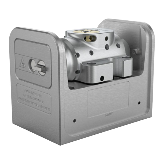
“cat-eye” design (see Fig. 1.2), in which an ex- ternal cavity is formed between the rear reflecting surface of the semi- conductor diode, and a cat-eye reflector at several centimetres from the Figure 1.1: The MOGLabs cateye laser. -
Page 16: External Cavity
Chapter 1. Introduction diode [1–3]. Rather than the customary diffraction grating of Littrow- configuration s, a high efficiency ultranarrow filter is used to select ECDL a single external cavity mode. Without the need for illuminating a large area of a grating for feedback, a cat-eye retroreflector and partially trans- mitting output coupler can be used to form the external cavity. -
Page 17: Piezo-Electric Frequency Control
1.2 Piezo-electric frequency control lasing wavelength. The external cavity is typically about 40 mm long from rear facet of semiconductor to output coupler, giving a cavity mode spacing of /2L = 4 GHz. (FSR) The laser diode and collimating lens are held rigidly in a focusing tube. The filter is fixed to a bearing-mounted rotation assembly with a fine thread screw to adjust the angle. - Page 18 Chapter 1. Introduction...
-
Page 19: First Light
2. First light Mount your laser to an optical table using the screws provided. Your laser has been carefully tuned to the specifications given in your laser test report. Please make sure as you continue with this manual, that the diode injection current, temperature and piezo offset ( FREQUENCY ) match... -
Page 20: Temperature
Chapter 2. First light up slowly and safely to the required current. When first aligning the laser to your experiment, it is important to set the laser output power to a low value for safety. Adjust the diode current to 5 – 10 mA and check that the diode voltage VOLTAGE selection on main control knob on ) is the same as listed in the... - Page 21 2.3 Temperature Bare 150mW diode 780.243nm Extracavity estimate Injection current (mA) Figure 2.1: Sample laser diode power-current characteristic curves, with and without an external cavity. The output power of a diode with an anti-reflection coating is typically low. The steps in the power curve are caused my variation in the frequency of the external cavity relative to the diode intrinsic cavity mode, and/or to the filter transmission peak.
- Page 22 Chapter 2. First light...
-
Page 23: Operation And Optimisation
3. Operation and Optimisation Your laser has been carefully tuned to the specifications provided in the laser test report. Check that current, temperature and piezo settings match the values in the test report. This chapter provides instructions on how to operate and optimise the MOGL abs laser system. -
Page 24: Mode-Hops
Chapter 3. Operation and Optimisation Spring plunger Filter notch Spindle-clamp lock screw Filter assembly (clamp) Filter assembly (spindle) λ adjust λ lock screw Figure 3.1: Filter angle adjustment, showing the primary wavelength adjustment screw and counter-acting spring plunger. 3.3 Mode-hops Mode-hops are a frequent occurrence with external cavity diode lasers. -
Page 25: Scanning
3.4 Scanning cally in figure 3.2. The net gain is the product of semiconductor gain, filter transmission, internal and external cavity interference. The net gain can be very similar at adjacent external cavity modes. A small change in the laser cavity optical path length, the diode internal cavity mode frequency, or the filter angle, can lead to the overall gain being greater at a mode adjacent to the mode in which the laser is oscillating, and the laser then hops to that higher-gain mode. -
Page 26: Faraday Isolator
Chapter 3. Operation and Optimisation -200 -100 Frequency (GHz) Figure 3.3: Combined gain for an external cavity diode laser, including the in- ternal and external modes, the diode laser gain, and the filter response. The broad feature is the frequency selectivity of the filter, and the smaller peaks are the external cavity modes (see fig. -
Page 27: Faraday Isolator Alignment
3.5 Faraday isolator Figure 3.4: Frequency of a laser scanning properly (left) and with a mode-hop at one edge (right). Figure 3.5: Extended chassis option, shown here with cateye installed. 3.5.1 Faraday isolator alignment Faraday isolators are critical to the stability of an external cavity diode laser. - Page 28 Chapter 3. Operation and Optimisation with 90 to 95% typical at 780 nm. Fibre coupler Cylindrical telescope Faraday isolator Figure 3.6: Schematic of the extended chassis laser showing Faraday isolator, and two mirrors used for aligning the beam to a single-mode fibre. ◦...
- Page 29 3.5 Faraday isolator λ/2 waveplate λ/2 waveplate 0.035” or 0.9mm hex key Figure 3.7: Two types of single-stage Faraday isolator. Each can be supplied with exit λ/2 waveplate inside one end-cap. The waveplate can be rotated to rotate the plane of polarisation of the exit beam, for example to optimise coupling into polarisation maintaining fibre, or to adjust the ratio of exit beams for lasers fitted with a polarising beamsplitter instead of mirror M2.
- Page 30 Chapter 3. Operation and Optimisation...
-
Page 31: Troubleshooting
4. Troubleshooting 4.1 Scanning adjustment Achieving a wide continuous mode-hop free wavelength scan requires care- ful optimisation of the control parameters, including laser diode current, piezo offset, and feed-forward current bias. The laser has been carefully tuned to the wavelength and scan range specified in the laser test report. The instructions below describe how to achieve the maximum mode-hop free range (MHFR). -
Page 32: Bias Optimisation
Chapter 4. Troubleshooting 4.1.1 BIAS optimisation Ideally the frequencies of the external cavity mode and the intrinsic laser diode mode are identical (see fig. 3.2). The external mode frequency is con- trolled by the piezo. The intrinsic diode mode frequency can be controlled by adjusting the laser diode current. -
Page 33: Filter Adjustment
4.2 Filter adjustment 6. Increase SPAN until a mode-hop is evident. If using absorption spec- troscopy to monitor the laser wavelength, it can be helpful to observe the derivative, for example the demodulated error signal ( CHAN BError on a MOGL The mode hop should be at one edge of the scan;... - Page 34 Chapter 4. Troubleshooting WARNING: Ensure that the filter is never perpendicular to the laser axis ◦ (filter angle 0 , notch horizontal in fig. 3.1) if the diode is powered on. The filter is a highly reflective mirror that will back-reflect light into the diode, which can cause catastrophic damage.
-
Page 35: Threshold Optimisation
4.3 Threshold optimisation 9. Once the laser is operating near the desired wavelength, adjust the diode current and the piezo voltage to achieve the exact wavelength required. If the CURRENT adjustment has shifted the wavelength to a mode further away from the desired wavelength, use the fine screw adjustment method to correct the wavelength. - Page 36 Chapter 4. Troubleshooting The sequence is as follows: 1. Ensure the is off or on standby. 2. Take note of the filter angle by marking on the laser barrel the alignment of the filter assembly notch relative to the laser barrel notch.
- Page 37 4.3 Threshold optimisation 7. Lift the brass clamp and filter spindle clear of the laser barrel. Ex- cessive force should not be required. If the filter seems stuck, it may be caught on the cateye output coupler or laser diode tubes. In that case, it will be necessary to slide the cateye output coupler tube, and/or laser diode lens tube, away from the filter assembly.
-
Page 38: Fibre Coupling Adjustment
Chapter 4. Troubleshooting 10. Adjust the injection current to just below threshold. 11. Adjust the cateye lens focus until a bright flash (i.e. lasing) is ob- served. 12. Iterate reduction of the injection current, following by focus of the cateye, until the minimum threshold is achieved. 13. -
Page 39: Reverse Beam: Using A Visual Fault Locator
4.4 Fibre coupling adjustment 4.4.1 Reverse beam: using a visual fault locator A visual fault locator is a very useful device for quickly achieving initial coupling of the laser beam to the fibre. A visual fault locator (see fig. 4.4) is a low-power red laser that injects a beam into the exit end of the fibre patchcord, thus propagating visible light backwards along the fibre and then into free space, forming a beam back into the laser cavity. - Page 40 Chapter 4. Troubleshooting mount, and parallel to the long axis of the laser chassis. Then install the coupler. 4. If some power is detected exiting from the fibre, skip to step 9 below. 5. With fibre patchcord removed, adjust the mirrors so that the beam exits from the fibre coupler cleanly.
- Page 41 4.4 Fibre coupling adjustment 14. Once horizontal alignment is optimised, repeat the procedure but using vertical adjustments. 15. Iterate horizontal and vertical alignment until coupling efficiency is fully optimised. As optimum coupling is approached, the adjustments should be reduced at each step. 16.
- Page 42 Chapter 4. Troubleshooting...
-
Page 43: A Specifications
A. Specifications Parameter Specification Wavelength/frequency 370 – 1620 nm Diode dependent. Please contact MOGL abs for availability. Typically < 100 kHz Linewidth Filter 0.2 to 0.4 nm bandpass Tuning range Diode dependent; 5 nm to 50 nm Sweep/scan Scan range 20 to 30 GHz Mode-hop free 5 to 30 GHz... - Page 44 Appendix A. Specifications Parameter Specification Thermal ±14 5 V 3 3 A Q = 23 W standard Sensor NTC 10 kΩ standard; AD590, 592 optional ±1 mK (controller dependent) Stability at base Cooling Optional: 4 mm diam quick-fit water cooling connections Electronics Protection...
-
Page 45: Cel Mechanical (Rev8)
A.1 CEL mechanical (Rev8) A.1 CEL mechanical (Rev8) 50.52 4 x M4 tapped 4 x M6 clearance Figure A.1: Dimensions of laser head (Rev8). -
Page 46: Cel Mechanical (Rev9)
Appendix A. Specifications A.2 CEL mechanical (Rev9) 50.5 4 x M6 clearance Figure A.2: Dimensions of laser head (Rev9+). -
Page 47: Cef Mechanical
A.3 CEF mechanical A.3 CEF mechanical 92.6 27.5 27.5 75.0-76.2 200-201.2 74.2-75.0 Figure A.3: Dimensions of laser head. - Page 48 Appendix A. Specifications...
-
Page 49: B Laser Head Board
B. Laser head board The laser head interface board provides connection breakout to the laser diode, , sensor, piezo actuators, and laser head interlock. It also in- cludes a protection relay and passive protection filters, a laser-on indicator, and an connection for direct diode current modulation. -
Page 50: B1045/1046 Headboard
They provide an input for direct diode modulation via an bias tee (see B.1.1 below). Figure B.1: MOGLabs B1045 and B1046 laser head boards showing connectors for laser diode, piezo actuator, temperature sensors, and head enclosure interlock. Connectors are Hirose DF59. - Page 51 B.1 B1045/1046 headboard The input impedance is 10 kΩ. The sensitivity depends on the diode impedance but is typically around 1 mA/V. WARNING: The input is a direct connection to the laser diode. Exces- sive power can destroy the diode, which is separated from the head board relay by an inductor.
-
Page 52: B1047/B1240 Headboards
Appendix B. Laser head board B.2 B1047/B1240 headboards The B1047 and B1240 provide high-speed active modulation of the diode current. They use 500 MHz opamps and very low latency circuitry to re- duce phase delay to around 12 ns for the B1240. The B1047 allows for closed-loop bandwidth of about 1.2 MHz while the B1240 can achieve about 4 MHz (in both cases, without phase advance), which is helpful in achieving sub-Hz linewidth reduction by locking to a high-finesse optical... -
Page 53: Sma Input
B.2 B1047/B1240 headboards B.2.1 input The B1047/B1240 input provides coupling to an active modulation circuit. Note that connection to the input will reduce the diode current by about 1.6 mA (B1047) to 2.5 mA (B1240), with zero input voltage. B1047 B1240 ±2 0 V max ±2 0 V max... -
Page 54: Headboard Connection To Controller
Appendix B. Laser head board B.3 Headboard connection to controller Note (dual link) cable. There MOGL abs laser cable is a digital DVI-D DL is a bewildering assortment of apparently similar cables available. Most computer display cables will not work because they are missing impor- tant pins;... - Page 55 Cover interlock (option) (+5v in) s i s Figure B.5: MOGLabs laser head board schematic (B1040/1045). The modulation low-pass cutoff frequency is determined by C4 and the diode impedance (∼ 50Ω).
- Page 56 Appendix B. Laser head board...
- Page 57 Bibliography [1] Daniel J. Thompson and Robert E. Scholten. Narrow linewidth tunable external cavity diode laser using wide bandwidth filter. Review of Scientific Instruments, 83(2):–, 2012. 2 [2] X. Baillard, A. Gauguet, S. Bize, P. Lemonde, Ph. Laurent, A. Clairon, and P.
-
Page 58: References
[10] R. W. P. Drever, J. L. Hall, F. V. Kowalski, J. Hough, G. M. Ford, A. J. Munley, and H. Ward. Laser phase and frequency stabilization using an optical resonator. Appl. Phys. B, 31:97–105, 1983. [11] M. Zhu and J. L. Hall. Stabilization of optical phase/frequency of a laser system: application to a commercial dye laser with an external stabilizer. - Page 60 MOG Laboratories Pty Ltd © 2014 – 2022 49 University St, Carlton VIC 3053, Australia Product specifications and descriptions in this docu- Tel: +61 3 9939 0677 info@moglabs.com ment are subject to change without notice.
Need help?
Do you have a question about the CEL and is the answer not in the manual?
Questions and answers