
Related Manuals for MOGlabs MSA


Summary of Contents for MOGlabs MSA
- Page 1 Amplified laser system Model MSA – internal seed Model MOA/MOA(L)/MOA(C) – external seed Revision 2.00...
- Page 2 MOGL Contact For further information, please contact: MOG Laboratories P/L MOGLabs USA LLC 49 University St 419 14th St Carlton VIC 3053 Huntingdon PA 16652 AUSTRALIA +61 3 9939 0677 +1 814 251 4363 info@moglabs.com...
- Page 3 We are proud of our products and continuously improving them. Please let us know if you have any suggestions for enhancement of the product or this document, so that we can make life in the lab better for all. abs, Melbourne, Australia MOGL www.moglabs.com...
-
Page 5: Safety Precautions
Safety Precautions Your safety and the safety of your colleagues depends on careful atten- tion to proper operation of this product. Please read the following safety information before attempting to operate. Please note several specific and unusual cautionary notes before using the MOGL in addition to the safety precautions that are standard for any electronic equipment. - Page 6 • Note the safety labels (examples shown in figure 1) and heed their warnings. • The must be operated with a controller with keyswitch interlock. The must not be powered unless the keyswitch is inserted and switched on. It should not be possible to remove the keyswitch without turning off...
- Page 7 Label identification The International Electrotechnical Commission laser safety standard IEC 60825-1:2007 mandates warning labels that provide information on the wavelength and power of emitted laser radiation, and which show the aperture where laser radiation is emitted. Figures 1 and 2 show examples of these labels and their location on the Model number: MSA003...
- Page 8 FDA compliance and serial number Emission indicators Model number: MSA003 Serial number: A41706002 Manufactured: JUNE 2017 VISIBLE LASER RADIATION Complies with 21 CFR 1040.10, and 1040.11 except for AVOID EYE OR SKIN EXPOSURE TO deviations pursuant to Laser Notice No.50, dated 24 June 2007 DIRECT OR SCATTERED RADIATION MOG Laboratories Pty Ltd, 49 University St CLASS 4 LASER PRODUCT...
-
Page 9: Table Of Contents
2.2 Photodiode safety cutout ....3 First light 4 MSA: internal seed alignment 4.1 Small adjustment to seed alignment .... - Page 10 viii Contents A.1 Amplifier headboard: ....A.2 Connector pinouts ......B Chassis dimensions...
-
Page 11: Introduction
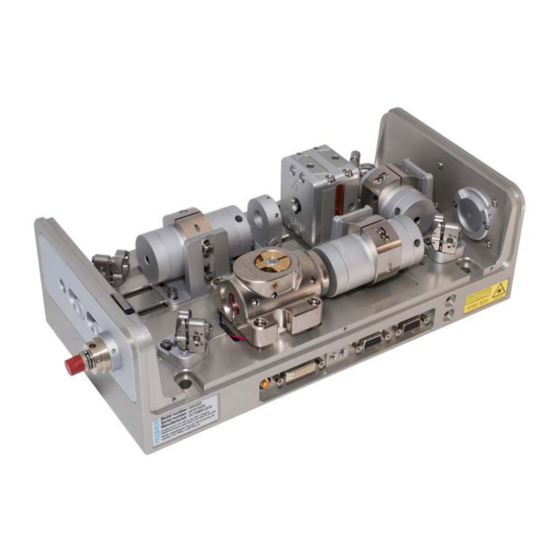
1. Introduction is a semiconductor laser amplifier with injection seed MOGL laser (fig. 1.1). The heart of the system is the amplifier block (fig. 1.2) with semiconductor tapered amplifier ( ) diode. A cylindrical lens provides astigmatism compensation and Faraday isolators protect the diode, as well as preventing the amplifier output from disturbing the seed laser. - Page 12 Chapter 1. Introduction stability. Finely threaded tubes control the lens positions along the axis of propagation. The U-chassis allows simple user replacement of the diode (see chapter 8). Lens focus Focus tools Flexure alignment screws & lock ring diode block (U-chassis), showing flexure alignment and focus Figure 1.2: adjustments for input and output lenses and tools for focus adjust and locking.
- Page 13 ) to pick off a fixed (or variable) free-space beam from the seed laser, which can be used for locking to a frequency reference or monitoring the seed laser. For the series, the seed beam enters through the input aperture either in free-space or via a fibre coupler, and is then deflected by mirrors into the diode.
- Page 14 Chapter 1. Introduction...
-
Page 15: Safety Features
Refer to the Maximum current, unseeded specified in the amplifier test report. MOGLabs amplifiers have interlocks for customer protection and internal power monitoring with a safety shutoff feature to protect the diode. - Page 16 Chapter 2. Safety features back from the cylindrical lens. The second location is in a separate mount with a dedicated fused silica beam-sampling optic. Please be aware that any changes in optical alignment that affect the output beam and/or reflected signal from the cylindrical lens will require re-calibration of the photodiode threshold as described in the user manual.
-
Page 17: First Light
3. First light WARNING Do not operate the amplifier above the Maximum current, unseeded without an appropriately coupled input seed. Operation exceeding that condition can cause fatal structural degradation of the diode. Refer to the Maximum current, unseeded specified in the amplifier test report. The initial installation is typically a matter of mounting the chassis to an optical table, checking the temperature stabilisation and... - Page 18 Chapter 3. First light indicated on the controllers and specified by in the system test re- port. Temperature stabilisation usually takes 5 to 10 minutes. De- tailed controller operation instructions are provided separately in their associated user manuals. 5. The injection current should be chosen to provide between 10 mW and 100 mW of output power, but no more than approximately 90% of the Maximum current, unseeded (refer to customer test report).
-
Page 19: Msa: Internal Seed Alignment
4. MSA: internal seed alignment WARNING Do not operate the amplifier above the Maximum current, unseeded without an appropriately coupled input seed. Operation exceeding that condition can cause fatal structural degradation of the diode. Refer to the Maximum current, unseeded specified in the amplifier test report. -
Page 20: Substantial Adjustment To Seed Alignment
Chapter 4. MSA: internal seed alignment 4. Power on the diode with an injection current of 100 mA less than the Maximum current, unseeded. Adjust the seed laser current/power so that it matches a listed value from the table Guide for seed cou- pling at low and high tapered amplifier current in the system test... - Page 21 4.2 Substantial adjustment to seed alignment ment, the diode has been replaced or under instruction by MOGL support. For most systems, optical element is a partially reflecting fixed- ratio beam-splitter. The transmitted part of the seed laser beam (location in fig. 4.1) can be used for the following steps in seed alignment. If is instead a mirror, the seed laser beam can be accessed by inserting a mirror directly after the seed laser (location in fig.
- Page 22 Chapter 4. MSA: internal seed alignment power and frequency, i.e. not near a mode-hop and not ramping the piezo. 5. The divergence of seed reverse propagating beams should be matched. Remove and the input side chassis endplate, or use a mirror to deflect the seed beam out of the chassis.
- Page 23 4.2 Substantial adjustment to seed alignment 9. Remove input isolator 2 (if installed between ), preferably by removing the entire isolator, ring clamp and right angle bracket as one assembly. First ensure the isolator inputs and outputs are covered to protect against items being magnetically attracted into the isolator optics.
- Page 24 Chapter 4. MSA: internal seed alignment (b) Install a power sensor after the output, preferably after the output isolator. (c) For the horizontal axis first, adjust to achieve maximum output power from the . Call this value (d) Make a small adjustment to the horizontal axis of...
- Page 25 4.2 Substantial adjustment to seed alignment 17. Once is optimised, adjust the orientation of the half-wave plate mounted in the endcap of the input isolator (see fig. 4.3) by first loosening the set screw indicated. Rotate the half-wave plate to maximise power out of the diode, then re-tighten the set screw.
- Page 26 Chapter 4. MSA: internal seed alignment...
- Page 27 4.2 Substantial adjustment to seed alignment Figure 4.2: Lens tube spanners for adjusting collimation lenses. λ/2 waveplate λ/2 waveplate 0.035” or 0.9mm hex key Figure 4.3: Schematic diagram showing location of half-wave plate in isolator endcaps. Ensure set screw is loosened before rotating endcap.
- Page 28 Chapter 4. MSA: internal seed alignment...
-
Page 29: Moa: External Seed Alignment
5. MOA: external seed alignment WARNING Do not operate the amplifier above the Maximum current, unseeded without an appropriately coupled input seed. Operation exceeding that condition can cause fatal structural degradation of the diode. Refer to the Maximum current, unseeded specified in the amplifier test report. installation requires aligning a seed laser with the diode to obtain a power comparable to the value in the... - Page 30 Chapter 5. MOA: external seed alignment OPTIONAL OPTIONAL FIBRE FIBRE INPUT OUTPUT OPTIONAL INPUT ISOLATOR OPTIONAL λ/2 TA DIODE OUTPUT LENS ISOLATOR Figure 5.1: Schematic diagram of major components in the to avoid normal incidence reflections. NOTE: If a sufficiently slim power sensor is not available, insert a mirror in the beam path after the output isolator (preferably, other- wise before the isolator) to deflect the beam to a larger sensor.
- Page 31 5.1 Seed alignment system test report, typically 10 mW (20 mW for some diodes). If an input isolator is installed in the , measure between that isolator and the diode. 5. The seed laser should be stable in power and frequency, i.e. not near a mode-hop and not ramping the piezo.
- Page 32 Chapter 5. MOA: external seed alignment installed, this distance will be quite short). To optimise the align- ment, use a walking procedure as follows, where refer to external mirrors in the case of MOA(C) (a) Make sure that the seed laser beam is incident and centred at block input aperture by adjusting (b) Ensure a power sensor is installed after the output, prefer-...
- Page 33 5.1 Seed alignment 9. Check that the seed laser power before the (position B in fig. 5.1) has not changed during the adjustment procedure and corresponds to the seed power from the system test report. If it has changed, again adjust the seed laser current so that the power at position B matches a listed value in the Guide for seed coupling at low and high tapered amplifier current table in the system test report.
-
Page 34: Reverse Propagating Ta Diode Beam Collimation
Chapter 5. MOA: external seed alignment 5.2 Reverse propagating diode beam collimation Please do not proceed with the block adjustment steps below unless there has been substantial misalignment or the diode has been replaced. 1. Block any seed light from entering the amplifier chassis. Referring to the Unseeded column in the test report table Guide for seed coupling at low and high tapered amplifier current, set the diode... - Page 35 5.2 Reverse propagating diode beam collimation 5. For the , re-install the input Faraday isolator, if installed. Make sure the seed laser beam propagates through the centre of the iso- lator input and output apertures without clipping. 6. Repeat the walking procedure from section 5.1, step 8, through to the end of the section.
- Page 36 Chapter 5. MOA: external seed alignment...
-
Page 37: Output Beam Optimisation
6. Output beam optimisation WARNING Do not operate the amplifier above the Maximum current, unseeded without an appropriately coupled input seed. Operation exceeding that condition can cause fatal structural degradation of the diode. Refer to the Maximum current, unseeded specified in the amplifier test report. The beam profile of a output beam generally looks unpleasant. -
Page 38: Procedure For Output Beam Optimisation
Chapter 6. Output beam optimisation movement of the cylindrical lens, adjustment of the output lens) or the diode has been replaced. It is non-trivial to achieve equivalent results as represented in the system test report, so seek advice from MOGL before proceeding. - Page 39 6.1 Procedure for output beam optimisation 5. The amplifier laser beam divergence and astigmatism depend on injection current. Output beam optimisation should be conducted at the expected operating current, typically at or near the maximum current specified in the system test report. Increase the current to the operating current but do not measure the output beam directly, instead use an external...
- Page 40 Chapter 6. Output beam optimisation...
-
Page 41: Fibre Coupling
7. Fibre coupling The output beam profile of a diode can be highly irregular and highly astigmatic. Nevertheless it is still possible to achieve good coupling into a singlemode fibre. Some examples of fibre coupling efficiency are provided in the figure below. Fibre coupling efficiency varies from diode to diode due to many factors, so as a guide net coupling efficiency from fibre coupler (FC) input power to FC output power is generally 50% or better, and 60% is not unusual, despite Fresnel losses at each facet of the fibre (8%). - Page 42 Chapter 7. Fibre coupling Some instruments and tools will be helpful in quickly attaining optimum fibre coupling, including: 1. Suitable fibre patch cord, e.g. end-capped fibre patch cord such fibre core) for 770 nm to MOGL FPC-EC-780-2 PM780-HP 1100 nm. 2.
-
Page 43: Fibre Alignment Touch-Up
7.1 Fibre alignment touch-up • The fibre coupler can be rotated about the optical axis to align the key of the coupler to the incident output, by releasing FC/APC the three radial mounting screws. After this mechanical rotation, a full realignment of the fibre coupling will likely be required, as per section 7.2. - Page 44 Chapter 7. Fibre coupling 4. Make a very small ( turn or less) adjustment to the horizontal axis until the output power is maximised. 5. Again, make very small ( turn or less) adjustments to the horizontal axis of until the output power is maximised. 6.
-
Page 45: Fibre Alignment Procedure
7.2 Fibre alignment procedure 13. Increase the current to operating current in at least 4 equal steps, repeating steps 3 to 7 after each current increase. For example if the current required for 100 mW post-isolator is 1 A and the maximum operating current required is 3 A, increase the current by 500 mA at each step. - Page 46 Chapter 7. Fibre coupling aperture. The cylindrical lens may prevent a clear VFL output at the U-chassis from being observed. The beam and the VFL beams should be overlapping at these points. Note that if the VFL output is very strongly diverging (e.g. larger than 1 cm diameter over 10 to 15 cm propagation), it may be necessary to adjust the fibre coupler lens.
- Page 47 7.2 Fibre alignment procedure power by less than 25% as the alignment improves, e.g. 10% or (e) If the new measured power after step 7c is instead lower than , readjust the horizontal axis of anti-clockwise to return to the original angle (as noted at step 7b), then reoptimise the horizontal axis of to return to .
-
Page 48: Fibre Coupler Collimation
Chapter 7. Fibre coupling ment can affect the profile of the output and therefore the coupling efficiency, and; (b) tiny adjustments to the fibre coupler lens at high current can drop the fibre coupling efficiency very significantly to the point where the fibre tip is likely to be damaged. -
Page 49: Troubleshooting
7.4 Troubleshooting SuK COUPLER MGQA COUPLER FOCUS ADJUST MGQA FOCUS TOOLS EX-4 Figure 7.3: Fibre couplers showing access to fibre collimation lens adjustment. There is a slot in the SuK coupler mount for the eccentric focus tool off- EX-4 centre pin to insert into. The coupler will come with one of three MGQA MGQA... - Page 50 Chapter 7. Fibre coupling...
-
Page 51: Diode Replacement
8. Diode replacement Replacement tapered amplifier diodes can be purchased from MOGL or directly from suppliers (e.g. Eagleyard Photonics or Coherent). The diode is provided in an industry-standard C-mount package, which is then mounted to a proprietary mount (fig. 8.1). MOGL MGM-068 copper mount with C-mount... - Page 52 Chapter 8. Diode replacement Figure 8.2: Diode wires with Hirose connectors (left) and JST connectors (centre, right). Arrows indicate direction to apply tilt to the JST connectors before pulling out of the socket. Figure 8.3: Crimp terminal removal with Hirose connectors (left) and JST con- nectors (right).
- Page 53 Figure 8.4: Schematic of the U-chassis showing location of screws securing the H-clamp. from sliding laterally. Carefully thread the diode wires out of cavity through the access hole. 5. If replacing the C-mount diode rather than the copper MGM-068 block assembly, remove the old by desoldering the cathode ribbon from the turret pin, then unscrew the M2 screw holding the anode wire.
- Page 54 Chapter 8. Diode replacement ‘click’ and cannot be removed from the connector when tugged. Re- peat with cathode (black) wire crimp pairs. Reconnect the diode connectors to the underneath. 8. Test operation by reconnecting the controller and powering on the temperature controller first, check operation is normal with tempera- ture approaching the set point, followed by powering on the current controller at 100 mA.
-
Page 55: A Electrical Connections
A. Electrical connections has a single electronic circuit board for interfacing between the device and a laser driver/controller, whereas the has an additional board for also operating the seed laser/controller. For information on the seed laser, please refer to the seed laser user manual. The information below relates to the amplifier interface only. - Page 56 C 13 Las_K C 16 C 17 Las_K Las_A Therm Las_A Pelt1 Pelt2 Figure A.1: MOGLabs B1048 laser head board showing connector locations for tapered amplifier diode, temperature sensor, , photodiode, and head cables. LE D1 LED1 Temp Current Temp...
- Page 57 A.1 Amplifier headboard: Name Description DE9 female (TEMP) DE15 female (CURRENT) P6/P7 Photodiode Thermistor Therm TEC connection 1 Pelt1 TEC connection 2 Pelt2 Laser anode Las A Laser cathode Las K Figure A.3: B1048 and B1055/B1056 headboard connector legend. The two connections each have +/ polarities and should be connected in parallel to provide greater current-carrying capacity.
- Page 58 Appendix A. Electrical connections A.2 Connector pinouts A.2.1 Current Signal Signal Relay ( ) I2C SDA Laser diode anode (+) Photodiode status +5 V Laser diode cathode ( ) I2C SCL Laser diode anode (+) Laser diode cathode ( ) 0 V (ground) Laser diode cathode ( ) 0 V (ground)
- Page 59 A.2 Connector pinouts A.2.2 Temperature Signal Signal Thermistor NTC 10 kΩ (+) Thermistor NTC 10 kΩ ( ) 0 V (ground) Peltier TEC ( ) Peltier TEC ( ) Peltier TEC ( ) Peltier TEC (+) Peltier TEC (+) Peltier TEC (+) Figure A.5: DE9, female, temperature supply connector (P1) pinout.
- Page 60 Appendix A. Electrical connections...
- Page 61 B. Chassis dimensions MSA/MOA amplified laser 300 OA =225= =228.60 (9”)= BOTTOM VIEW...
- Page 62 Appendix B. Chassis dimensions MOA(L) standard amplifier 36.5 101.6 61.4...
- Page 63 MOA(C) compact amplifier 50.8 50.0 95.0...
- Page 65 Bibliography [1] AC Wilson, JC Sharpe, CR McKenzie, PJ Manson and DM Warrington, Narrow-linewidth master-oscillator power amplifier based on a semiconduc- tor tapered amplifier, Appl. Opt. 37 4871 (1998). 3 [2] JCB Kangara, AJ Hachtel, MC Gillette, JT Barkeloo, ER Clements et al. Design and construction of cost-effective tapered amplifier systems for laser cooling and trapping experiments, Am.
Need help?
Do you have a question about the MSA and is the answer not in the manual?
Questions and answers