Table of Contents
Advertisement
Quick Links
Advertisement
Table of Contents

Related Manuals for Pentair FLECK7000SXT


Summary of Contents for Pentair FLECK7000SXT
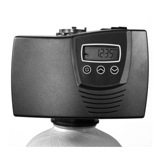
- Page 1 FLECK 7000SXT SERVICE MANUAL...
-
Page 2: Table Of Contents
TABLE OF CONTENTS IMPORTANT PLEASE READ: • The information, specifications and illustrations in this JOB SPECIFICATION SHEET ..........3 manual are based on the latest information available at INSTALLATION ..............4 the time of printing. The manufacturer reserves the right START-UP INSTRUCTIONS ..........5 to make changes at any time without notice. -
Page 3: Job Specification Sheet
JOB SPECIFICATION SHEET NOTE: Some options may not be available depending on valve model or other options chosen. Job Number: _____________________________________________________ Model Number: ___________________________________________________ Water Hardness:_________________________________________ppm or gpg Capacity Per Unit: _________________________________________________ Mineral Tank Size: ________________________________________________ Diameter: _______________________________________________________ Height: __________________________________________________________ Salt Setting per Regeneration: _______________________________________ 1. -
Page 4: Installation
INSTALLATION 10. On units with a by-pass, place in by-pass position. Turn on the main water supply. Open a cold soft water tap nearby and let run a few minutes or until the system is free from Water Pressure foreign material (usually solder) that may have resulted A minimum of 20 pounds (1.4 bar) of water pressure is from the installation. -
Page 5: Start-Up Instructions
START-UP INSTRUCTIONS • Day-of-the-Week controls. • While in service, the display alternates between time of The water softener should be installed with the inlet, day, volume remaining or days to regeneration, and tank outlet, and drain connections made in accordance with the in service (twin tank systems only). -
Page 6: Timer Operation
TIMER OPERATION Manually Initiating a Regeneration 1. When timer is in service, press the Extra Cycle button for 5 Meter Immediate Control seconds on the main screen. A meter immediate control measures water usage and 2. The timer advances to Regeneration Cycle Step #1 (rapid regenerates the system as soon as the calculated system rinse), and begins programmed time count down. -
Page 7: Master Programming Mode Chart
MASTER PROGRAMMING MODE CHART Before entering Master Programming, please CAUTION contact your local professional water dealer. Master Programming Options Abbreviation Parameter Option Options Abbreviation Gallons Display Format Liters dF2b Softener Double Backwash Fltr Filter Valve Type dFFF Downflow Fill First. Fixed/Variable Air Injected Oxidizer Meter Delayed Meter Immediate... -
Page 8: Master Programming Mode
MASTER PROGRAMMING MODE 2. Valve Type (Display Code VT) Press the Extra Cycle button. Use this display to set the Valve When the Master Programming Mode is entered, all available Type. The Valve Type setting specifies the type of cycle that the option setting displays may be viewed and set as needed. - Page 9 MASTER PROGRAMMING MODE 8. Safety Factor (Display Code SF) Press the Extra Cycle button. Use this display to set the Safety CONTINUED Factor. This setting specifies what percentage of the system capacity will be held as a reserve. Since this value is expressed 5.
- Page 10 MASTER PROGRAMMING MODE 15. Current Day (Display Code CD) Press the Extra Cycle button. Use this display to set the CONTINUED current day on systems that have been configured as Day of Week controls. This setting is identified by “CD” in the upper 12.Regeneration Time left-hand corner of the screen.
-
Page 11: User Programming Mode
USER PROGRAMMING MODE 6. Press the Extra Cycle button. Use this display to set the Current Day of the Week. This option setting is identified by “CD” in the upper left hand corner of the screen. User Programming Mode Options Abbreviation Parameter Description... -
Page 12: Diagnostic Programming Mode
DIAGNOSTIC PROGRAMMING MODE 6. Press the Up button. Use this display to view the Reserve Capacity. This option setting is identified by “RC” in the upper left hand corner of the screen. Diagnostic Programming Mode Options Abbreviation Parameter Description Flow Rate Displays the current outlet flow rate Peak Flow Displays the highest flow... -
Page 13: Powerhead Assembly
POWERHEAD ASSEMBLY BR61501-7000SXT Item No. Part No. Description Item No. Part No. Description 1 ....1 ..10218 ....Switch, Micro (Optional) 14 ....1 ..40981 ....Transformer, US 24V, 9.6 VA 2 ....1 ..40978 ....Support, Upper Bearing 14 ....1 ..41086 ....Transformer, European, 3 ....1 .. -
Page 14: Valve Assembly
VALVE ASSEMBLY * See NOTE NOTE: Installers are responsible for securing the plastic H Clips (p/n 40576 red clips) when attaching connectors. The red clips will break if you attempt to force into position without fully inserting the connector into the body. If the connector is inserted properly the red clip insertion path will be clear. -
Page 15: Bypass Assembly
BYPASS ASSEMBLY 41118 Rev A 41147 Rev A IMPORTANT: To bypass the valve, turn bypass knob on both sides of the valve to bypass position. When returning to service, put the inlet into service before the outlet. Item No. Part No. Description Item No. -
Page 16: Safety Brine Valve
SAFETY BRINE VALVE Item No. Part No. Description 1 ....1 ..19645 ....Body, Safety Brine Valve, 2310 2 ....1 ..19803 ....Safety Brine Valve Assy 3 ....1 ..19804 ....Screw, Sckt Hd, Set, 10-24 x 4 ....1 ..19805 ....Nut, Hex, 10-24, Nylon Black 5 ....1 .. -
Page 17: Troubleshooting
TROUBLESHOOTING Problem Cause Correction Water conditioner fails to Electrical service to unit has been interrupted Assure permanent electrical service (check fuse, plug, regenerate. pull chain, or switch) Timer is defective. Replace timer. Power failure. Reset time of day. Hard water. By-pass valve is open. - Page 18 TROUBLESHOOTING CONTINUED Error Codes NOTE: Error codes appear on the In Service display. Error Code Error Type Cause Reset and Recovery Cam Sense The valve drive took longer than Unplug the unit and examine the powerhead. Verify that all cam switches are Error 6 minutes to advance to the next connected to the circuit board and functioning properly.
-
Page 19: Removing Gear Box Assembly
REMOVING GEAR BOX ASSEMBLY 40988 REV A 41033 REV B Figure 3 Figure 5 1. Unplug the power source. CONNECTING THE CIRCUIT BOARD 2. With 3/8" nut driver, turn the cycle cam counter-clockwise to the position shown in illustration above. After the circuit board is installed: 3. -
Page 20: Water Conditioner Flow Diagrams
WATER CONDITIONER FLOW DIAGRAMS Second Backwash Position In Service Position 40988 REV A 41121 REV A 40988 REV A 41121 REV A Backwash Position Rapid Rinse Position 40988 REV A 41121 REV A 40988 REV A 41121 REV A Brine Position Brine Tank Refill Position 40988 REV A 41121 REV A... -
Page 21: Injector Flow Data
INJECTOR FLOW DATA TR18755 REV B FLECK • 21 7000SXT Service Manual... -
Page 22: Meter Flow Data
METER FLOW DATA TR18753 Softener TR18688 Filter 41140-02 REV A DIMENSIONS 41023 REV C 22 • FLECK 7000SXT Service Manual... - Page 23 FLECK • 23 7000SXT Service Manual...
- Page 24 All Pentair trademarks and logos are owned by Pentair, Inc. or its affiliates. All other registered and unregistered trademarks and logos are the property of their respective owners. Because we are continuously improving our products and services, Pentair reserves the right to change specifications without prior notice.
Need help?
Do you have a question about the FLECK7000SXT and is the answer not in the manual?
Questions and answers
Have a Fleck 7000 Back wash drain does not completely shut off. I figure seal are worn. Which ones need replaced?
If the backwash drain on a Pentair Fleck 7000SXT does not completely shut off, the seals and piston assembly need to be replaced.
This answer is automatically generated