
Subscribe to Our Youtube Channel
Related Manuals for Moore Industries SPA TPRG


Summary of Contents for Moore Industries SPA TPRG
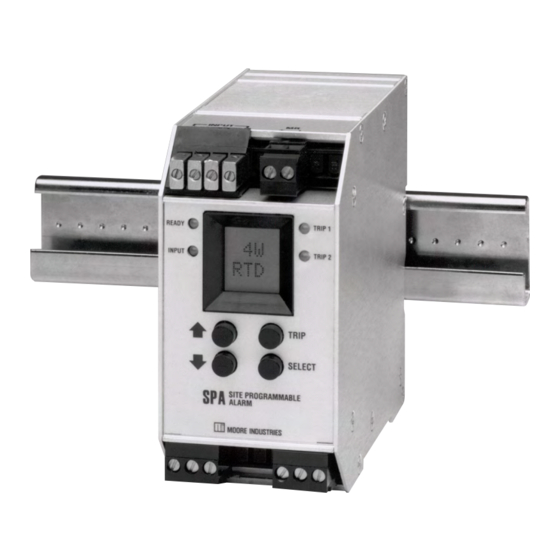
- Page 1 April 2016 Site-Programmable RTD & 224-721-00D Thermocouple Limit Alarm Trips TPRG The Interface Solution Experts...
- Page 2 SPA TPRG Quickstart Guide Use the front push-buttons to quickly and easily setup the SPA for your application. After programming your alarm using the diagram below, install the unit into your ap- plication using the connection diagram and terminal designation table on pages 28 and 29 of this manual.
-
Page 3: Table Of Contents
Table of Contents SPA TPRG Temperature Inputs ................. 4 Programmable Inputs ......................4 Programmable Outputs ......................4 Programmable Display ......................4 Programmable Input Failure Alarms ..................4 Total Sensor Diagnostics ......................4 Universal Mounting ......................4 Specifications ....................5 Alarm Terminology .................... 7 Internal Settings .................... -
Page 4: Spa Tprg Temperature Inputs
LED corresponding to the input changes color to flag Programmable Outputs the problem, and the LCD displays a message telling The SPA TPRG can be equipped with an analog exactly where the failure has occurred. output option to provide either a 1-5V or 4-20mA... -
Page 5: Specifications
Site-Programmable RTD & Thermocouple Limit Alarm Trips Specifications Performance Input Failure (Burn- Performance Repeatability: Trip point Ambient Ambient Temperature Ef- (continued) out) Protection: On repeats within ±0.05% of Conditions fect: ±0.005% of detected input failure, all output span per °C max.; input span (continued) relays switch to alarm state... - Page 6 Site-Programmable RTD & Thermocouple Limit Alarm Trips Table 1. SPA Input Accuracy Input Type Ω α Range Accuracy Minimum Span Selection -185°C to +540°C 1000 Pt RTD 3750 ±0.1°C (-301°F to +1004°F) 100, 200, 300, 100Ω: ±0.2°C; 200, 300, -200°C to +850°C 3850 400, 500, 1000 &...
-
Page 7: Alarm Terminology
Before setting up the SPA, or incorporating the unit in cally going from alarm to non-alarm. The reset point your application, Moore Industries suggests that all us- is not necessarily the same as the trip point, because ers take a few moments to become familiar with some most applications call for a buffer zone or “Deadband”... -
Page 8: Internal Settings
Site-Programmable RTD & Thermocouple Limit Alarm Trips Internal Settings The SPA housing is fitted with a sliding access door in its bottom panel. Figures 2, 3, and 4 show the panel The Failsafe/Non-failsafe relay and the password and the location of each of the controls for setting: security functions of the SPA are controlled by means of simple DIP switches and a single jumper inside the •... - Page 9 Site-Programmable RTD & Thermocouple Limit Alarm Trips Figure 3. Setting the Internal DIP Switches for Failsafe or Non-Failsafe Alarm Function FRONT BACK SPA UNDERSIDE SET FAILSAFE/NON-FAILSAFE FAILSAFE NON-FAILSAFE EXAMPLE: ALARMS 1 & 2 = NON-FAILSAFE ALARMS 3 & 4 = FAILSAFE NOTE: THIS 4-POSITION SIP SWITCH MAY VARY IN LOCATION BASED ON THE TYPE OF SPA USED Figure 4.
-
Page 10: Programming The Tprg Spa
Site-Programmable RTD & Thermocouple Limit Alarm Trips Programming the TPRG SPA Main Menu/View Settings Figure 5 gives an overview of the first level of menus The Temperature Input SPA operating parameters used to configure the TPRG SPA. are set, and the settings stored in on-board, non- volatile EEPROM. - Page 11 Site-Programmable RTD & Thermocouple Limit Alarm Trips Figure 5. The TPRG SPA Main Menu and Password Menu (Temperature, mV, or Ω Inputs) 000.0 DEG C DISPLAY OF PROCESS VALUE VIEW CONF EXIT VIEW SETTINGS MODE VIEW CONF CHOOSE INPUT SELECT SENS SELECT SENSOR TYPE...
-
Page 12: Password
Site-Programmable RTD & Thermocouple Limit Alarm Trips Figure 6. The TPRG SPA View Settings Mode Password This menu is bypassed if the Password Security Jumper is not installed (see Figure 2). If the jumper 000.0 DEG C is installed, the menu comes up when SELECT is pressed from the display of the process variable input. -
Page 13: Configure Sensor
Site-Programmable RTD & Thermocouple Limit Alarm Trips Configure Sensor Use the arrow buttons to toggle the display, turning RJC ON or OFF, and press In the TPRG, if the security jumper is not installed SELECT. (see Figure 2), the password sub-menu is bypassed, and the Configure Sensor menu is accessed when 5. - Page 14 Site-Programmable RTD & Thermocouple Limit Alarm Trips Figure 7. The TPRG SPA Configure Sensor Menu USE UP/DOWN BUTTONS CONF EXIT TO SCROLL THROUGH AVAILABLE SENSOR TYPES VIEW FROM THE CONF VIEW SENS MAIN MENU: SENS SELECT TYPE SELECT CONF OPTS WHAT TYPE OF SENSOR WAS...
-
Page 15: Configure Options
Site-Programmable RTD & Thermocouple Limit Alarm Trips Configure Options “SET FAIL” and the SF3 and AO/AOZ options This menu is for selecting display of °C or °F, The selection made in “SET FAIL” determines how the linearization on or off, and how the TPRG SPA SPA functions in the event of a sensor failure. - Page 16 Site-Programmable RTD & Thermocouple Limit Alarm Trips Figure 8. The TPRG SPA Configure Options Menu CONF OPTS CONF SENS VIEW SELECT CONF ALRM TOGGLE BETWEEN ENGU ˚C AND ˚F OPTS VIEW VIEW EXIT ˚C/˚F SELECT SELECT TOGGLE LINEARIZATION ON OR OFF VIEW VIEW BUTTONS...
-
Page 17: Configure Alarm(S)
Site-Programmable RTD & Thermocouple Limit Alarm Trips ENTER TRIP Configure Alarm(s) This menu sets: If the value of the trip point is known, use the Smart Ranging feature of the SPA to • Trip point(s) program the value into SPA memory. If the trip point is unknown, skip to step 7, •... - Page 18 Site-Programmable RTD & Thermocouple Limit Alarm Trips Figure 9. The TPRG SPA Configure Alarms Menu START ENTER CONF ENTR ALRM DEADBAND CONF OPTS VIEW VIEW XXXX DISPLAYS SELECT SELECT PASS DEGX ENGINEERING UNITS WORD VIEW USE ARROW BUTTONS AL 1 TO SET DISPLAY TO DESIRED DEADBAND CONF...
- Page 19 Site-Programmable RTD & Thermocouple Limit Alarm Trips Figure 10. Setting Up for “Capturing” Alarm Trip Points ENTER DEADBAND (Standard Ranging) 15. From the “ENTR DB” screen, press SELECT. MILLIVOLT SOURCE 16. Use the arrow buttons to change the OR T/C SIMULATOR deadband around the trip point in SPA memory.
- Page 20 Site-Programmable RTD & Thermocouple Limit Alarm Trips SET HI/LO SET LATCHING/NON-LATCHING 23. From the “SET HILO” screen, press 27. From the “SET LAT” screen, press SELECT. SELECT. 24. Use the arrow buttons to toggle the alarm 28. Use the arrow buttons to toggle the function between high alarm operation alarm function between latching (alarm (trips when input exceeds the trip point...
-
Page 21: Change The Security Password Code
Site-Programmable RTD & Thermocouple Limit Alarm Trips Figure 11. Changing the TPRG SPA Password Change the Security Password Code This menu is active when the Security Jumper is NOT PASS installed, or when the jumper is installed and a cor- WORD CONF rect password has been entered. -
Page 22: Configure Zero And Full Scale - Smart Ranging
Site-Programmable RTD & Thermocouple Limit Alarm Trips Configure Zero and Full Scale — Figure 12. Smart Ranging the AO/AOZ-equipped TPRG SPA Smart Ranging START This set of menus is available only on those units CONF equipped with one of the AO (Analog Output) options. Z/FS PASS Referred to as “Smart Ranging”, it allows the user to... -
Page 23: Input Zero And Full Scale - Bench Ranging
Site-Programmable RTD & Thermocouple Limit Alarm Trips Figure 13. Bench Ranging the AO/AOZ-equipped TPRG SPA Input Zero and Full Scale — Bench Ranging This set of menus is available only on those units equipped with one of the AO options. Referred to as START “Standard Ranging”, it allows the user to enter the val- Z/FS... -
Page 24: Trim Output
Site-Programmable RTD & Thermocouple Limit Alarm Trips Trim Output This procedure is only required on those SPAs 4. Press SELECT to begin the trim process. equipped with one of the available AO options. The display will begin to flash the “TRIM ZERO”... - Page 25 Site-Programmable RTD & Thermocouple Limit Alarm Trips Figure 14. Setting Up for Trimming the TPRG SPA Output Figure 15. Trimming the TPRG SPA Analog Output (AO/AOZ-equipped units only) (AO/AOZ-equipped units ONLY) START TRIM MILLIVOLT MULTIMETER SOURCE Z/FS OR T/C VIEW SIMULATOR SELECT CONF...
-
Page 26: Installation
Site-Programmable RTD & Thermocouple Limit Alarm Trips Installation Mounting To mount the SPA on Top Hat DIN-rail, seat the upper The SPA is housed in a universal DIN-style case. Its extrusion on the unit back panel over the top lip of the back panel is equipped with fittings that make it pos- rail and pivot downward until the housing locks into sible to mount the unit one both G-type and Top Hat... - Page 27 Please follow the external relay manufacturer instructions • Any Moore Industries product in a metal case or for their recommended relay coil suppression kits. Inductive housing should be grounded. loads should have suppression devices installed on the relay right across the relay coil itself.
-
Page 28: Connections
Site-Programmable RTD & Thermocouple Limit Alarm Trips Connections Configuration data, stored in memory, is monitored continuously. Changes can be made at any time. Any Figure 17 shows how to hook up the various inputs ac- changes made to operating parameters controlled by commodated by the TPRG SPA. - Page 29 Site-Programmable RTD & Thermocouple Limit Alarm Trips Table 3. Terminals for the SPA Top Row Terminals +Analog –Analog Low Level SPA – Present (Note 1) (Note 1) (Note 2) (Note 2) (Note 3) (Note 3) Middle Row Terminals 1 and 2 Relays Not Present (1PRG and 2PRG) Not Present...
-
Page 30: Leds
Site-Programmable RTD & Thermocouple Limit Alarm Trips NOTE: LEDs The state of the SPA relays in alarm or non- There are at least three, and as many as six LEDs alarm is determined by the failsafe/non-failsafe on the front panel of the SPA. Each is labeled, and setting of the unit’s internal DIP switches provides a quick reference for input condition during (see Figure 3, earlier in this manual). -
Page 31: Error Codes
Moore Industries STAR Center customer service department. As a safeguard, the unit is equipped with a full set of... - Page 32 4. Ship the equipment to the Moore Industries location nearest you. The returned equipment will be inspected and tested at the factory. A Moore Industries rep- resentative will contact the person designated on your documentation if more information is needed.
Need help?
Do you have a question about the SPA TPRG and is the answer not in the manual?
Questions and answers