
Related Manuals for Moore Industries STA HLPRG


Summary of Contents for Moore Industries STA HLPRG
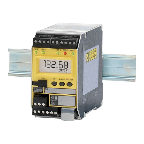
- Page 1 Demand Moore Reliability HLPRG User’s Manual Programmable Current/Voltage 225-748-01L Safety Trip Alarm February 2017 www.miinet.com...
- Page 2 We perform a sequence of stringent quality assurance checks on every unit we ship. If any Moore Industries product fails to perform up to rated specifications, call us for help. Our highly skilled staff of trained technicians and engineers pride themselves on their ability to provide timely, accurate, and practical answers to your process instrumentation questions.
- Page 3 All Moore Industries instrumentation should only be used for the purpose and in the manner described in this manual. If you use this product in a manner other than that for which it was intended, unpredictable behavior could ensue with possible hazardous consequences.
-
Page 4: Table Of Contents
High Availability Architecture ........................69 1oo2 Redundant Architecture ........................70 Analog Output in the Safety Path ......................... 71 High Integrity Analog Output ........................71 Section 9 - Specifications Section 10- Ordering Information Warranty Disclaimer www.miinet.com - 4 - Moore Industries-International, Inc. -
Page 5: Sta (Hlprg) Quick Start Guide
The STA configuration can be recorded using the worksheet found at the end of this manual. Please contact Moore Industries Sales for an interactive version of the worksheet. Use the UP and DOWN pushbuttons to scroll through menus and... -
Page 6: Default/Factory Configuration
Display: Process Variable (PV), Auto Decimal Point, 60Hz Filter Broken Wire Detection: Level Set to 0 (disabled) Password: 1 * For STA units with firmware versions 1.5 and earlier, these Settings are not configurable. www.miinet.com - 6 - Moore Industries-International, Inc. -
Page 7: Section 1 - Introduction
This is the user’s manual for Moore Industries’ STA (HLPRG): Programmable Current/Voltage Safety Trip Alarm. The Moore Industries’ Safety Trip Alarm (STA) is designed and manufactured to provide a high level of availability for safety critical applications and for use as a component part of a safety instrumented system. -
Page 8: Model Numbers And Options
Programmable Current/Voltage Safety Trip Alarm February 2017 Model Numbers and Options The following section provides details of the Moore Industries model number and the available options for the STA. Moore Industries model numbers for STA are structured as follows: STA / HLPRG / 3PRG / U / -AO [DIN]... - Page 9 Note: For units with firmware V1.2 or earlier, the Analog Output cannot be used as part of the safety path. HOUSING [DIN] DIN-style housing mounts on a 35mm Top Hat rail (EN50022) [FLB] Flange bracket provides a secure mount for high vibration applications. Moore Industries-International, Inc. www.miinet.com - 9 -...
-
Page 10: Alarm Terminology
February 2017 Alarm Terminology Before setting up the STA, or incorporating the unit in your application, Moore Industries suggests that all users take a few moments to become familiar with some of the terms associated with the use of process instrumentation alarms. - Page 11 Open or Normally Closed, with a non-alarm input condition. In this manual, “normal” is an exclusive reference to the shelf state or quiescent state of an alarm’s relay contacts, whether open or closed. Moore Industries-International, Inc. www.miinet.com - 11 -...
-
Page 12: Section 2 - Calibration And Bench Check
It is recommended that you perform a bench check on your instruments prior to installing them in your application. Calibration A true calibration of the STA can only be performed at Moore Industries using specialized equipment. We recommend that you check the calibration every year and re-calibrate only when necessary. - Page 13 1. Current or Voltage Input: In order to provide an input to your STA HLPRG you will need to use an appropriate input source. By example – if you plan to use your STA with a current (mA) input you will need to use a milliamp source to provide the appropriate input during your bench check.
- Page 14 By example – a 5V reading across your 250 ohm resistor equates to a 20mA output. You have now confirmed that your STA is operating correctly and can now be confidently installed into your application. www.miinet.com - 14 - Moore Industries-International, Inc. Moore industries-International, Inc.
-
Page 15: Section 3 - Installation And Wiring
STAs. Note: Any changes to Security Settings will need to be made prior to installation and wiring refer the Security Settings Section in this section. Dimensions Figure 3.1. Dimensions of STA HLPRG 56mm (2.2 in) 17.29 102mm (4.0 in) -
Page 16: Conditions Of Use
Electronic components must be mounted in a suitable enclosure. Figure 3.2. FLB flange bracket dimensions. 18mm 23mm (0.7 in) (0.9 in) (0.4 in) 2 mm (0.1 in) 11mm (0.4 in) 143mm (5.6 in) 121mm (4.8in) Ø6mm (Ø0.3 in) www.miinet.com - 16 - Moore Industries-International, Inc. -
Page 17: Terminal Designations
Electrical Connections Refer to Figure 3.4 for electrical connections. When installing any Moore Industries product, always follow all local regulations and standards for grounding, shielding, and safety. Warning: Terminals on this unit may be connected to hazardous voltages. Before making ANY connections to this unit, always remove power from the loop or instrument power terminals. - Page 18 AC OR DC AC OR DC POWER POWER SUPPLY SUPPLY 2-WIRE TRANSMITTER ( Output Loop Powered Device) READY INPUT TRIP 1 TRIP 2 FAULT DOWN SELECT SAFETY TRIP ALARM AC OR DC POWER SUPPLY www.miinet.com - 18 - Moore Industries-International, Inc.
- Page 19 (1-5V) input and a 4-20mA output. Products connected to the STA should be designed to receive this type of input. Warning: If this unit is used in a manner not specified by Moore Industries, the protection provided by the equipment may be impaired.
- Page 20 CE Certification-related Guidelines Installation of any Moore Industries’ products that carry the CE marking must adhere to the guidelines in the Recommended Ground Wiring Practices section in order to meet the EN 61326 requirements set forth in the applicable EMC directive.
-
Page 21: Security Settings
View Menu. Note: These security settings are only applicable to access via the front panel pushbuttons. Security can be bypassed using the PC Configuration Software. See PC Configuration Software section for more information. Moore Industries-International, Inc. www.miinet.com - 21 -... -
Page 22: Section 4 - Sta Front Panel Configuration
Reset Fault menu, MR (if configured) or by power cycling the unit. Note: For STA units with firmware versions 1.5 and earlier, the input fault alarm has no configuration options, it is always latched and cannot be reset by Manual Reset (MR). www.miinet.com - 22 - Moore Industries-International, Inc. - Page 23 MAIN Menu (Enter Pass) MENU (Display of Variable) Display of MAIN Menu other var XXXXX MAIN Menu ZERO XXXXX MAIN Menu FULL XXXXX MAIN Menu AL1 X* XXXXX MAIN Menu (Enter Pass) AL2 X* Moore Industries-International, Inc. www.miinet.com - 23 -...
- Page 24 (default value is “1”). When the password is displayed, press SELECT. Note: If the correct password is not known, contact Moore Industries Technical Support for assistance, or use the PC Configuration Software to bypass security. If you have entered the correct password, the sensor configuration menu, “CONFG INPUT”, will be accessed.
- Page 25 CONFG AOUT AOUT menu SCALE SCALE AOUT AOUT menu TRIM TRIM AOUT AOUT menu CONFG CONFG OPTNS OPTNS menu CONFG CONFG PASWD PASWD menu RESET RESET FAULT FAULT CONFG CONFG EXIT EXIT menu Moore Industries-International, Inc. www.miinet.com - 25 -...
- Page 26 The next display is the “SCALE INPUT” menu. To skip the rest of the configuration menus and return to the process variable display, press the UP or DOWN button until you reach “CONFG EXIT”, and press SELECT. Refer to “CONFG EXIT” section of this manual for more information. www.miinet.com - 26 - Moore Industries-International, Inc.
- Page 27 Value Change: ZERO XX.XX Sensor EGU INPUT INPUT Value FULL Value Change: Change: ZERO XX.XX XX.XX INPUT FULL Value Change: INPUT XX.XX EXIT BWIRE LEVEL Value Change: XX.XX EXIT INPUT SCALE INPUT menu Moore Industries-International, Inc. www.miinet.com - 27 -...
- Page 28 This value will appear when you are at the full end of your range. Press SELECT. “EXIT SCALE” appears. If all scaling parameters have been set, press SELECT. The next menu selection to appear is “TRIM INPUT”. www.miinet.com - 28 - Moore Industries-International, Inc.
- Page 29 Figure 4.4. SCALE INPUT Menu SCALE INPUT Selection: SCALE SCALE OFF MODE SCALE ON SCALE Set Chars: X---- SCALE Value Change: ZERO XX.XX SCALED ZERO SCALE Value Change: FULL XX.XX SCALED FULL EXIT SCALE TRIM INPUT menu Moore Industries-International, Inc. www.miinet.com - 29 -...
- Page 30 ERROR TRIM will be displayed after values are applied. Press SELECT to exit ERROR TRIM, which will prompt EXIT TRIM. Use the UP or DOWN buttons to return to TRIM ZERO and/or TRIM FULL to make changes needed. www.miinet.com - 30 - Moore Industries-International, Inc.
- Page 31 RESET YES TRIM Change Value: Capture Value: ZERO XX.XX XX.XX APPLY (Flashing) ERROR TRIM TRIM Change Value: Capture Value: FULL XX.XX XX.XX APPLY (Flashing) ERROR FCTRY TRIM TRIM EXIT TRIM CONFG ALARM menu Moore Industries-International, Inc. www.miinet.com - 31 -...
- Page 32 At the “INPUT FAULT” display, press SELECT, this will display “LATCH YES?” to set latch press SELECT or press DOWN button to display “LATCH NO?”, press SELECT here if you want to disable latching. www.miinet.com - 32 - Moore Industries-International, Inc.
- Page 33 LATCH HI/LO ALARM HI YES? ALARM LO INPUT LATCH FAULT LATCH Selection: LATCH ON LATCH OFF TRIP ONLY MANL ENTER RESET DELAY Value Change: TRIP+ IPFLT EXIT EXIT ALRMx ALARM CONFG AOUT menu Moore Industries-International, Inc. www.miinet.com - 33 -...
- Page 34 HOLD LAST– This will cause the analog output to maintain the last valid value present before the failure. Note: The AO must be set to fail low if used in a safety system - please refer to section 7 for more information www.miinet.com - 34 - Moore Industries-International, Inc.
- Page 35 Programmable Current/Voltage Safety Trip Alarm February 2017 Figure 4.7. CONFG AOUT Menu CONFG AOUT Selection: VOLT AOUT CURNT Value Change: DAMP Selection: FAIL FAIL HIGH MODE FAIL LOW HOLD LAST EXIT AOUT SCALE AOUT menu Moore Industries-International, Inc. www.miinet.com - 35 -...
- Page 36 In either case there needs to be a minimum Span of 4mA or 1V. Figure 4.8. SCALE AOUT Menu SCALE AOUT Value Change: AOUT XX.XX ZERO MA/VOLT AOUT Value Change: FULL XX.XX MA/VOLT EXIT SCALE TRIM AOUT menu www.miinet.com - 36 - Moore Industries-International, Inc.
- Page 37 To enable the analog output test, press SELECT at the “TEST AOUT” display. Use the UP and DOWN buttons to set your output test value and press SELECT. “EXIT TRIM” appears; press SELECT. Moore Industries-International, Inc. www.miinet.com - 37 -...
- Page 38 Figure 4.9. TRIM AOUT Menu TRIM AOUT Value Change: TRIM XX.XX ZERO MA/VOLT Value Change: TRIM XX.XX FULL MA/VOLT FCTRY Selection: TRIM RESET NO RESET YES TEST Value Change: AOUT XX.XX MA/VOLT EXIT TRIM CONFG OPTNS menu www.miinet.com - 38 - Moore Industries-International, Inc.
- Page 39 TRIP 1 TRIP 2 FAULT SELECT DOWN SAFETY TRIP ALARM AC OR DC POWER SUPPLY HOOK-UPS FOR OUTPUT TRIMMING EXTERNAL POWER SUPPLY MULTIMETER MULTIMETER MULTIMETER CURRENT OUTPUT SOURCE CURRENT OUTPUT SINK VOLTAGE OUTPUT Moore Industries-International, Inc. www.miinet.com - 39 -...
- Page 40 “RESET NO?” and “RESET YES?”; press SELECT. Note: When resetting unit to factory default, refer to the Quick Set-Up Guide on Pg. 5 for default values. “EXIT OPTNS” appears. Press SELECT. Proceed to the “CONFG PASWD” menu. www.miinet.com - 40 - Moore Industries-International, Inc.
- Page 41 FILTR 50 HZ 60 HZ START DELAY Change Value: XXX SEC DSPLY TEST Display test is executed, returns to FCTRY CONFG. FCTRY Selection: CONFG RESET NO RESET YES EXIT OPTNS CONFG PASWD menu Moore Industries-International, Inc. www.miinet.com - 41 -...
- Page 42 Note: If the security is set to Full Access a password can be set but will not be requested to use and configure STA unit. Please refer to Security Settings in Section 3. Figure 4.12. CONFG PASWD Menu CONFG PASWD Value Change: CONFG XXXX PASWD PASS EXIT PASWD RESET FAULT menu www.miinet.com - 42 - Moore Industries-International, Inc.
- Page 43 Customer Service for further assistance. Refer to Table 6.1 for a full list of STA diagnostic messages and corrective actions. Figure 4.13. RESET FAULT RESET FAULT Selection: RESET YES? CONFG EXIT RESET NO? Moore Industries-International, Inc. www.miinet.com - 43 -...
- Page 44 If “ERROR UNDO” is selected, you will be returned to View menu and no changes will be applied to unit (previous configuration will remain unchanged). Figure 4.14. CONFG EXIT Menu CONFG EXIT ENTER VIEW PASS MENU Selection: SEL (error) ERROR LIST? SEL UNDO ERROR UNDO? ENTER CONFG INPUT www.miinet.com - 44 - Moore Industries-International, Inc.
-
Page 45: Section 5 - Sta Pc Configuration
Installing the Configuration Software Refer to Table 5.1 for the equipment needed. Check the Moore Industries website @ www.miinet.com for the latest software package to ensure you have the latest release. Also if you are not able to go online install software using the included Moore Industries Interface Solution PC Configuration Software CD. - Page 46 PC hard drive or disk. The STA communicates with the PC through an RS-232 connection or USB Communications Cable. Note: Refer to the STA HLPRG Quick-Start Guide to see the default factory settings for your unit. Caution: Unplugging the programming cable or resetting power while downloading to the unit could result in a default configuration / calibration and the unit may have to be returned to the factory.
- Page 47 No Device (grey light). 3. Program Status– This portion of the program displays the activity of the connected unit. It will display such messages as: Reading STA Info, Idle, Monitoring Variables and Monitor Fail. Moore Industries-International, Inc. www.miinet.com - 47 -...
- Page 48 -AO option) is performed here. Refer to the Analog Output section for a complete description. 14. Summary Tab– Displays the Data Source, Model and all Configuration parameters for Input Type, Trimming, Scaling, Display Settings, Alarm Settings, and Analog Output Settings in a summarized format. www.miinet.com - 48 - Moore Industries-International, Inc.
- Page 49 This includes the PV and AO (only applicable if unit has AO). In order to stop Monitoring Mode, click on the icon or click Stop in the Monitoring Menu. This will stop monitoring. Moore Industries-International, Inc. www.miinet.com - 49 -...
- Page 50 Also, when attempting to download, or upload, monitoring must be stopped. To do this, click “Stop” in the Monitoring dropdown menu, or click the “Stop Monitoring” icon. www.miinet.com - 50 - Moore Industries-International, Inc.
- Page 51 Input Zero. Note: Broken Wire Detection “BWIRE” can only be set if the Lower Range Value (LRV) is set higher than zero (refer to the “INPUT ZERO” step 4). Moore Industries-International, Inc. www.miinet.com - 51 -...
- Page 52 0 secs. Note: Once you have configured all parameters, download to the unit by selecting “Download” in the Transfer dropdown menu located in the Status Bar. Or, click the button in the Menu Bar. www.miinet.com - 52 - Moore Industries-International, Inc.
- Page 53 “X”. Note: Once you have configured all parameters, download to the unit by selecting “Download” in the Transfer dropdown menu located in the Status Bar. Or, click the button in the Menu Bar. Moore Industries-International, Inc. www.miinet.com - 53 -...
- Page 54 Precision– Select the number of decimal places/resolution of your display (default is Auto). Note: Once you have configured all parameters, download to the unit by selecting “Download” in the Transfer dropdown menu located in the Status Bar. Or, click the button in the Menu Bar. www.miinet.com - 54 - Moore Industries-International, Inc.
- Page 55 60, the delay will not operate correctly. (The firmware revision of the unit is displayed at power up and in the STA Device Info window of the PC Configuration software). Moore Industries-International, Inc. www.miinet.com - 55 -...
- Page 56 Reset is engaged. Note: Once you have configured all parameters, download to the unit by selecting “Download” in the Transfer dropdown menu located in the Menu Bar. Or, click the button in the Menu Bar. www.miinet.com - 56 - Moore Industries-International, Inc.
- Page 57 Note: Once you have configured all parameters, download to the unit by selecting “Download” in the Transfer dropdown menu located in the Status Bar. Or, click the button in the Menu Bar. Moore Industries-International, Inc. www.miinet.com - 57 -...
- Page 58 “STA Status” display reading “**Output fixed**”. Clicking the “Unfix” button will clear this message. Changes made to the Output Test section will immediately affect the unit. Output test is disabled when there is no unit connected. www.miinet.com - 58 - Moore Industries-International, Inc.
- Page 59 Note: When user uploads a configuration from unit and then alters the displayed configuration a [modified] tag will be displayed before the Device Tag in Summary Tab. Once you download configuration to unit the [modified] tag will disappear. Moore Industries-International, Inc. www.miinet.com - 59 -...
-
Page 60: Section 6 - Operation And Maintenance
Before saving a new configuration to the unit, it will be checked for validity. If it is invalid, the fault alarm will be set. Once the configuration is corrected, the fault alarm will be cleared. www.miinet.com - 60 - Moore Industries-International, Inc. -
Page 61: Sta Diagnostic Messages
Identical diagnostics are performed in the background during run time. If a fault is detected, the fault alarm will immediately be set, and an error message will be displayed. Table 6.1 provides a full list of diagnostic messages and corrective actions. Moore Industries-International, Inc. www.miinet.com - 61 -... -
Page 62: Maintenance
Note: The Manual Reset (MR) will only reset Input Faults if configured in the Alarms Menu. Maintenance Moore Industries recommends that the calibration of this instrument should be checked every year and re-calibrated only when necessary. In addition, we suggest a quick check for terminal tightness and general unit condition. -
Page 63: Section 7 - Sta In Safety Instrumented Systems
. For units with firmware V1.5 and later, the STA is certified to 61508:2010 by exida ® ® Failure Rate Data The STA FMEDA report (Moore Industries’ Document No: 700-702-32) provides the failure data (including PFD and SFF) required for calculations to use the STA as part of a Safety Instrumented System. Product life The product life of the STA is 20 years (based on worst case component life data). - Page 64 Sensor Types The STA is designed for use with a wide variety of inputs. It is the end user’s responsibility to ensure that the chosen sensor is capable of achieving the required loop SIL. www.miinet.com - 64 - Moore Industries-International, Inc.
- Page 65 The STA has a characteristic response time (end to end) of 256mSec. The total diagnostic test time of the unit is 15 minutes. Moore Industries-International, Inc. www.miinet.com - 65 -...
- Page 66 The STA is not intended to be repaired on site and has no components needing maintenance or regular replacement. On device failure, the STA should be returned to Moore Industries Worldwide Headquarters in North Hills, CA 91343 U.S.A for repair and refurbishment (refer to Returns Procedures at the end of this manual).
-
Page 67: Proof Tests
225-748-01L Programmable Current/Voltage Safety Trip Alarm February 2017 Proof Tests Table 7.1. STA HLPRG proof test steps Step Action Bypass the safety PLC or take other appropriate action to avoid a false trip Disconnect all wires from the STA. Using an ohmmeter, measure the resistance between the case and all exposed pins on the front. - Page 68 The tests outlined below provide coverage only for the AO portion of the STA. It is necessary to perform the proof tests in both Table 7.1 and Table 7.2 if the Analog output is part of the safety path. Table 7.2. STA HLPRG Analog Output proof test steps Step Action...
-
Page 69: Section 8 - Applications
Figure 8.2. High Availability Alarm Trip example READY INPUT TRIP 1 TRIP 2 FAULT Process 17.29 Trip 1 Final Element Process DOWN SELECT Trip 2 Fault SAFETY TRIP Logic Solver/ ALARM Alarm SIF Alarm Moore Industries-International, Inc. www.miinet.com www.miinet.com - 69 -... -
Page 70: 1Oo2 Redundant Architecture
Fault SAFETY Alarm TRIP ALARM Final Element/ Sensor Input 2 Logic Solver READY INPUT TRIP 1 TRIP 2 FAULT Process Trip 1 17.29 Process DOWN SELECT Trip 2 Fault SAFETY Alarm TRIP ALARM www.miinet.com - 70 - Moore Industries-International, Inc. -
Page 71: Analog Output In The Safety Path
STA safe failures will also drive the AO signal out of range. Figure 8.5. High Integrity Analog Output example READY INPUT TRIP 1 TRIP 2 FAULT Tx or I+ Analog Output 126.39 DEG C DOWN SELECT Fault Relay SAFETY TRIP ALARM Moore Industries-International, Inc. www.miinet.com www.miinet.com - 71 -... -
Page 72: Section 9 - Specifications
Analog Output Range: Current Output 0-21.6mA, Minimum Span 4mA; Voltage Weight 513 g to 564 g Output -0.2-10.5V; Minimum Span 1V (18.1 oz to 19.9 oz) * Power Supply options no longer available for purchase www.miinet.com - 72 - Moore Industries-International, Inc. - Page 73 Input to Relay (Years) Input to Analog Output (Years) Stability (% of maximum span) 3yrs 5yrs 3yrs 5yrs Current Inputs 0.081 0.14 0.18 0.047 0.081 0.105 Voltage Inputs 0.093 0.16 0.21 0.066 0.114 0.147 Moore Industries-International, Inc. www.miinet.com www.miinet.com - 73 -...
-
Page 74: Section 10- Ordering Information
HLPRG User’s Manual 225-748-01L Programmable Current/Voltage Safety Trip Alarm February 2017 Section 10- Ordering Information The STA HLPRG ordering information is detailed below. Unit Input Output Power Options Housing HLPRG 3PRG Dual Process -AO Analog output Programmable Programs to accept:... -
Page 75: Warranty Disclaimer
Return Policy For a period of thirty-six (36) months from the date of shipment, and under normal conditions of use and service, Moore Industries (“The Company”) will at its option replace, repair or refund the purchase price for any of its manufactured products found, upon return to the Company (transportation charges prepaid and otherwise in accordance with the return procedures established by The Company), to be defective in material or workmanship.
Need help?
Do you have a question about the STA HLPRG and is the answer not in the manual?
Questions and answers