Table of Contents
Advertisement
Available languages
Available languages
IMPORTANT:
Read Before Using
11224VSRC
Toll Free Number:
1-877-BOSCH99 (1-877-267-2499) http://www.boschtools.com
For English
See page 2
IMPORTANT :
Lire avant usage
Operating/Safety Instructions
Consignes de fonctionnement/sécurité
Instrucciones de funcionamiento
y seguridad
Consumer Information
Renseignement des consommateurs
Información para el consumidor
Appel gratuit :
Parlez-vous français?
Voir page 11
IMPORTANTE:
Leer antes de usar
Número de teléfono gratuito:
¿Habla español?
Ver página 20
Advertisement
Table of Contents

Subscribe to Our Youtube Channel
Related Manuals for Bosch 11224VSRC


Summary of Contents for Bosch 11224VSRC
- Page 1 IMPORTANT: Read Before Using Operating/Safety Instructions Consignes de fonctionnement/sécurité Instrucciones de funcionamiento y seguridad 11224VSRC Renseignement des consommateurs Toll Free Number: 1-877-BOSCH99 (1-877-267-2499) http://www.boschtools.com For English See page 2 IMPORTANT : Lire avant usage Consumer Information Información para el consumidor Appel gratuit : Parlez-vous français?
-
Page 2: Power Tool Safety Rules
Read and understand all instructions. Failure to follow all instructions WARNING listed below, may result in electric shock, fire and/or serious personal injury. Work Area Keep your work area clean and well lit. Cluttered benches and dark areas invite accidents. Do not operate power tools in explosive atmospheres, such as in the presence of flammable liquids, gases, or dust. -
Page 3: Tool Use And Care
job better and safer at the rate for which it is designed. Do not use tool if switch does not turn it “ON” or “OFF”. Any tool that cannot be controlled with the switch is dangerous and must be repaired. Disconnect the plug from the power source before making any adjustments, changing accessories, or storing the tool. - Page 4 Position yourself to avoid being caught between the tool or side handle and walls or posts. Should the bit become bound or jammed in the work, the reaction torque of the tool could crush your hand or leg. If the bit becomes bound in the workpiece, release the trigger immediately, reverse the direction of rotation and slowly squeeze the trigger to back out the bit.
-
Page 5: Symbols
MPORTANT: Some of the following symbols may be used on your tool. Please study them and learn their meaning. Proper interpretation of these symbols will allow you to operate the tool better and safer. Symbol Name Volts Amperes Hertz Watt Kilograms Minutes Seconds... -
Page 6: Functional Description And Specifications
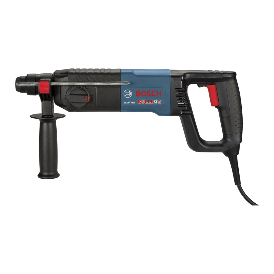
SHIELD DEPTH GAUGE Rotary Hammer FIG. 1 SELECTOR DIAL DEPTH GAUGE RELEASE BUTTON AUXILIARY HANDLE HAND GRIP Model number 11224VSRC Shank style SDS-plus Maximum Capacities: Carbide tipped bits 7/8" Thin wall core bits 2-1/2" TRIGGER SWITCH REVERSING SWITCH LEVER RELEASE BUTTON SELECTOR DIAL ®... -
Page 7: Operating Instructions
INSTALLING SDS-plus Clean the insert shank end of the accessory to remove any debris, then lightly grease with a light oil or lubricant Insert accessory into the tool holder through the dust shield, while twisting and pushing inward until it locks automatically into place. Pull outward on the accessory to be certain it is locked into the tool holder (Fig. -
Page 8: Selector Dial
INSTALLING ACCESSORIES 3-JAW CHUCK Hold chuck collar with one hand and rotate chuck sleeve in direction of arrow with the other hand until the jaws are open (Fig. 6). For small bits, open jaws enough to insert the bit up to the flutes. For large bits, insert the bit as far as it will go. - Page 9 SLIP CLUTCH The tool has a internal pre-set slip clutch. The output spindle will stop rotating if the accessory binds and overloads the tool. AUXILIARY HANDLE The tool must be supported with the auxiliary handle, which can be swiveled 360˚. To reposition and/or swivel the handle, loosen the hand grip, move the handle to the desired position along the barrel and...
-
Page 10: Tool Lubrication
Service Preventive maintenance WARNING performed by unauth- orized personnel may result in misplacing of internal wires and components which could cause serious recommend that all tool service be performed by a Bosch Factory Service Center or Autho- rized Bosch Service Station. TOOL LUBRICATION Your Bosch tool has been properly lubricated and is ready to use. -
Page 11: Règles De Sécurité Générales
Vous devez lire et comprendre toutes les instructions. Le non-respect, même AVERTISSEMENT partiel, des instructions ci-après entraîne un risque de choc életrique, d'incendie et/ou de blessures graves. Aire de travail Veillez à ce que l'aire de travail soit propre et bien éclairée. - Page 12 sécuritaire. Respectez aussi la vitesse de travail qui lui est propre. N'utilisez pas un outil si son interrupteur est bloqué. Un outil que vous ne pouvez pas commander par son interrupteur est dangereux et doit être réparé. Débranchez la fiche de l'outil avant d'effectuer un réglage, de changer d'accessoire oude ranger l'outil.
- Page 13 rotation et appuyez lentement sur la gâchette pour faire ressortir le foret. Soyez prêt à un fort couple de réaction. Le corps du marteau aura tendance à tordre en sens opposé à mesure que le foret tourne. (Remarque : N’utiliser que si l’outil possède une marche arrière.) Ne frappez pas le foret avec une masse ou un marteau à...
- Page 14 IMPORTANT : Certains des symboles suivants peuvent être utilisés sur votre outil. Veuillez les étudier et apprendre leur signification. Une interprétation appropriée de ces symboles vous permettra d'utiliser l'outil de façon plus efficace et plus sûre. Symbole Volts Ampères Hertz Watt Kilogrammes Minutes...
-
Page 15: Description Fonctionnelle Et Spécifications
BUTÉE DE PROFONDEUR POIGNÉE AUXILIAIRE POIGNÉE (PRISE) Numéro de modèle Type de tige Capacités maximales : Mèches à pointe au carbure Mèches creuses à paroi mince -15- INTERRUPTEUR À GÂCHETTE D’INTERRUPTEUR BOUTON DE DÉCLENCHEMENT 11224VSRC ® SDS-plus 24 mm 65 mm LEVIER... -
Page 16: Consignes De Fonctionnement
INSTALLATION D’ACCESSOIRES SDS-PLUS Nettoyez la tige de l’embout de l’accessoire pour en enlever toute saleté, puis enduisez-la modérément d’une huile ou graisse légère. Au pare-poussière, introduisez l’accessoire dans la douille de retenue tout en le tordant et l’enfonçant jusqu’à ce qu’il se verrouille automatiquement en place. Tirez sur l’embout pour vous assurer qu’il est bien engagé... - Page 17 INSTALLATION D’ACCESSOIRES MANDRIN À 3 MORS Tenez la bague du mandrin d’une main et de l’autre tournez le manchon du mandrin dans le sens de la flèche jusqu’à ce que les mors soient ouverts (Fig. 6). Pour les petits forets, ouvrez les mors juste assez pour enfoncer l’embout jusqu’aux cannelures.
- Page 18 ACCOUPLEMENT À GLISSEMENT L’outil renferme un accouplement à glissement préréglé. L’arbre arrêtera de tourner si l’accessoire grippe et surcharge l’outil. POIGNÉE AUXILIAIRE La poignée auxiliaire, qui pivote sur 360°, doit être utilisée pour supporter l’outil. Pour repositionner et/ou faire pivoter la poignée, desserrez la manette, déplacez la poignée à...
-
Page 19: Entretien
Service Tout entretien préventif AVERTISSEMENT effectué personnels non autorisés peut résulter en mauvais placement de fils internes ou de pièces, ce qui peut présenter un danger grave. Nous vous conseillons de faire faire tout l’entretien par un centre de service d’usine Bosch ou une station service agréée Bosch. -
Page 20: Area De Trabajo
Normas de seguridad para herramientas mecánicas Lea y entienda todas las instrucciones. El incumplimiento de todas las instrucciones ADVERTENCIA indicadas a continuación puede dar lugar a sacudidas eléctricas, incendios y/o lesiones personales graves. Area de trabajo Mantenga el área de trabajo limpia y bien iluminada. Las mesas desordenadas y las áreas oscuras invitan a que se produzcan accidentes. - Page 21 Utilización y cuidado de las herramientas Utilice abrazaderas u otro modo práctico de fijar y soportar la pieza de trabajo a una plataforma estable. La sujeción de la pieza de trabajo con la mano o contra el cuerpo resulta inestable y puede ocasionar pérdida de control.
- Page 22 que generan polvo. Las gafas de seguridad o la protección de los ojos ayudarán a desviar los fragmentos del material que puedan salir despedidos hacia la cara y los ojos. El polvo generado o los gases liberados por los materiales que esté cortando (por ej., tuberías con aislamiento de asbesto, radón) pueden causar dificultades respiratorias.
- Page 23 IMPORTANTE: Es posible que algunos de los símbolos siguientes se usen en su herramienta. Por favor, estúdielos y aprenda su significado. La interpretación adecuada de estos símbolos le permitirá utilizar la herramienta mejor y con más seguridad. Símbolo Nombre Volt Ampere Hertz Watt...
-
Page 24: Descripción Funcional Y Especificaciones
Brocas con punta de carburo Brocas para de pared delgada Martillo giratorio DIAL SELECTOR BOTÓN DE LIBERACION DEL CALIBRE DE PROFUNDIDAD MANGO AUXILIAR EMPUÑADURA -24- INTERRUPTOR GATILLO PALANCA DEL INTERRUPTOR DE INVERSION BOTÓN DE LIBERACIÓN 11224VSRC ® SDS-plus 7/8" 2-1/2... -
Page 25: Instrucciones De Funcionamiento
INSTALACIÓN DE ACCESORIOS SDS-PLUS Limpie el extremo de inserción del cuerpo del accesorio para quitar los residuos que éste pueda tener y luego engráselo ligeramente con un aceite o lubricante ligero. Introduzca el accesorio en el portaherramienta a través del protector antipolvo a la vez que lo hace girar y lo empuja hacia adentro hasta que quede fijo en su sitio automáticamente. - Page 26 INSTALACIÓN DE ACCESORIOS MANDRIL DE 3 MORDAZAS Sujete el collarín del mandril con una mano y gire el manguito del mandril en el sentido de la flecha con la otra mano hasta que las mordazas estén abiertas (Fig. 6). En el caso de brocas pequeñas, abra las mordazas lo suficiente como para poder introducir la broca hasta las estrías.
- Page 27 EMBRAGUE DESLIZANTE Esta herramienta está dotada con un embrague deslizante interno preajustado. El husillo de salida dejará de girar si el accesorio se atasca y sobrecarga la herramienta. MANGO AUXILIAR La herramienta se debe sujetar con el mango auxiliar, el cual se puede girar 360°.
-
Page 28: Mantenimiento
Servicio El mantenimiento preventivo ADVERTENCIA realizado por personal no autorizado pude dar lugar a la colocación incorrecta de cables y componentes internos que podría constituir un peligro serio. Recomendamos que todo el servicio de las herramientas sea realizado por un Centro de servicio de fábrica Bosch o por una Estación de servicio Bosch autorizada. - Page 29 Notes: -29-...
- Page 30 Remarques : -30-...
- Page 31 Notas: -31-...
- Page 32 LIMITED WARRANTY OF BOSCH PORTABLE AND BENCHTOP POWER TOOLS Robert Bosch Tool Corporation (“Seller”) warrants to the original purchaser only, that all BOSCH portable and benchtop power tools will be free from defects in material or workmanship for a period of one year from date of purchase. SELLER’S SOLE OBLIGATION AND YOUR EXCLUSIVE REMEDY under this Limited Warranty and, to the extent permitted by law, any warranty or condition implied by law, shall be the repair or replacement of parts, without charge, which are defective in material or workmanship and which have not been misused, carelessly handled, or misrepaired by persons other than Seller or Authorized Service Station.
Need help?
Do you have a question about the 11224VSRC and is the answer not in the manual?
Questions and answers