Table of Contents
Advertisement
Advertisement
Table of Contents

Related Manuals for FoxESS S Series


Summary of Contents for FoxESS S Series
-
Page 2: Table Of Contents
Appropriate Usage ............................3 PE Connection and Leakage Current ....................... 4 Surge protection devices (SPDs) for PV installation ................4 About Product ................................5 About S Series Inverter ..........................5 Basic Features ..............................5 Terminals Introduction ..........................6 Dimensions ................................ 6 Technical Data ................................ -
Page 3: Important Notes
1. Important Notes 1.1 Scope This manual describes the assembly, installation, commissioning, maintenance and troubleshooting of the following model(s) of FoxESS products: S Series: S700 S1000 S1500 S2000 S2500 S3000 S3300* Note: Please keep this manual where it will be accessible at all times. -
Page 4: Safety
2. Safety 2.1 Appropriate Usage The S Series inverter is designed and tested in accordance with international safety requirements. However, certain safety precautions must be taken when installing and operating this inverter. The installer must read and follow all instructions, cautions and warnings in this installation manual. -
Page 5: Pe Connection And Leakage Current
Surges may impact on both the PV array conduction and the AC cables leading to the building. Specialists in lightning protection should be consulted during the end S Series User Manual www.fox-ess.com... -
Page 6: About Product
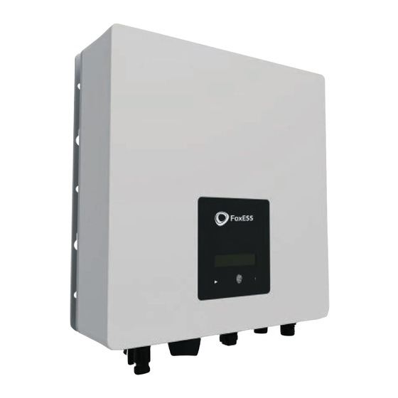
30 volts. 3. About Product 3.1 About S Series Inverter S series inverters cover 0.7kW systems up to 3.3kW and are integrated with 1 MPP tracker with high efficiency and reliability. 3.2 Basic Features ▪... -
Page 7: Terminals Introduction
3.3 Terminals Introduction Item Description DC Switch (Optional) Waterproof Lock Valve WiFi / GPRS AC Connector Ground Screw Note: Only authorized personnel are permitted to set the connection. 3.4 Dimensions For S Series: S Series User Manual www.fox-ess.com P a g e... -
Page 8: Technical Data
96.50% 96.80% 96.80% 96.80% 96.80% Max. efficiency 97.20% 97.20% 97.30% 97.40% 97.40% 97.40% 97.40% Safety & Protection DC Reverse-polarity protection Insulation monitoring DC injection monitoring AC Short-circuit protection Residual current detection S Series User Manual www.fox-ess.com P a g e... -
Page 9: General Data
Communication *India and Poland markets only. 5. Installation 5.1 Packing List Please un-pack the box, check and make sure you received all items as listed below before installation (excluding optional items): S Series User Manual www.fox-ess.com P a g e... -
Page 10: Preparation
Avoid electromagnetic interference that can compromise the correct operation of electronic equipment. ▪ The slope of the wall should be within ±5°. 5.3 Installation Space Required Position Min Size Left 30cm Right 30cm 30cm Bottom 30cm Front 30cm S Series User Manual www.fox-ess.com P a g e... -
Page 11: Tools Required
Hang the inverter over the bracket, slightly lower the inverter, and make sure the 2 mounting bars on the back are fixed with the 2 grooves from bracket properly. | 10 S Series User Manual www.fox-ess.com P a g e... -
Page 12: Wiring Steps
Step 1: PV String Connection S series inverters can be connected with 1-string of PV modules. Please select suitable PV modules with high reliability and quality. Open circuit voltage of module array connected should be less than 550V, and operating voltage should be within the MPPT voltage range. - Page 13 - When separating the DC - connector, push the tool down from the bottom. - Separate the connectors by hand. ➢ Grid Connection S series inverters are designed for single-phase grid. Voltage range is 220/230/240V; frequency is 50/60Hz. Other technical requests should comply with the requirement of the local public grid. Model S700...
- Page 14 Remove the AC connector, press the bayo-nut out of the slot with a small screwdriver or the unlock tool and pull it out, or unscrew the threaded sleeve, then pull it out. | 13 S Series User Manual www.fox-ess.com P a g e...
-
Page 15: Earth Connection
Screw the ground screw with screwdriver as shown below: 5.8 Communication Device Installation (Optional) This S Series inverter is available with multiple communication options such as WiFi, LAN, GPRS, RS485, and Meter with an external device. Operating information like output voltage, current, frequency, fault information, etc., can be monitored locally or remotely via these interfaces. - Page 16 For Meter installation, please install it on the grid side. Export limitation setting: Short press the touch key to switch display or make the Value+1. Long press the touch key to confirm your setting. | 15 S Series User Manual www.fox-ess.com P a g e...
-
Page 17: Inverter Start-Up
Please refer to the following steps to start-up the inverter: Check if device is fixed well on the wall; Model Socket Asserted by shorting pins Function DRM0 Operate the disconnection device ESTOP Emergency stop the inverter | 16 S Series User Manual www.fox-ess.com P a g e... -
Page 18: Inverter Switch Off
Please follow the below steps to switch off the inverter: Switch off the inverter AC isolation switch. Switch off the DC isolation switch and allow 5 minutes for the inverter to power down completely. | 17 S Series User Manual www.fox-ess.com P a g e... -
Page 19: Operation
The touch key is used to set the LCD to display different parameters. Press time <1s (short press): Next; Touch Key Press time >2s (long press): Enter. Wait time 15s: return to start | 18 S Series User Manual www.fox-ess.com P a g e... -
Page 20: Function Tree
6.2 Function Tree 7. Maintenance This section contains information and procedures for solving possible problems with the FoxESS inverters and provides you with troubleshooting tips to identify and solve most problems that can occur. 7.1 Alarm List Fault Code Solution... - Page 21 - Please seek for help from us if it cannot be detected or the impedance is <1Mohm. - Check the voltage of neutral and PE. Ground fault - Check AC wiring. - Restart inverter, if error message persists, seek for help from us. | 20 S Series User Manual www.fox-ess.com P a g e...
-
Page 22: Troubleshooting
Are the configurations settings correct for your particular installation? Are the display panel and the communications cable properly connected and undamaged? Contact FoxESS Customer Service for further assistance. Please be prepared to describe details of your system installation and provide the model and serial number of the unit. -
Page 23: Decommissioning
Please be sure to deliver any inverter that needs to be disposed from sites that are appropriate for the disposal in accordance with local regulations. | 22 S Series User Manual www.fox-ess.com P a g e... - Page 24 Ma i t i a n E n e r g y Co . , L t d Wu x i B r a n c h A d d : N o . 1 1 , L i J i a n g R o a d , X i n wu D i s t r i c t , Wu x i Ci t y , J i a n g s u P r o v i n c e , Ch i n a T e l : 0 5 1 0 - 6 8 0 9 2 9 9 8 WWW.
Need help?
Do you have a question about the S Series and is the answer not in the manual?
Questions and answers