Sundstrom SR 540 Operating Instruction
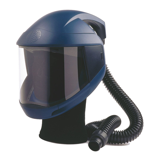
Face shield
Hide thumbs
Also See for SR 540:
- Instructions for use manual (57 pages) ,
- Operating instruction (23 pages) ,
- Product manual (8 pages)

Related Manuals for Sundstrom SR 540


Summary of Contents for Sundstrom SR 540
- Page 1 Drawn up by: 2009-01-26 / RK Revision: OI06H-0518 SR 540 Reviewed: 2014-02-05 / PA Page: 1 of 26 Operating instruction SR 540 Face Shield...
-
Page 2: General Information
Page: 2 of 26 General information The SR 540 together with fan unit SR 500 and approved filters are included in the Sundström fan-assisted respiratory protective device system conforming to EN 12941/EN 12942:1998 class TH3. SR 540 together with compressed air attachment SR 507 and breathing hose SR 358/SR 359/SR 360 are included in the Sundström compressed air-fed respiratory device system... - Page 3 Revision: OI06H-0518 SR 540 Reviewed: 2014-02-05 / PA Page: 3 of 26 2.1 Unpacking SR 540 2.2 Packing list Check that the equipment is complete in accordance with the packing list and has not been damaged in transport. Packing list: •...
- Page 4 Drawn up by: 2009-01-26 / RK Revision: OI06H-0518 SR 540 Reviewed: 2014-02-05 / PA Page: 4 of 26 Connect the end with the flat gasket to the face shield. Turn it clockwise about 1/8 of a turn. The hose is now connected to the face shield.
- Page 5 Drawn up by: 2009-01-26 / RK Revision: OI06H-0518 SR 540 Reviewed: 2014-02-05 / PA Page: 5 of 26 Remove the protective film from the visor. Secure the visor to the fixed mounting. Then put the visor to the over-centre mounting.
- Page 6 Drawn up by: 2009-01-26 / RK Revision: OI06H-0518 SR 540 Reviewed: 2014-02-05 / PA Page: 6 of 26 Tension the visor by moving the lever downward as far as it will go. Check that the visor is firmly in contact with the visor opening seal all around.
-
Page 7: Flow Control
Drawn up by: 2009-01-26 / RK Revision: OI06H-0518 SR 540 Reviewed: 2014-02-05 / PA Page: 7 of 26 Connect the hose to the fan unit and turn it clockwise about 1/ 8 of a turn. Flow control Place the head top in the flow meter and start the fan unit. - Page 8 Drawn up by: 2009-01-26 / RK Revision: OI06H-0518 SR 540 Reviewed: 2014-02-05 / PA Page: 8 of 26 2.4 Putting the face shield on Raise the visor and put the face shield If necessary, adjust the head harness in height by lengthening or shortening the...
- Page 9 Drawn up by: 2009-01-26 / RK Revision: OI06H-0518 SR 540 Reviewed: 2014-02-05 / PA Page: 9 of 26 If necessary, adjust the circumference of the head harness by means of the knob at the rear of the head harness. Lower the visor unit by pulling the face seal down under your chin.
- Page 10 Drawn up by: 2009-01-26 / RK Revision: OI06H-0518 SR 540 Reviewed: 2014-02-05 / PA Page: 10 of 26 Insert a finger between your chin and the face seal and run the finger along the contact surface of the face seal all the way round to check that it fits well against the face.
- Page 11 Drawn up by: 2009-01-26 / RK Revision: OI06H-0518 SR 540 Reviewed: 2014-02-05 / PA Page: 11 of 26 4 Maintenance 4.1 Cleaning/Disinfecting Sundström cleaning tissues SR 5226 that clean and disinfect are recommended for daily care. Clean face shield and visor...
- Page 12 Drawn up by: 2009-01-26 / RK Revision: OI06H-0518 SR 540 Reviewed: 2014-02-05 / PA Page: 12 of 26 Clean the valve seat and check that the valve seat is ok. Clean the exhalation membrane. Clean the valve cover on the inside and...
- Page 13 Drawn up by: 2009-01-26 / RK Revision: OI06H-0518 SR 540 Reviewed: 2014-02-05 / PA Page: 13 of 26 Clean around the mounting points for the visor. Clean around the opening seal. Clean the seal.
-
Page 14: Maintenance Schedule
Drawn up by: 2009-01-26 / RK Revision: OI06H-0518 SR 540 Reviewed: 2014-02-05 / PA Page: 14 of 26 Clean the face seal. 4.2 Storage After cleaning, store the equipment in a dry and clean place at room temperature. Avoid exposing it to direct sunlight. - Page 15 Drawn up by: 2009-01-26 / RK Revision: OI06H-0518 SR 540 Reviewed: 2014-02-05 / PA Page: 15 of 26 4.4.1 To change the exhalation membrane Snap of the valve cover from the valve seat. Slip off the membrane. Check that the valve seat is ok...
- Page 16 Drawn up by: 2009-01-26 / RK Revision: OI06H-0518 SR 540 Reviewed: 2014-02-05 / PA Page: 16 of 26 Press the new membrane onto the pin. Carefully check that the membrane is in contact with the valve seat all way round.
- Page 17 Drawn up by: 2009-01-26 / RK Revision: OI06H-0518 SR 540 Reviewed: 2014-02-05 / PA Page: 17 of 26 Release the visor by moving the lever of the over-centre lock upwards through about 180 degrees. Remove the visor. Remove the protective film from the new...
- Page 18 Drawn up by: 2009-01-26 / RK Revision: OI06H-0518 SR 540 Reviewed: 2014-02-05 / PA Page: 18 of 26 Secure the visor to the fixed mounting. Then put the visor to the over-centre mounting. Tension the visor by moving the lever...
- Page 19 Fit the closing panels by pushing them into place with your fingers. A clicking sound indicates that they are in place. 4.4.3 To change the face seal on the SR 540 Release the hooks from the head harness.
- Page 20 Drawn up by: 2009-01-26 / RK Revision: OI06H-0518 SR 540 Reviewed: 2014-02-05 / PA Page: 20 of 26 Release the face seal by pulling it´s frame so that its pins are released from the visor unit holes. Remove the face seal.
- Page 21 Drawn up by: 2009-01-26 / RK Revision: OI06H-0518 SR 540 Reviewed: 2014-02-05 / PA Page: 21 of 26 Thread it on the flange. Press the face seal frame down so that the pins drop into the visor unit holes. A clicking sound indicates that they are in place.
- Page 22 Drawn up by: 2009-01-26 / RK Revision: OI06H-0518 SR 540 Reviewed: 2014-02-05 / PA Page: 22 of 26 4.4.4 To change the sweatband Release the face seal hooks from the head harness. Pull the sweatband of. Fit the Velcro strip with the ruffled side towards the forehead strap and with relief upwards.
- Page 23 Drawn up by: 2009-01-26 / RK Revision: OI06H-0518 SR 540 Reviewed: 2014-02-05 / PA Page: 23 of 26 Fit the rest of the strip. Secure the hooks to the head harness where a relief has been made in the sweatband.
- Page 24 Drawn up by: 2009-01-26 / RK Revision: OI06H-0518 SR 540 Reviewed: 2014-02-05 / PA Page: 24 of 26 Fit the head cover Velcro strip towards the visor unit strip. Mounting peel of SR 542 Remove the protective film on the two self adhesive dots.
- Page 25 Drawn up by: 2009-01-26 / RK Revision: OI06H-0518 SR 540 Reviewed: 2014-02-05 / PA Page: 25 of 26...
- Page 26 Drawn up by: 2009-01-26 / RK Revision: OI06H-0518 SR 540 Reviewed: 2014-02-05 / PA Page: 26 of 26...
Need help?
Do you have a question about the SR 540 and is the answer not in the manual?
Questions and answers