Table of Contents
Advertisement
Quick Links
DOC 0915
INSTRUCTION MANUAL
FOR THE NIPPY JUNIOR +
POSITIVE PRESSURE
VENTILATOR
B & D Electromedical
Units A1-A2
The Bridge Business Centre
Timothy's Bridge Road
Stratford Enterprise Park
Stratford–upon-Avon,
Warwickshire. CV37 9HW
Tel: 01789 293460 Sales
01789 721577 Technical Support
Fax: 01789 262470
www.nippyventilator.com
Version 1, September 2007
Advertisement
Table of Contents

Related Manuals for Breas Medical Nippy Junior+


Summary of Contents for Breas Medical Nippy Junior+
- Page 1 DOC 0915 INSTRUCTION MANUAL FOR THE NIPPY JUNIOR + POSITIVE PRESSURE VENTILATOR B & D Electromedical Units A1-A2 The Bridge Business Centre Timothy’s Bridge Road Stratford Enterprise Park Stratford–upon-Avon, Warwickshire. CV37 9HW Tel: 01789 293460 Sales 01789 721577 Technical Support Fax: 01789 262470 www.nippyventilator.com Version 1, September 2007...
-
Page 2: Table Of Contents
NIPPY JUNIOR + INSTRUCTION MANUAL INDEX Page Operation Description Intended Use Features Explanation of Controls Fascia Buttons Fascia Display Outlets Rear Panel Layout Explanation of Symbols Used Getting Started The Main Screen How to Adjust The Nippy Junior + The Menu Window How to use the on-screen Menu Structure of the Main Menu Breath Analyser... -
Page 3: Description
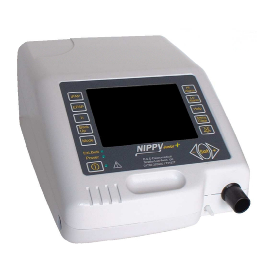
NIPPY JUNIOR + Positive Pressure Ventilator The Nippy jnr+ is a pressure controlled, positive pressure ventilator. It compresses ambient air and delivers it to the patient through a close fitting nasal mask or a tracheotomy. The output pressure, timing and alarms can be adjusted by controls on the fascia panel. - Page 4 Alarms Power Fail If the electrical power to the ventilator is interrupted, an audible alarm will sound. This alarm will run for 5 minutes unless cancelled with the mute button. Once cancelled the power fail alarm will not re-activate. Low Internal Battery When running on its internal battery, the alarm will operate when the battery is almost depleted The user cannot replace this battery.
- Page 5 Estimated Tidal Volume The estimated tidal volume is a calculated value, based on time and calibrated flow values. The constant leak through the breathing circuit exhalation port is subtracted from this calculation to give a reasonably accurate estimation of tidal volume. The estimated tidal volume is displayed above the bargraph display.
-
Page 6: Intended Use
Intended Use The Nippy jnr+ is designed to augment ventilation in children with acute or chronic type 2 respiratory failure. Patients who suffer form nocturnal hypoventilation are chiefly those with failure of the respiratory pump, though any concomitant lung disease is also deleterious. The main groups of patients who develop this problem are: - Patients with respiratory muscle weakness. -
Page 7: Features
FEATURES Lightweight, compact fully self-contained unit Internal battery operation Comprehensive, auto setting, alarms with mute facility Can be used with Nasal mask, Full face mask or tracheotomy. User friendly intuitive software Easily understood alarm messages displayed onscreen 4 modes of ventilation Employs state of the art microprocessor control Universal mains input, operates anywhere in the world without transformers Adjustable flow triggers with trigger indicators... -
Page 8: Explanation Of Controls
EXPLANATION OF CONTROLS Fascia Buttons 1. IPAP - Selects the Inspiratory Positive Airway Pressure adjustment (scaled in cm H 2 O). Value is displayed on screen adjacent to the switch. 2. EPAP - Selects the Expiratory Positive Airway Pressure adjustment (scaled in cm H 2 O). Value is displayed on screen adjacent to the switch. - Page 9 8. Set - Selects the current menu function displayed by the selection bar. OR double press for battery run time and hours till next service. +► - Increments the selected parameter or moves the selection bar up the menu 10. Mute Silences the alarm for 2 minutes.
-
Page 10: Fascia Display
Fascia Display 1 . Mode Displays current mode of ventilation. 2 . Pressure Display - Indicates airway pressure (scaled in cm H Changes colour to red in under / over pressure alarm condition. 3 . Rate Display - Indicates patient breath rate (scaled in Breaths Per Minute). -
Page 11: Outlets
Ventilator Outlets 1. Outlet Main Air Outlet to breathing circuit 2 . EVC Port Exhale Valve Control outlet Connected to the Exhalation valve in IPPV mode Leave disconnected in any other mode... -
Page 12: Rear Panel Layout
Rear Panel Layout Aux. Power 24 Volt connection for external battery. Connect only recommended batteries, part no 0910 RS232 Port For connection to remote alarm or personal computer. Isolated to 1500 Volts. Power Inlet Input mains power connector. Double fused and fitted with connector retaining clip. -
Page 13: Explanation Of Symbols Used
Explanation of Symbols used on Nippy jnr+ and Accessories Type B Applied parts to EN 60601-1 Alternating Current Direct Current Time Delay Fuse Serial Number Date of Manufacture Attention. Consult Accompanying Documents Switch ON /OFF +► Increase Button ◄- Decrease Button Locked / Unlocked, Purple = total lock, Black = settings locked Alarm Muted Battery charged... -
Page 14: Getting Started
Getting Started To Switch On Place the Nippy jnr+ on a clean, smooth, hard surface. (NOT carpet) Connect the power lead to the mains power connector on the rear panel. Plug into the mains power supply. Press the Start/Stop button. To Switch Off Press the Start/Stop button. -
Page 15: The Menu Window
Menu Window The Main Menu gives access to further adjustments and allows you to view information relating to the ventilator usage. How to use the on-screen menu Press the MENU button. The menu window will be displayed in front of the main screen. -
Page 16: Structure Of The Main Menu
Structure of the Main Menu 1. Adjust Trigger I Trig View / Adjust E Trig View / Adjust 2. User Preferences Alarm Volume View / Adjust Display Brightness View / Adjust Display Contrast View / Adjust Display Dimming View / Adjust (Sets time in minutes until display dims, to night time level) 3. -
Page 17: Breath Analyser
Breath Analyser The breath analyser changes the display to a graphical format, like an oscilloscope. This can be useful to evaluate a patient’s breathing pattern and to assess the effectiveness of the triggering. The pressure and flow waveforms are stored then displayed on the screen. The screen displayed shows the stored information from the previous breath. -
Page 18: How To Use The On-Screen Help
How to use the On-screen Help Press the HELP button at any time for a list of help topics. Follow the simple on- screen instructions. Press HELP again to exit. If during setting up, you require a description of a particular parameter, select it then press HELP. -
Page 19: Breathing Circuits And Masks
Breathing Circuits Always use a 22mm bore breathing circuit when the High Flow alarm is set above 80 lpm. Always use a 15mm bore breathing circuit when the High Flow alarm is set below 80 lpm. The type of breathing circuit used will depend on the mode of ventilation selected:- Breathing circuits to be assembled in the order A-B-C-D from the ventilator end. -
Page 20: Using The Nippy Junior+ Invasively
Using the Nippy Junior+ Invasively The Nippy Junior+ is safe for use with a tracheotomy or endotracheal tube. An exhalation port must be fitted between the breathing circuit and the tracheotomy fitting. DO NOT USE THIS TYPE OF CIRCUIT FOR IPPV MODE 15mm dry circuit, Part Number 0806 Breathing circuit volume = 470 ml including filter. -
Page 21: Setting Up
SETTING UP THE NIPPY JUNIOR + in CPAP MODE 1. Place the Nippy Junior + on a clean, level surface. 2. Connect the breathing circuit tube to the outlet. It is recommended that a bacterial filter be fitted between the outlet and the 22mm diameter breathing tube. 3. -
Page 22: Setting Up The Nippy Junior + In Pressure Support Mode
SETTING UP THE NIPPY JUNIOR + in PRESSURE SUPPORT MODE Before starting to set up the ventilator, assess the patients breathing pattern. You will need to know the breath rate. Place the Nippy Junior + on a clean, level surface. Connect the breathing circuit tube to the outlet. -
Page 23: Setting Up The Nippy Junior + In Pressure Control Mode
SETTING UP THE NIPPY JUNIOR + in PRESSURE CONTROL MODE Before starting to set up the ventilator, assess the patients breathing pattern. You will need to know the breath rate and the approximate inspiratory time (Ti). Place the Nippy Junior + on a clean and level surface. Connect the breathing circuit tube to the outlet. -
Page 24: Setting Up The Nippy Junior + In Ippv Mode
SETTING UP THE NIPPY JUNIOR + in IPPV MODE Before starting to set up the ventilator, assess the patients breathing pattern. You will need to know the breath rate and the approximate inspiratory time (Ti). Place the Nippy Junior + on a clean, level surface. Connect the breathing circuit tube to the outlet. -
Page 25: Setting Up The Alarms
Setting Up the Alarms Automatic Setting For convenience, the high and low flow alarms may be set automatically. Varying leak or the patient getting out of synch with the ventilator may disrupt the measurement process. Therefore it is vital that the alarms are tested after setting up. Low Flow Alarm Press and hold the Low Flow Alarm button •... -
Page 26: Alarm Conditions/Tests
Alarm Conditions/Tests Test the alarms prior to use or daily for machines that are in constant use. Before testing alarms, ensure that the alarm is not muted. To cancel the Mute, press and hold the mute switch until a beep is heard (2 seconds). High Flow Alarm If the inspiratory flow exceeds the high alarm value, the alarm will be activated accompanied by the on-screen, high flow alarm message. -
Page 27: Running On Battery Power
Running the Nippy Junior + on Battery Power Nippy jnr+ may be powered from the mains, external battery or internal battery. When running on mains, the ventilator will recharge its own internal and/or external battery. Charge time is normally around 8 to 11 hours, per battery, depending on the ventilator settings. - Page 28 The run time may be as long as 12 hours for low values of CPAP with only moderate leak, or as short as 4 hours for Pressure Support at maximum pressure with quite severe leaks. Battery run times will typically be 20% more in IPPV mode because of the absence of the exhale port leak.
-
Page 29: Internal Battery
Internal Battery Battery Test Test the battery if the running time seems low, a fault is suspected, or to confirm that the battery is good. • Ensure the battery is fully charged. • Run the ventilator from the battery until the low battery alarm operates and record the running time. -
Page 30: External Battery
External Batteries An external battery may be used to increase the running time. This battery is essentially the same as the internal battery and will power the ventilator for the same time, depending on settings and leak External Battery, part number 0910. External battery charger part number 0911 These batteries should never be used to run any other type of equipment. -
Page 31: Battery Care
Battery Care DO NOT use any other type of battery charger. This could lead to damage to the battery and personal injury. The battery should be recharged as soon as possible after use. • This type of battery does not suffer from the memory effect that is widely talked about •... -
Page 32: Connecting Auxiliary Equipment
Connecting auxiliary monitoring equipment For monitoring or downloading data the Nippy jnr+ may be connected to a PC or Laptop computer. The Nippy jnr+ isolated RS232 port is safe for use with any domestic PC or laptop computer. However, when assembling a system, the completed system should comply with EN60601-1 (medical systems). -
Page 33: Specifications
SPECIFICATIONS Supply Voltage 100 - 240 V alternating current Supply Frequency 47 - 63 Hz Maximum Input Current 0.40 – 1.0 Amperes Fuse Ratings 2 x T 1.6 A 20mm Dimensions (mm) Length - 297 Width - 223 Height - 132 Weight 4.5 kg 32 o C 90 o F Max... -
Page 34: Operation Under Extreme Conditions
Operation Under Extreme Conditions Ambient Temperature in the range of +5 to +50 Between 5 and 40 degrees functioning of the ventilator should not be affected. Extremes of temperature (below 5 C, above 40 C) may affect the colour of the LCD display. -
Page 35: Warnings And Cautions
WARNINGS This ventilator is intended to augment the patient breathing. It MUST NOT BE USED AS A LIFE SUPPORT VENTILATOR . It is not intended to provide the total ventilatory requirement of the patient Do not attempt to pass oxygen into the panel mounted air inlet, or use with flammable anaesthetic agents e.g. -
Page 36: User Maintenance
USER MAINTENANCE YOU MUST DISCONNECT THE NIPPY FROM THE MAINS SUPPLY BEFORE ANY MAINTENANCE IS CARRIED OUT User maintenance is limited to cleaning and visual inspection of the ventilator, the input air filter and the breathing circuit. The ventilator and the detachable mains cord set should be inspected for signs of external damage weekly. -
Page 37: Servicing
Servicing Only suitably qualified technically competent personnel should attempt servicing of this ventilator. To maintain its performance, the ventilator will require periodic servicing at the following intervals: - Annual electrical safety test 10000 hours use. The service reminder symbol will be displayed on screen. Details of service requirements are contained in the technical manual. -
Page 38: Locking The Settings
Locking the settings Adjustment lock The settings can be locked to prevent unauthorised adjustment. ◄- +► To lock press buttons simultaneously and hold for 2 seconds. ◄- +► To unlock press buttons simultaneously and hold for 2 seconds. This prevents adjustment but allows the user to switch the ventilator on and off. Total lock The ventilator can be locked to prevent unauthorised adjustment or power off.
Need help?
Do you have a question about the Nippy Junior+ and is the answer not in the manual?
Questions and answers