Table of Contents
Advertisement
Doc 0930
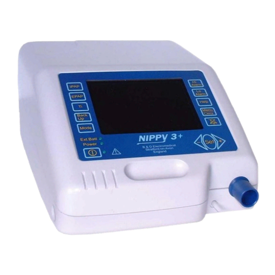
NIPPY+ Range of Ventilators
This manual covers all of the NIPPY+ range of ventilators
This manual contains confidential information
and it is supplied on the understanding that it
shall not be copied, loaned or distributed to any
other persons or organisations, in whole or in
part, without the written consent of:
Unit A2, The Bridge Business Centre
Version 10, December 2017
Technical Manual
for the
Breas Medical Ltd
Timothy's Bridge Road
Stratford–upon-Avon
CV37 9HW
Tel: 01789 293460
www.nippyventilator.com
Advertisement
Table of Contents

Subscribe to Our Youtube Channel
Related Manuals for Breas Medical NIPPY+ Series


Summary of Contents for Breas Medical NIPPY+ Series
- Page 1 Breas Medical Ltd Unit A2, The Bridge Business Centre Timothy’s Bridge Road Stratford–upon-Avon...
-
Page 2: Table Of Contents
Contents Introduction Description 2 - 5 Service Menus Time and Date Service Period / Calibration Diagnostic Screen Alarm Log Install Defaults Fault Messages 11-12 Event Log Opening the Case Fig 1, Opening the Case Fig 2, Inside the base Fig 3, Inside the base – Control bd removed Fig 4, Location of Components –... -
Page 3: Introduction
IMPORTANT Read this manual before attempting service or repair of the NIPPY+ Please contact Breas Medical Ltd if training is required or you have any questions. NIPPY+ must be subjected to regular inspection according to Breas Medical Ltd service instructions. Repairs shall be carried out in accordance with this technical manual and any special service instructions or bulletins provided by Breas Medical Ltd. -
Page 4: Description
Description The NIPPY+ range ventilators are intended to provide ventilation for non- dependent, spontaneously breathing adult patients with respiratory insufficiency, or respiratory failure. The NIPPY+ range devices are pressure controlled, positive pressure ventilators. They compress ambient air and deliver it to the patient through a close fitting nasal mask or a tracheostomy. - Page 5 Modes of Ventilation CPAP (Continuous Positive Airway Pressure) Constant positive pressure is applied via the mask. No respiratory support is given in this mode. NIPPY 3+, NIPPY Junior+, NIPPY ST+. Pressure Support IPAP (Inspiratory positive airway pressure) and EPAP (Expiratory positive airway pressure) are set by the physician.
- Page 6 Alarms Power Fail If the electrical power to the ventilator is interrupted, an audible alarm will sound. This alarm will run for 5 minutes unless cancelled with the mute button. Once cancelled the power fail alarm will not re-activate. Low Internal Battery When running on its internal battery, the alarm will operate when the battery is low.
- Page 7 Estimated Tidal Volume The estimated tidal volume is a calculated value, based on time and calibrated flow values. The constant leak through the breathing circuit exhalation port is subtracted from this calculation to give a reasonably accurate estimation of tidal volume. If a different exhalation port is used (a ventilated mask for example) this calculation may be affected by the possible change in exhalation port flow rate.
-
Page 8: Time And Date
The Service Menu Accessing the service menu To access the service menu, power up the machine whilst holding down the Hi and Lo alarm setting buttons (Menu and Mute on NIPPY S+ and ST+). Press Menu and select Service menu from the main menu. Set Time and Date Press the set button to select the value and use the + and –... -
Page 9: Service Period / Calibration
Service Period The service period screen shows the total running time and running time since the last major service. When a 10000 hour service has been completed, press the + and – buttons together for 2 seconds. The current date will be entered into the service record and the service indicator will be reset. -
Page 10: Diagnostic Screen
Diagnostic Screen This screen shows the following information:- Box internal temp The internal temperature. If this value rises above 60 degrees, an alarm will be activated. Blower current Current consumed by the blower Pressure Error The pressure servo loop error. This should ideally be close to zero. -
Page 11: Alarm Log
Alarm Log The alarm log shows the number of alarm events and the time and date of the last occurrence. Alarm Log Entry Explanation “Over Pressure” Pressure exceeded 120% of IPAP setting "Under Press." Pressure failed to reach 50% of set IPAP level "High Flow"... -
Page 12: Install Defaults
Install Defaults If the ventilator is to be re-used for a different patient, the settings may be restored to the factory defaults. These are:- NIPPY 3+ NIPPY Junior+ IPAP 12cm 12cm EPAP Ti back-up 1.0 seconds 1.0 seconds Mode Pressure Support Pressure Support Hi Alarm 100L/min... -
Page 13: Fault Messages
Fault messages Fault Message Fault Log Entry Explanation Probable Cause Possible Remedy Pressure Measurement "Press.Meas.Flt" Loss of pressure signal Pressure transducer pipe Reconnect pipe and restart fault disconnected. machine. Pressure transducer fault. Replace power board. Technical Fault Safe Mode Ventilator has set to minimum output Pressure transducer pipe Reconnect pipe and restart Vent Now in Safe Mode... - Page 14 Fault Message Fault Log Entry Explanation Probable Cause Possible Remedy "Alarm PIC Flt." Communication error with alarm micro. Power interruption has No action required. Unless caused communication there are multiple occurrences, error. then change command board Alarm back up battery "Alarm PIC Bat."...
-
Page 15: Event Log
The Event Log The ventilator automatically stores every event during its lifetime. This event log is not displayed on-screen but may be downloaded to a PC using download lead part no. 0858. The following events will be stored in the memory:- Power on / off Power interruptions Any button push... -
Page 16: Fig 1, Opening The Case
Opening the Case IMPORTANT Disconnect the ventilator from the mains supply and / or any external battery. Invert the ventilator and remove the seven recessed, hexagon socket screws. Stand the ventilator on its base and ease the lid upwards, away from the rear panel. -
Page 17: Fig 2, Inside The Base
Fig 2. Inside the Base 1. Mains Power Supply 9. Pressure Transducer 2. Battery Clamp 10. Flow Transducer 3. Battery 11. Flow Head 4. Internal Battery Connector 12. Patient Outlet Port 5. Blower Connector 13. IPPV Exhale Valve Control Line (NIPPY 3+ and jnr+ only) 6. -
Page 18: Fig 3, Inside The Base - Control Bd Removed
Fig 3. Inside the base with the control board removed... -
Page 19: Fig 4, Location Of Components - Lid
Fig 4. Inside the Lid 1. RS 232 Port 6. Keypad Connector 2. Board to Board Ribbon 7. Alarm Sounder Connector 8. Display Back-light Connector 3. Memory Battery Switch (Output) 4. Display Connector 9. Second Alarm Sounder 5. Display Back-light Connector 10. -
Page 20: Removal Of Major Components
Removal of major components IMPORTANT Before opening the case, disconnect the NIPPY+ from the mains supply. Do not work on the NIPPY+ with the case open and the power supply connected. Make sure that all precautions to prevent Electrostatic Discharge (ESD) have been taken. - Page 21 Connect the Cooling fan, the blower, the internal and external and Battery connectors. Connect the pressure and flow transducers tubes as follows:- Longest (clear) tube from rear port of flow-head to the flow transducer port P1 (rear) Green tinted tube from front port on flow-head to front port of pressure transducer.
-
Page 22: Preventative Maintenance Guide
Preventative Maintenance Guide Maintenance levels will vary according to environmental conditions, duty cycle and pressure settings. This preventative maintenance guide has been written to assist in preparing maintenance schedules. Before use Check condition of the mains lead and connector. Check inlet air filter (Replace if necessary). Test alarm functions. - Page 23 Cleaning the Flow Head Not applicable to later models using a moulded flow head/outlet pipe. Depending on the age of the NIPPY+ it may be fitted with a flow head which uses a stainless steel gauze to restrict the airflow slightly and cause a flow of air through the flow transducer.
-
Page 24: Suggested Acceptance Tests
Suggested Acceptance Test Visual Inspection Check the NIPPY+ for transit damage. Functional Tests Connect a breathing circuit and test lung to the patient outlet and check function of modes. Maximum Pressure Set IPAP to maximum and ensure NIPPY+ achieves set pressure. Alarm tests Disconnect the breathing circuit and allow the flow to exceed the high flow alarm. -
Page 25: Internal Battery
Internal Battery Battery Life The end of life is defined by the maximum running time falling to 75% of that of a new battery. Run time will vary according to the ventilator settings so it is important that the users follow the battery care recommendations so that an aging battery can be identified and reported at the appropriate time. -
Page 26: Replacement Of Alarm Battery
Replacement of the pcb mounted Alarm Battery Open the case. See fig 1. Locate the battery switch on the command board (Item 3, fig 4) marked SW3 on the pcb. When viewed from the front, the right hand DIP switch (marked BATT on the pcb) is the battery isolation switch. -
Page 27: Calibration
Calibration of Pressure and Flow reading. Accurate calibration of the pressure and flow measurement is essential to the operation of the control pressure and alarms. Connect the patient outlet to a calibrated pressure and flow standard, using 22mm dia. smoothbore tubing, with no leak between the ventilator and calibrator. Enter the calibration screen Set the blower speed to 0%. -
Page 28: Theory Of Operation
Theory of operation The ventilator is powered by 24Vdc, derived from the mains (via an internal power supply) or an internal or external battery. A 10 volt instrumentation supply and 5 volt logic supply is derived from the 24 volts via on board regulators. -
Page 29: System Pneumatic Diagram
Ventilator System Pneumatic Diagram 1. Fresh air inlet 2. Blower (compressor) Flow Sensor Outlet connector EVC Port (IPPV mode only) Breathing Circuit 7. Exhalation Port 8. Patient Connection Port 9. Exhalation Valve (IPPV mode only) -
Page 30: Block Diagram
NIPPY 3+ BLOCK DIAGRAM Display/ User Interface RS232 Microprocessor Alarm Alarm Port Microcontroller Command Board EVC Solenoid Valve Microcontroller Control Electronics Blower Power Board Flow Transducer Flow Head Pressure Transducer IPPV mode Patient Outlet Port Port... -
Page 31: Block Diagram Of Control Board
Block Diagram of Nippy 3+ Control Board Solenoid Control Micro Blower Drive Pressure Battery Control/ Charging Pressure Flow Transducer Transducer... -
Page 33: Circuit Diagrams
Circuit Diagrams... - Page 35 0901...
- Page 36 0901...
- Page 37 0756...
-
Page 45: Specification
SPECIFICATIONS Supply Voltage 100 - 240 V alternating current Supply Frequency 47 - 63 Hz 0.40 – 1.0 Amperes Maximum Input Current Fuse Ratings 2 x T 1.6 A 20mm Length – 297, Width – 223, Height - 132 Dimensions (mm) Weight 3.6 kg (4.5 kg with internal battery) 40 o C 104 o F Max... -
Page 46: Spare Parts List
Spare Parts Case 316-11 PCB assy Control Board 0900 PCB assy Command Board 0754D Power supply 10007350 Cable Assy Mains 0767E Cable Assy PSU Harness 0770C Cable Assy Battery Link 0771D Cable Assy RS232 0779 Cable Assy Board Interconnect 0786B Cable Assy Inverter connector 0799A Membrane switch panel...
Need help?
Do you have a question about the NIPPY+ Series and is the answer not in the manual?
Questions and answers