Table of Contents
Advertisement
Quick Links
Table of Contents
1
Introduction ..................................................................................................................... 3
1.1
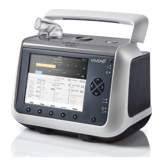
What is the Vivo 45? ......................................................................................... 3
1.2
Intended Use..................................................................................................... 5
1.3
Intended Environment ....................................................................................... 5
1.4
Intended Users.................................................................................................. 5
1.5
Contraindications ............................................................................................. 6
1.6
About this Manual ............................................................................................. 8
1.7
Manufacturer Information .................................................................................. 9
2
Safety Information......................................................................................................... 11
2.1
General User Precautions............................................................................... 11
2.2
Electrical Safety .............................................................................................. 14
2.3
Environmental Conditions ............................................................................... 15
2.4
Usage of Patient Circuit .................................................................................. 17
2.5
Usage of Filters ............................................................................................... 19
2.6
Humidification.................................................................................................. 20
2.7
Cleaning and Maintenance ............................................................................. 22
2.8
Usage of Oxygen ............................................................................................ 23
3
Product Description....................................................................................................... 25
3.1
Main Components ........................................................................................... 25
3.2
The Front Panel ............................................................................................ 27
3.3
The Side Panels.............................................................................................. 28
3.4
Equipment Designation ................................................................................. 32
4
Preparing the Vivo 45 for Use ...................................................................................... 35
4.1
Checking the Vivo 45 before First Use............................................................ 35
4.2
Placing the Vivo 45 ......................................................................................... 36
4.3
Connecting the Vivo 45 to Mains .................................................................... 38
4.4
Connecting the Patient Circuit......................................................................... 39
4.5
Inspecting the Vivo 45 before Use ................................................................. 39
4.6
Adjusting the Vivo 45 Patient Settings ............................................................ 40
4.7
Performing the Pre-use Test ........................................................................... 41
5
How to Use the Vivo 45 ................................................................................................ 43
5.1
Switch the Vivo 45 On and Off ........................................................................ 43
5.2
Using the Menu ............................................................................................... 47
5.3
Monitored Values in the Vivo 45 .................................................................... 56
5.4
Functions and Parameters in the Vivo 45 ....................................................... 61
5.5
Modes in the Vivo 45....................................................................................... 74
5.6
Using Batteries................................................................................................ 79
5.7
Using Accessories........................................................................................... 85
6
Alarms......................................................................................................................... 105
6.1
Alarm Function .............................................................................................. 105
6.2
Operator's Position........................................................................................ 107
6.3
Physiological Alarms ..................................................................................... 108
6.4
Technical Alarms........................................................................................... 133
6.5
Alarm Test..................................................................................................... 165
Doc.006149 En Y-2
Vivo 45 User Manual
1
Advertisement
Table of Contents

Related Manuals for Breas Medical Vivo 45


Summary of Contents for Breas Medical Vivo 45
-
Page 1: Table Of Contents
Adjusting the Vivo 45 Patient Settings ............40 Performing the Pre-use Test ................41 How to Use the Vivo 45 ....................43 Switch the Vivo 45 On and Off ................ 43 Using the Menu ....................47 Monitored Values in the Vivo 45 ..............56 Functions and Parameters in the Vivo 45 ............ - Page 2 Cleaning and Maintenance ..................169 Cleaning the Vivo 45 ..................170 Cleaning and Replacing the Air Filters............172 Change of Patient ..................173 Regular Maintenance Control ............... 174 Service and Repair..................174 Storage ......................174 Disposal ......................175 Technical Specifications ..................... 177 System Description ..................
-
Page 3: Introduction
Every other use may lead to risk of personal injury! CAUTION! Read this operating manual thoroughly so that you completely under- stand how the Vivo 45 is operated and maintained before taking it into use, to ensure correct usage, maximum performance and ser- viceability. Non-professional caregivers (e.g. family members) should consult the medical equipment provider’s respiratory thera-... - Page 4 Volume • CPAP – Continuous Positive Airway Pressure The Vivo 45 should be used with a leakage circuit and a suitable patient interface. For invasive use, the patient interface may be a tracheostomy tube (cuffed or uncuffed) and for non-invasive use it may be a mask, mouthpiece or pillow interface.
-
Page 5: Intended Use
Vivo 45 is intended for spontaneously breathing patients. 1.3 Intended Environment The Vivo 45 is intended to be used in clinical settings (e.g. hospitals, sub- acute care institutions), public spaces and home environments as well as during portable applications such as wheelchairs, personal family vehi- cles, ground ambulances and civil aircraft, excluding helicopters. -
Page 6: Contraindications
Day-to-day caregivers, patients, relatives and other non-professional users that operate the Vivo 45 within the prescribed settings. The lay operator shall be trained to basic knowledge of the Vivo 45 and in the specific operations they are assigned to perform. - Page 7 Patients should report any unusual chest pain, severe headache or increased breathlessness. The following side effects may occur during the course of therapy with the Vivo 45, patients are advised to report any new or changing adverse effects to their physician: • Nasal, mouth or throat dryness •...
-
Page 8: About This Manual
1.6 About this Manual Always read this manual before setting up and using the Vivo 45 or per- forming maintenance on the machine, to ensure correct usage, maxi- mum performance and serviceability. Audience This manual is intended for patients and other lay users operating the Vivo 45. -
Page 9: Manufacturer Information
Address Breas Medical AB Företagsvägen 1 SE-435 33 Mölnlycke Sweden Web Address www.breas.com E-mail address breas@breas.com Phone +46 31 868800, Order: +46 31 868820, Technical support: +46 31 868860 +46 31 868810 Introduction Vivo 45 User Manual Doc.006149 En Y-2... - Page 10 10 Introduction Vivo 45 User Manual Doc.006149 En Y-2...
-
Page 11: Safety Information
• Do not use the Vivo 45 in the event of suspected damage to the device, unexplainable or sudden pressure, performance or sound changes during operation, or if the delivered air from the Vivo 45 is abnormally hot or emits an odour. - Page 12 Vivo 45 operation before setting up and using the ventilator. • All the physiological alarms of the Vivo 45 must be set at safe levels that will effectively warn the user of any risk. The alarm levels should be assessed considering the settings and equipment used for the patient.
- Page 13 • The treatment settings should be reassessed periodically, for assuring therapeutic effectiveness. Safety Information Vivo 45 User Manual Doc.006149 En Y-2...
-
Page 14: Electrical Safety
2.2 Electrical Safety • Do not operate the Vivo 45 if it has a damaged power supply or cas- ing. • To avoid electrical shock, disconnect the electrical supply to the Vivo 45 before cleaning. Do not immerse the Vivo 45 into any fluids. -
Page 15: Environmental Conditions
Vivo 45 and pose unacceptable risk to the patient, medical staff or other persons. • Do not use the Vivo 45 while positioned in a warm place, such as direct sunlight or close to a radiator. Safety Information Vivo 45 User Manual Doc.006149 En Y-2... - Page 16 Vivo 45. Radio emitting devices are e.g. cellular or cordless tele- phones, microwave ovens and high-frequency surgery apparatus. – avoiding the use of the Vivo 45 in the presence of known EMI sources, including RF emitters (e.g. RFID, diathermy equipment).
-
Page 17: Usage Of Patient Circuit
• Periodically check for moisture in the patient circuit. When present, remove the moisture. Before attempting to dry the circuit, disconnect it from the Vivo 45 to ensure no water flows back into the Vivo 45. The frequency at which these checks must be performed will depend on the patient’s own condition and the device used. - Page 18 • To reduce the risk of rebreathing CO make sure that the leakage port is present as close as possible to the patient connection. • Always use a new patient circuit when the Vivo 45 is to be used by a new patient. 18 Safety Information Vivo 45 User Manual Doc.006149 En Y-2...
-
Page 19: Usage Of Filters
• When adding, changing or removing any kind of filter, always reas- sess the settings, including alarm settings and perform a pre-use test. • If the Vivo 45 is used in a setting where it will be used by multiple patients, a low resistance bacterial filter is recommended between the... -
Page 20: Humidification
• Any external humidifier connected to the Vivo 45 must comply with ISO 8185 or 80601-2-74. • Any HME connected to the Vivo 45 must comply with ISO 9360. • Do not add any attachments or accessories to the humidifier that are... - Page 21 • Certain HMEs and HCHs are sufficient to provide humidification when the Vivo 45 is used invasively. Check specific suppliers’ recom- mended use. The Vivo 45 has been tested and validated with the Fisher & Paykel MR850 heated humidifier. Safety Information Vivo 45 User Manual Doc.006149 En Y-2...
-
Page 22: Cleaning And Maintenance
• The Vivo 45 should be cleaned and maintained in accordance with this manual, see “Cleaning and Maintenance” on page 169. • Do not attempt to autoclave or sterilise the Vivo 45 main unit. • The Vivo 45 should not be serviced or maintained when in use. -
Page 23: Usage Of Oxygen
• The presence of oxygen can speed up combustion of inflammable materials. • When oxygen is used with the Vivo 45, the oxygen flow must be turned off when the Vivo 45 is not operating. Oxygen delivered into the patient tubing may accumulate within the ventilator enclosure. - Page 24 21%. If the oxygen concentration is higher, the monitored volume will deviate from the actual volume as follows: – 40% oxygen concentration: -2.5% deviation – 60% oxygen concentration: - 5% deviation – 80% oxygen concentration: -7.5% deviation 24 Safety Information Vivo 45 User Manual Doc.006149 En Y-2...
-
Page 25: Product Description
Product Description 3.1 Main Components The Vivo 45 medical electric equipment contains the following compo- nents: Product Description Vivo 45 User Manual Doc.006149 En Y-2... - Page 26 EU:003520 Power supply 006396 Vivo 45 main unit 220000 The standard Vivo 45 and its packaging do not contain any natural rub- ber latex. There might be local variations of the main components. 26 Product Description Vivo 45 User Manual...
-
Page 27: The Front Panel
Power source: External DC Click-in battery Power source: Click-in battery Internal battery Power source: Internal battery UTTONS UNCTION Navigation/Setting Navigation in current menu selec- tion/Define settings Function/Navigation Function according to display Information Show/Hide information Product Description Vivo 45 User Manual Doc.006149 En Y-2... -
Page 28: The Side Panels
Compartment for either of the accesso- ment ries click-in humidifier or click-in battery. Side panel Cover Carrying handle Handle for lifting the Vivo 45 Cooling air outlet Outlet internal cooling Cooling air inlet Inlet internal cooling 28 Product Description Vivo 45 User Manual... - Page 29 Memory download (SD card) Alarm Alarm Sounds Output Patient air inlet Air bypass unit in, replaceable filters Internal battery Compartment for the internal battery sensor hatch Compartment for the optional FiO sen- Product Description Vivo 45 User Manual Doc.006149 En Y-2...
- Page 30 To mount the filter side panel, insert the tabs (2) on the lower side of the panel into the holes (3). Press the side panel into the casing until it clicks in place at the but- ton (4). 30 Product Description Vivo 45 User Manual Doc.006149 En Y-2...
- Page 31 To mount the click-in compartment side panel, insert the tabs (2) on the lower side of the panel into the holes (3). Press the side panel into the casing until it clicks in place at the but- ton (4). Product Description Vivo 45 User Manual Doc.006149 En Y-2...
-
Page 32: Equipment Designation
Remote start/stop, Audio pause, and effort belt interface port Remote alarm and Nurse call interface port Network connection port USB data connection port Mains/External DC inlet 32 Product Description Vivo 45 User Manual Doc.006149 En Y-2... - Page 33 Symbols This section describes symbols and markings that might appear on the parts or packaging of the Vivo 45. YMBOL XPLANATION Internal battery Product number Read user instructions. Attention: Read the intended use in the manual. Read the Safety chapter in the manual.
- Page 34 CE marking applies in accordance with the direc- tive MDD 93/42/EEC, as amended by 2007/47/ Do not obstruct air inlets or outlet. Single patient use Hot Surface. Do not touch. (Heating plate in click-in compartment) 34 Product Description Vivo 45 User Manual Doc.006149 En Y-2...
-
Page 35: Preparing The Vivo 45 For Use
Ensure that the equip- ment is in good condition. If stored more than 1 month, connect the Vivo 45 to the power sup- ply to recharge the internal battery. Check that the grey and white air filters are installed. -
Page 36: Placing The Vivo 45
4.2 Placing the Vivo 45 Read the chapter “Environmental Conditions” on page 15 carefully to make sure all conditions are met and considered. Place the Vivo 45 on a solid, flat, and clean surface. – The Vivo 45 should be placed... - Page 37 Never cover the device. • Always position the Vivo 45 so the power supply lays on a surface without strain to the power cord. The power supply shall be easy to disconnect, if required to isolate the Vivo 45 from the mains.
-
Page 38: Connecting The Vivo 45 To Mains
Connect the power supply’s cord to the mains supply. To isolate the Vivo 45 from the mains supply, disconnect the power sup- ply. 38 Preparing the Vivo 45 for Use Vivo 45 User Manual... -
Page 39: Connecting The Patient Circuit
• Check that the cables are properly connected. Inspection of Placement • The Vivo 45 shall be placed on solid flat surface below the patient level (see “Placing the Vivo 45” on page 36). • Make sure that nothing can block the air inlet at the side. -
Page 40: Adjusting The Vivo 45 Patient Settings
Press and hold the Start/Stop button until the progress bar is filled. Check that a beep is heard when the Vivo 45 is started. This is the alarm beeper test, if there is no signal, do not use the Vivo 45 and con- tact your service provider. -
Page 41: Performing The Pre-Use Test
Always perform a new pre-use test if the patient circuit configuration has been changed. If the pre-use test has not been performed, the Vivo 45 will operate with default patient circuit compensation. The compliance is used for correcting the volume of air delivered to the patient by subtracting the air retained in the patient circuit during pressur- ization. - Page 42 Connect the patient circuit. Make sure that nothing is blocking the patient end of the cir- cuit. Wait while the Vivo 45 is checking the patient circuit resist- ance. Block the end of the patient circuit with an air tight object.
-
Page 43: How To Use The Vivo 45
Select Yes/No when asked to “Perform Pre-use Test”. (The Vivo 45 may be configured to not ask for pre-use test at start up. See “The Others Section” on page 53.) How to Use the Vivo 45 Vivo 45 User Manual Doc.006149 En Y-2... - Page 44 Select Start Ramp using the Up and Down arrow buttons and then Start the ramp by pressing the Right Arrow button. Confirm to start the ramp. 44 How to Use the Vivo 45 Vivo 45 User Manual Doc.006149 En Y-2...
- Page 45 Select Stop Ramp using the Up and Down arrow buttons and then stop the ramp by pressing the Right Arrow button. Confirm to stop the ramp. How to Use the Vivo 45 Vivo 45 User Manual Doc.006149 En Y-2...
- Page 46 Press “Ok” or the Audio Pause button to stop the treatment. To cancel the stopping process and continue the treatment, press “Cancel”. 46 How to Use the Vivo 45 Vivo 45 User Manual Doc.006149 En Y-2...
-
Page 47: Using The Menu
Use the left and right buttons to alter parameters, or enter and exit sub sec- tions. How to Use the Vivo 45 Vivo 45 User Manual Doc.006149 En Y-2... - Page 48 “Off”. SpO2 sensor connected connected EtCO connected PtcCO connected Effort belt connected Connection failures are indicated by red coloured belts. Multiple pages Multiple content available 48 How to Use the Vivo 45 Vivo 45 User Manual Doc.006149 En Y-2...
- Page 49 High priority alarm event in history list Medium priority alarm event in history list Size and colour of symbols may vary depending on displayed view. Menu Overview Home Mode In Home Mode, the Vivo 45 menu has the following section layout: Main Setup Setup 1-2 Alarm...
- Page 50 The Vivo 45 Main Display, Home Mode Indication of home mode lock status. See “Symbols Used in the Menu” on page 48 for information about each icon. When more than 1 profile is used, the active profile is displayed. Indication of battery status and connected sensors. See “Symbols Used in the Menu”...
- Page 51 The Setup Section In the Setup section, treatment parameters can be viewed. See “Functions and Parameters in the Vivo 45” on page 61. If Home Adjust is activated, some parameters might be adjustable within ranges defined by the prescribing physician. Adjustable parameters are indicated by green text.
- Page 52 The Alarms section contains 3 pages: The two first are for viewing alarm settings and the third is for viewing the alarm and message history. Shift between the pages by pressing the Alarm button. 52 How to Use the Vivo 45 Vivo 45 User Manual Doc.006149 En Y-2...
- Page 53 The monitoring page contains bargraphs for pressure and volume, and a field with measurement readings for the monitored values that are appli- cable for the treatment mode. See “Monitored Values in the Vivo 45” on page 56 for a description on the monitored values.
- Page 54 Patient Operating Time Shows the number of hours a patient has been using the Vivo 45 for breathing therapy. Compliance Data • Min Daily Use (Off, 1...24 h) • Start Date • Total Usage Hours • Total Days • Days with Usage •...
- Page 55 • Device Operating Time (hours) • Firmware Version • Language: Clinical Mode • Language: Home Mode • ~ AC (On/Off) • External DC (V) • Serial Number How to Use the Vivo 45 Vivo 45 User Manual Doc.006149 En Y-2...
-
Page 56: Monitored Values In The Vivo 45
5.3 Monitored Values in the Vivo 45 Values monitored by the Vivo 45 can be found in: The monitoring screen 56 How to Use the Vivo 45 Vivo 45 User Manual Doc.006149 En Y-2... - Page 57 Expired Tidal Volume that the patient exhales during each breath. is a calculated value. When the Vivo 45 is used non-invasively, the Vt can differ from the exhaled minute volume from the patient due to leaks around the mask.
- Page 58 Vivo 45. An FiO sensor needs to be in place to measure and display this value (see “Using the Vivo 45 with the FiO2 Sensor” on page 87). % in TgV The % in TgV displays the percentage of breaths where the actual delivered Tidal Vol- ume matches with the set Target Volume.
- Page 59 SpO module accessory. • When using the Vivo 45 with the SpO sensor accessory, the Vivo 45 displays functional oxygen saturation measured by the sensor. • The following information concerns the light emitted by the SpO2 Sensor: –...
- Page 60 The InspCO displays the inspired carbon dioxide. PtcCO The PtcCO2 displays transcutaneous CO pressure from an external PtcCO2 monitor, if connected by the PtcCo2 cable accessory. 60 How to Use the Vivo 45 Vivo 45 User Manual Doc.006149 En Y-2...
-
Page 61: Functions And Parameters In The Vivo 45
5.4 Functions and Parameters in the Vivo 45 All the parameters used for controlling the breathing by the Vivo 45 are listed below. Depending on the setup for Home mode adjustment, parameters may not be available or have limited ranges when the Vivo 45 is in Home mode. - Page 62 Breath Rate ESCRIPTION Definition The Breath Rate setting defines the mini- mum number of breaths the Vivo 45 will deliver as long as no inspiratory trigger effort from the patient is detected. The cycles will be ventilator-initiated breaths. The combination of the Breath Rate and Inspiratory Time setting is limited by the I:E ratio range 1:9.9 to 2:1.
- Page 63 Time and Backup Rate setting is limited by the I:E ratio 2:1. Setting min 0.3 s Setting max 5 s (Adult), 2 s (Paediatric) Setting resolution 0.1 s Display How to Use the Vivo 45 Vivo 45 User Manual Doc.006149 En Y-2...
- Page 64 A high setting will give a slow increase and therefore a shorter plateau. Setting min Setting max Setting resolution 1 Display 64 How to Use the Vivo 45 Vivo 45 User Manual Doc.006149 En Y-2...
- Page 65 Off. Setting min Setting max 9 (PSV), 9, Off (PCV) Setting resolution 1 (Setting 1 is the most sensitive and 9 is the least sensitive) Display How to Use the Vivo 45 Vivo 45 User Manual Doc.006149 En Y-2...
- Page 66 Expiratory Trigger. Setting min Off, 0.3 s Setting max 3 s (Adult), 2 s (Paediatric) Setting resolution 0.1 s Display 66 How to Use the Vivo 45 Vivo 45 User Manual Doc.006149 En Y-2...
- Page 67 ESCRIPTION Definition The Backup Rate setting defines the mini- mum number of breaths the Vivo 45 will deliver in case of prolonged apnea and as long as no inspiratory trigger effort from the patient has been detected. The cycles will be ventilator-initiated breaths.
- Page 68 ESCRIPTION Definition The Target Volume setting defines the tidal volume that the Vivo 45 will aim for while ventilating the patient in a pressure mode. To aim for the preset volume, the Vivo 45 will adapt the Inspiratory Pressure between two adjustable pressure limits: Min Pressure and Max Pressure.
- Page 69 Vivo 45 can increase the pressure to reach the set Target Volume. If Target Vol- ume is not reached at Max Pressure, the Vivo 45 will continue to ventilate at this Max Pressure setting. Setting min Min Pressure...
- Page 70 The Min Pressure setting is only used when Target Volume is activated. Min Pressure defines the lower pressure limit down to where the Vivo 45 can decrease the pressure to maintain the set Target Volume. If the actual volume is above Target Volume at Min Pressure, the Vivo 45 will continue to ventilate at this Min Pressure setting.
- Page 71 Insp. pressure – 2 cmH Always Start Ramp ESCRIPTION Definition The Always Start Ramp determines whether the ramp is started automatically at the beginning of the treatment. Setting min Setting max How to Use the Vivo 45 Vivo 45 User Manual Doc.006149 En Y-2...
- Page 72 See “Using the Patient Circuit with Heated Wire” on page 104. Setting min 16 °C (61 °F) Setting max 30 °C (86 °F) Setting resolution 0.5 ° 72 How to Use the Vivo 45 Vivo 45 User Manual Doc.006149 En Y-2...
- Page 73 The Heated Circuit needs to be connected before the setting can be turned On. See “Using the Patient Circuit with Heated Wire” on page 104. Setting min Setting max How to Use the Vivo 45 Vivo 45 User Manual Doc.006149 En Y-2...
-
Page 74: Modes In The Vivo 45
Standby and Operating Mode Standby mode is defined as the state of the Vivo 45 when it is powered on but without having treatment or pre-use test started. Operating mode is defined as the state of the Vivo 45 when the blower is operating and producing an air flow. - Page 75 The default settings and alarm limits of the Vivo 45 are preset when the patient mode is altered. Ventilation and Breath Modes The ventilation and breath modes are used for controlling the ventilation treatment with the Vivo 45.
- Page 76 The PSV(TgV) mode acts as the PSV mode but with an added regulation of the pressure. Target volume is a feature that automatically adapts the pressure to make sure that the Vivo 45 delivers the desired set target vol- ume to the patient. The delivered volume is compared to the set target volume on a breath by breath basis.
- Page 77 The PCV(A+TgV) mode acts like the PCV(A) mode, but with an added regulation of the pressure. Target volume is a feature that automatically adapts the pressure to make sure that the Vivo 45 delivers the desired set target volume to the patient. The delivered volume is compared to the set target volume on a breath by breath basis.
- Page 78 Time Insp. Time Backup Rate Target Volume Max Pressure Min Pressure CPAP 78 How to Use the Vivo 45 Vivo 45 User Manual Doc.006149 En Y-2...
-
Page 79: Using Batteries
It has long expected lifetime, low weight in relation to its capacity and low self discharge. See the Vivo 45 Service Manual on how to perform service on the batteries. Power Source Priority... - Page 80 – Information message “Switched to External DC” will be posted Charging the Batteries Do not charge the Vivo 45 while placed in the carry bag or other types of closed or non-ventilated spaces. Charging of batteries is only started when the state of charge is below 95%.
- Page 81 The click-in battery is intended as a power source during transportation, or if the primary AC power source fails. The click-in battery can be replaced during treatment, provided that the internal battery is charged. How to Use the Vivo 45 Vivo 45 User Manual Doc.006149 En Y-2...
- Page 82 When removing the battery, press down the latch at the bottom of the battery compartment and tilt the Vivo 45 sideways. Make sure to close the side panel after removing the click-in battery. 82 How to Use the Vivo 45 Vivo 45 User Manual Doc.006149 En Y-2...
- Page 83 Battery Operating Time (Internal and Click-in) The operation time is dependent on the battery condition, its capacity, the ambient air temperature and the Vivo 45 pressure setting. These data are based on new and fully charged batteries. ARAMETER XAMPLE NVIRONMENTAL...
- Page 84 5 to 30°C (41 to 86°F). External DC Do not connect the Vivo 45 to a wheelchair unless the operating manual for the wheelchair permits this as this can affect the Vivo 45 performance and consequently result in patient death.
-
Page 85: Using Accessories
Make sure to insert the connector with the marking pointing upwards. Pull the connector sleeve, not the cable itself or cable restrainer to release the connector. How to Use the Vivo 45 Vivo 45 User Manual Doc.006149 En Y-2... - Page 86 Using the Vivo 45 with a Nurse Call System The Vivo 45 can be connected to a nurse call system using the nurse call cable. When connected, the Vivo 45 alarms will also be forwarded to the nurse call system.
- Page 87 Shelf life 6 months Note that the operating conditions for the FiO sensor is different from the Vivo 45 system conditions. If the sensor is used outside its operating conditions the FiO measurements might deviate. How to Use the Vivo 45 Vivo 45 User Manual Doc.006149 En Y-2...
- Page 88 Reinstall the hatch. Calibrate the FiO sensor. When installed, the Vivo 45 automatically detects the sensor, also after powering off/on and after power failure. Calibrating the FiO sensor The FiO sensor should be calibrated when first used and then at least once a month.
- Page 89 The Remote Alarm enables care providers and clinical personnel to mon- itor the Vivo 45 alarms remotely. The Remote Alarm forwards alarms from the Vivo 45. When an alarm sounds, the care provider or clinical personnel must attend to the patient quickly.
- Page 90 • Replace the airway adapter if rain-out/condensation occurs inside the airway adapter. • Only use airway adapters distributed by Breas Medical AB. • Do not apply tension to the CO sensor cable. • To keep secretions and moisture from pooling on the windows,...
- Page 91 CO monitor shall fulfil the ISO 80601-2-55 standard (Medical electrical equipment – Particular requirements for the basic safety and essential performance of respiratory gas monitors). How to Use the Vivo 45 Vivo 45 User Manual Doc.006149 En Y-2...
- Page 92 Sensor Connect the CO sensor cable to the CO connection port on the Vivo 45 (according to the instruction “Connecting and Disconnecting the Cables” on page 85). A green LED indicates that the CO sensor is ready to use. Snap the CO sensor probe on top of the airway adapter.
- Page 93 Vivo 45 is sent for service. See the Vivo 45 service manual for how to perform the gas span check. Do not under any circumstances attempt to service or repair the CO sen- sor yourself.
- Page 94 Using the Vivo 45 with the PtcCO Cable An external monitor for Transcutaneous CO Pressure (PtcCO ) may be connected to the Vivo 45 by an accessory PtcCO cable. For information about available PtcCO cables, see “Accessories and Parts” on page 197. Both the PtcCO cable and the EtCO sensor connects at the Vivo 45’s...
- Page 95 Vivo 45. Only one of the accessories can be connected at a time. Up to two effort belts may be connected to the Vivo 45 by the accessory Effort belt communication box. When the effort belt communication box is connected, the Vivo 45 will: •...
- Page 96 – Red belt in the effort belt symbol for unconnected belt. Communication box • Communication box not connected – No light from LEDs. • Vivo 45 Display – No effort belt symbol. 96 How to Use the Vivo 45 Vivo 45 User Manual Doc.006149 En Y-2...
- Page 97 Using the Vivo 45 with the Remote Start/Stop The effort belt communication box and the Remote Start/Stop use the same port on the Vivo 45. Only one of the accessories can be connected at a time. Connecting the Remote Start/Stop Connect the Remote Start/ Stop cable to the Vivo 45.
- Page 98 The protective cover is intended for additional protection of the Vivo 45 during transportation, and in hospital, institutional and home care envi- ronments. It can be used while the Vivo 45 is operating, for example mounted on a wheelchair, in a personal vehicle, or carried by hand.
- Page 99 The click-in water chamber is for single patient use only. Reusing a water chamber for a new patient might cause a risk of cross-contamination. The Vivo 45 shall not be moved with a filled water chamber installed. Prerequisites • The water chamber must be installed in order to access the humid- ifier setting on the Vivo 45 menu, both in clinical and home mode.
- Page 100 Do not switch on the humidifier without a filled water chamber in order to avoid burn or damage to the humidifier's electronics. if the Vivo 45 is equipped with click-in battery, remove it before installing the water chamber. Follow the instructions in the illustration below to install the water cham- ber to the Vivo 45.
- Page 101 • Always stop treatment before detaching or attaching the water cham- ber. • Make sure the Vivo 45 with the attached water chamber is placed lower than the patient and on a flat surface. This is to prevent per- sonal injury from accidental spillage or from excess water or conden- sation flowing down the patient tube and into the patient’s interface.
- Page 102 Vivo 45. • Avoid to remove the seal from the lid at normal, daily usage. • Make sure all parts are dry before the Vivo 45 is connected to the mains and put into operation.
- Page 103 Activating the Humidification • The water chamber shall be filled with water and attached. • The Vivo 45 shall be connected to the mains power supply. On the Others page, select Heat / Humidity Settings. Select Humidifier Setting and set the level of humidification. 1 is the lowest level 5 is the highest level.
- Page 104 Using the Patient Circuit with Heated Wire The Vivo 45 may be used with the accessory Patient Circuit, Heated Wire with Cable Connector. When the heated circuit is used, the time for the patient air temperature to reach the set temperature from a starting temperature of (23±2)°C may be up to 3 minutes.
-
Page 105: Alarms
Front Panel” on page 27 for an overview of the position of the LEDs). Alarm Indication As soon as an alarm condition is detected, the Vivo 45 main unit and the remote alarm unit (if connected) will alarm without delay. - Page 106 • The power failure alarm sounds in the case of power failure. • If a battery that is the last power source falls below the warning limit, the Low Last Power Source alarm is set. 106 Alarms Vivo 45 User Manual Doc.006149 En Y-2...
-
Page 107: Operator's Position
To receive the visual part of an alarm and its priority, the operator’s posi- tion should be within a distance of 4 metres (13 feet) from the Vivo 45, and within an angle of 30° to the normal of the Vivo 45 display. -
Page 108: Physiological Alarms
6.3 Physiological Alarms The physiological alarms of the Vivo 45 are related to the treatment parameters of the ventilator. High Pressure Alarm ESCRIPTION Definition A High Pressure alarm will be given when the pressure reaches the set High Pressure alarm limit for 3 consecutive breaths during inspira- tion. - Page 109 Low Pressure Alarm ESCRIPTION Definition A Low Pressure alarm will be given when the Vivo 45 pressure fails to reach the low pressure alarm limit for 15 ±0.5 seconds. Priority High Possible cause • Disconnection of patient circuit. • Mismatch between Inspiratory pressure/ CPAP and alarm setting.
- Page 110 • Too short expiratory time. • Changes in airway resistance and or compli- ance. • Blocked leakage port. Setting range On, Off Ventilator action The Vivo 45 will continue treatment with the same settings. Indication 110 Alarms Vivo 45 User Manual Doc.006149 En Y-2...
- Page 111 PEEP is 30% below the set value for more than 60 ±0.5 seconds. Priority Medium Possible cause • Excessive leakage. Setting range On, Off Ventilator action The Vivo 45 will continue treatment with the same settings. Indication Alarms Vivo 45 User Manual Doc.006149 En Y-2...
- Page 112 2500 ml, Off (Adult), 600 ml, Off (Paediatric) Setting resolution 10 below 600 ml, 100 above 600 ml Ventilator action The Vivo 45 will continue treatment with the same settings. Indication 112 Alarms Vivo 45 User Manual Doc.006149 En Y-2...
- Page 113 Off, 100 ml (Adult), Off, 20 ml (Paediatric) Setting max 500 ml (Adult), 300 ml (Paediatric) Setting resolution 10 below 600 ml, 100 above 600 ml Ventilator action The Vivo 45 will continue treatment with the same settings. Indication Alarms Vivo 45 User Manual Doc.006149 En Y-2...
- Page 114 Setting min 1.0 l/min Setting max 40.0 l/min, Off (Adult), 20.0 l/min, Off (Paediatric) Setting resolution 0.5 l/min Ventilator action The Vivo 45 will continue treatment with the same settings. Indication 114 Alarms Vivo 45 User Manual Doc.006149 En Y-2...
- Page 115 Off, 1.0 l/min (Adult), Off, 0.5 l/min (Paediatric) Setting max 30.0 l/min (Adult), 20.0 l/min (Paediatric) Setting resolution 0.5 l/min Ventilator action The Vivo 45 will continue treatment with the same settings. Indication Alarms Vivo 45 User Manual Doc.006149 En Y-2...
- Page 116 Setting min 10 bpm Setting max 70 bpm, Off (Adult), 99 bpm, Off (Paediatric) Setting resolution 1 bpm Ventilator action The Vivo 45 will continue treatment with the same settings. Indication 116 Alarms Vivo 45 User Manual Doc.006149 En Y-2...
- Page 117 • Circuit disconnection. Setting min Off, 4 bpm Setting max 30 bpm (Adult), 50 bpm (Paediatric) Setting resolution 1 bpm Ventilator action The Vivo 45 will continue treatment with the same settings. Indication Alarms Vivo 45 User Manual Doc.006149 En Y-2...
- Page 118 Off, 5 s Setting max 60 s Setting resolution 5 s below 15 s, 15 s above 15 s. Ventilator action The Vivo 45 will continue treatment with the same settings. Indication 118 Alarms Vivo 45 User Manual Doc.006149 En Y-2...
- Page 119 • Too high leakage in the patient circuit. • The patient has removed the mask. • Patient circuit is disconnected. Setting range On, Off Ventilator action The Vivo 45 will continue treatment with the same settings. Indication Alarms Vivo 45 User Manual Doc.006149 En Y-2...
- Page 120 15 ±0.5 seconds. Priority High Possible cause Obstructed or occluded leakage port. Setting range On, Off Ventilator action The Vivo 45 will continue treatment with the same settings. Indication 120 Alarms Vivo 45 User Manual Doc.006149 En Y-2...
- Page 121 Priority High Ventilator action With each breath cycle, upon detection of an obstruction the Vivo 45 will reduce the air- way pressure to the set PEEP. Treatment will resume with the start of the next breath cycle. Setting Range...
- Page 122 Possible cause • Increased oxygen inflow. • Decreased minute ventilation. Setting min Setting max 100%, Off Setting resolution Ventilator action The Vivo 45 will continue treatment with the same settings. Indication 122 Alarms Vivo 45 User Manual Doc.006149 En Y-2...
- Page 123 • Disconnection of oxygen inlet. • Increased minute ventilation. • High leakage. Setting min Off, 21% Setting max 100% Setting resolution Ventilator action The Vivo 45 will continue treatment with the same settings. Indication Alarms Vivo 45 User Manual Doc.006149 En Y-2...
- Page 124 Priority Medium Possible cause Added O2 flow is too high. Setting min Setting max 100%, Off Setting resolution Ventilator action The Vivo 45 will continue treatment with the same settings. Indication 124 Alarms Vivo 45 User Manual Doc.006149 En Y-2...
- Page 125 • Oxygen inlet is disconnected. • Delivered tidal volumes are too small. Setting min Off, 85% Setting max 100% Setting resolution 1% Ventilator action The Vivo 45 will continue treatment with the same settings. Indication Alarms Vivo 45 User Manual Doc.006149 En Y-2...
- Page 126 • Leak port occluded. Setting min 1 mmHg Setting max 74 mmHg, Off Setting resolution 1 mmHg Ventilator action The Vivo 45 will continue treatment with the same settings. Indication 126 Alarms Vivo 45 User Manual Doc.006149 En Y-2...
- Page 127 • Self triggering of the ventilator. Setting min Off, 1 mmHg Setting max 74 mmHg Setting resolution 1 mmHg Ventilator action The Vivo 45 will continue treatment with the same settings. Indication Alarms Vivo 45 User Manual Doc.006149 En Y-2...
- Page 128 • Leakage port occluded. Setting min 1 mmHg Setting max 74 mmHg, Off Setting resolution 1 mmHg Ventilator action The Vivo 45 will continue treatment with the same settings. Indication 128 Alarms Vivo 45 User Manual Doc.006149 En Y-2...
- Page 129 • EPAP too high. Setting min 20 bpm Setting max 250 bpm, Off Setting resolution 5 bpm Ventilator action The Vivo 45 will continue treatment with the same settings. Indication Alarms Vivo 45 User Manual Doc.006149 En Y-2...
- Page 130 • Insufficient ventilatory support. • FiO is low. Setting min Off, 20 bpm Setting max 250 bpm Setting resolution 5 bpm Ventilator action The Vivo 45 will continue treatment with the same settings. Indication 130 Alarms Vivo 45 User Manual Doc.006149 En Y-2...
- Page 131 Alarms Vivo 45 User Manual Doc.006149 En Y-2...
- Page 132 • Excessive leakage in the Patient circuit/Inter- face. • Partial obstruction of the airways. • Self triggering of the ventilator. Ventilator action The Vivo 45 will continue treatment with the same settings. Indication 132 Alarms Vivo 45 User Manual Doc.006149 En Y-2...
-
Page 133: Technical Alarms
A Power Failure alarm will be given when the last power source is below limits. Priority High Ventilator action The Vivo 45 stops treatment and gives alarm for up to 2 minutes. If power is restored within the alarm time, the Vivo 45 will automatically resume treatment with current settings. - Page 134 • Blocked air inlets. • Blocked cooling air outlets. • Too high ambient temperature. Ventilator action The Vivo 45 will continue treatment with the same settings. If the click-in humidifier or the heated wire is used, these will be turned off until the air tem- perature goes below the triggering limit.
- Page 135 -30°C (-22°F). Priority High Possible cause Too low ambient temperature Ventilator action The Vivo 45 will continue treatment with the same settings. Indication Alarms Vivo 45 User Manual Doc.006149 En Y-2...
- Page 136 (internal battery or click-in battery) has 15 to 20 minutes of operating time left with current settings. Priority Medium Ventilator action The Vivo 45 will continue treatment with the same settings. Indication 136 Alarms Vivo 45 User Manual...
- Page 137 (internal battery or click-in battery) has 5 minutes of operating time left with current settings. Priority High Ventilator action The Vivo 45 will continue treatment with the same settings. Indication Crit. Low Last Power Source Alarms Vivo 45 User Manual Doc.006149 En Y-2...
- Page 138 Vivo 45 switched from Mains to another power source due to Mains power is lost. Priority Medium Ventilator action The Vivo 45 will continue treatment with the same settings. An information message will be shown on the screen. Indication...
- Page 139 2 seconds. Check the SpO sensor. Priority High Possible cause • SpO Sensor disconnected. • Failure in the SpO sensor. Ventilator action The Vivo 45 will continue treatment with the same settings. Indication Alarms Vivo 45 User Manual Doc.006149 En Y-2...
- Page 140 Possible cause • Probe is not correctly positioned • Poor perfusion • Nail varnish or pigment on finger • Patient movement Ventilator action The Vivo 45 will continue treatment with the same settings. Indication Poor SPO2 Signal 140 Alarms Vivo 45 User Manual Doc.006149 En Y-2...
- Page 141 Check the CO sensor. Priority High Possible cause • CO Sensor disconnected. • Failure in the CO sensor. Ventilator action The Vivo 45 will continue treatment with the same settings. Indication Alarms Vivo 45 User Manual Doc.006149 En Y-2...
- Page 142 CO measure- ment has occurred. Perform a zeroing procedure of the CO sen- sor. Priority High Ventilator action The Vivo 45 will continue treatment with the same settings. Indication 142 Alarms Vivo 45 User Manual Doc.006149 En Y-2...
- Page 143 CO sensor. Check/replace the airway adapter. Priority High Ventilator action The Vivo 45 will continue treatment with the same settings. Indication Alarms Vivo 45 User Manual Doc.006149 En Y-2...
- Page 144 CO sensor has occurred. Replace the CO sensor. CO monitoring cannot be performed in this condition. Priority High Ventilator action The Vivo 45 will continue treatment with the same settings. Indication 144 Alarms Vivo 45 User Manual Doc.006149 En Y-2...
- Page 145 Check the FiO sensor. Priority High Possible cause • FiO Sensor disconnected. • Communication with the FiO sensor failed. Ventilator action The Vivo 45 will continue treatment with the same settings. Indication Alarms Vivo 45 User Manual Doc.006149 En Y-2...
- Page 146 Sea level is used as temporary ambient pres- sure compensation. If used at other altitude, delivered and measured pressures may devi- ate. Priority Medium Ventilator action The Vivo 45 will continue treatment with the same settings. Indication 146 Alarms Vivo 45 User Manual Doc.006149 En Y-2...
- Page 147 Lost alarm will be given when the automatic ambient temperature compensation is out of order. Priority Medium Ventilator action The Vivo 45 will continue treatment with the same settings. The accuracy of the volume measurement may be impaired. Indication Alarms Vivo 45 User Manual Doc.006149 En Y-2...
- Page 148 An Humidity Compensation Lost alarm will be given when the automatic humidity com- pensation is out of order. Priority Medium Ventilator action The Vivo 45 will continue treatment with the same settings. The accuracy of the volume measurement may be impaired. Indication 148 Alarms Vivo 45 User Manual Doc.006149 En Y-2...
- Page 149 A LED Failure alarm will be given when one or more LED indicators on the front panel are broken. Priority Medium Ventilator action The Vivo 45 will continue treatment with the same settings. Indication Alarms Vivo 45 User Manual Doc.006149 En Y-2...
- Page 150 Power Fail alarm for at least 2 minutes. Priority Medium Ventilator action The Vivo 45 will continue treatment with the same settings and start charging the alarm batteries. Indication 150 Alarms Vivo 45 User Manual Doc.006149 En Y-2...
- Page 151 An alarm for Alarm Battery Error will be given when unable to communicate with super capacitors providing backup power to the audible alarm signal. Priority Medium Ventilator action The Vivo 45 will continue treatment with the same settings. Indication Alarms Vivo 45 User Manual Doc.006149 En Y-2...
- Page 152 55°C (131°F). The battery electronics by manufacture stops discharge at 60°C (140°F). Priority High Ventilator action The Vivo 45 will continue treatment with the same settings. Indication 152 Alarms Vivo 45 User Manual Doc.006149 En Y-2...
- Page 153 A Heated Circuit temp alarm will be given when the measured temperature of the heated wire is outside the tolerance. Priority Medium Ventilator action The Vivo 45 will continue treatment with the same settings. Indication Heated Circuit Temp. Alarms Vivo 45 User Manual...
- Page 154 76°C (169°F) for more than 2 seconds. Priority Medium Ventilator action The Vivo 45 will turn off the click-in humidi- fier and then continue treatment with the same settings. A message with option to turn on the humid- ifier again will be displayed.
- Page 155 Priority Medium Ventilator action The Vivo 45 will turn off the humidifier and continue treatment with the same settings. The humidifier must be restarted manually when the cause of the alarm is resolved.
- Page 156 Priority Medium Ventilator action The Vivo 45 will turn off the heated circuit and continue treatment with the same set- tings. The heated circuit must be restarted manually when the cause of the alarm is resolved.
- Page 157 All Internal Function Failure alarm error codes are defined and explained in the Vivo 45 Service Manual. Priority High Ventilator action The Vivo 45 will stop the treatment and shut down. Indication Int. function failure: Ventilator reset Restart the ventilator.
- Page 158 (below -30 °C or above 60 °C) Priority Medium Ventilator action The Vivo 45 will continue treatment with the same settings. Indication Air Temp. Sensor Fail 158 Alarms Vivo 45 User Manual...
- Page 159 ESCRIPTION Definition This alarm is given if the serial communica- tion buffer is full. Priority High Ventilator action The Vivo 45 will continue treatment with the same settings. Indication Audible signal only. Alarms Vivo 45 User Manual Doc.006149 En Y-2...
- Page 160 All Internal Error alarm error codes are defined and explained in the Vivo 45 Service Manual. Priority High Ventilator action The Vivo 45 will continue treatment with the same settings. Reset action Power off and restart the ventilator. Indication 160 Alarms Vivo 45 User Manual Doc.006149 En Y-2...
- Page 161 ESCRIPTION Definition The Cooling Fan Error alarm shall be given when the cooling fan runs too slow. Priority High Ventilator action The Vivo 45 will continue treatment with the same settings. Indication Alarms Vivo 45 User Manual Doc.006149 En Y-2...
- Page 162 ESCRIPTION Definition The alarm shall be given when the real time clock value is invalid. Priority High Ventilator action The Vivo 45 will continue treatment with the same settings. Reset action Restart the ventilator. Indication 162 Alarms Vivo 45 User Manual...
- Page 163 ESCRIPTION Definition The Internal High Temp alarm shall be given when the ventilator internal temperature is high. Priority High Ventilator action The Vivo 45 will continue treatment with the same settings. Indication Alarms Vivo 45 User Manual Doc.006149 En Y-2...
- Page 164 The Humidifier/Bypass Loose alarm shall be given when the air bypass/humidifier is not inserted correctly. Priority Medium Ventilator action The Vivo 45 will continue treatment with the same settings. Reset action Reinsert the air bypass unit/humidifier and make sure the latch closes.
-
Page 165: Alarm Test
The alarm test should be included in the regular maintenance inspections and controls that shall be carried out at least every 24 months. To perform the alarm test, follow the instructions below: Connect the Vivo 45 patient circuit to a test lung. Adjust the settings as follows: ETTING... - Page 166 High pulse rate alarm should be given. 14.16 Stop treatment. 14.17 Set the high pulse rate alarm to off. 14.18 Set the low pulse rate alarm to be 250 bpm. 14.19 166 Alarms Vivo 45 User Manual Doc.006149 En Y-2...
- Page 167 Additional Optional Alarm Tests In this chapter, methods for additional alarm tests are described. These tests are optional and not needed to ensure safe use of the Vivo 45. High PEEP Alarm Connect the Vivo 45 patient circuit to a test lung and a CPAP device.
- Page 168 Stop treatment. Test completed. Obstruction Alarm Start treatment; block the patient circuit completely to simulate an obstruction. Wait approximately 10 seconds. The Obstruction Alarm will be given. Stop treatment. Test completed. 168 Alarms Vivo 45 User Manual Doc.006149 En Y-2...
-
Page 169: Cleaning And Maintenance
• Do not under any circumstances attempt to service or repair the Vivo 45 yourself. If you do so, the manufacturer will no longer be responsible for the performance and safety of the Vivo 45. EVIATION FROM THESE SERVICE INSTRUCTIONS MAY LEAD TO RISK OF... -
Page 170: Cleaning The Vivo 45
• Never apply any liquids directly on the Vivo 45 by spraying, splashing or pouring. Use a moistened lint-free cloth when cleaning. • Do not use an excessive amount of liquid when cleaning the Vivo 45. • Do not autoclave the Vivo 45. - Page 171 Air bypass unit/water chamber Blower Inlet silencer Air inlet with filters In case of contamination, the internal air pathways of the Vivo 45 may be disinfected up to 10 times by a maximum 60 minute long validated ozone gas process. Cleaning and Maintenance Vivo 45 User Manual Doc.006149 En Y-2...
-
Page 172: Cleaning And Replacing The Air Filters
7.2 Cleaning and Replacing the Air Filters Turn off the Vivo 45 and place it on a dust free surface. The patient air filters are located in the filter cassette at the side of the ventilator.There are two types of... -
Page 173: Change Of Patient
Do not wash or reuse the disposable filter. 7.3 Change of Patient If the Vivo 45 is used in a clinic by several patients, a low resistant bacte- rial filter may be used between the air outlet and the patient tube to pre- vent patient cross-contamination. -
Page 174: Regular Maintenance Control
“Air Pathway Disinfection” on page 171. Use a new patient circuit when the Vivo 45 is used by a new patient. 7.4 Regular Maintenance Control Regular maintenance inspections and controls shall be carried out at least every 24 months, according to the Vivo 45 Service Manual. -
Page 175: Disposal
• The Vivo 45 must not be stored in a warm place, such as direct sun- light or close to a radiator. The time required for the device to cool from the maximum storage temperature of +60°C (+140°F) until it is ready for use in ambient temperature of +20°C (+68°F) is 30 min-... - Page 176 176 Cleaning and Maintenance Vivo 45 User Manual Doc.006149 En Y-2...
-
Page 177: Technical Specifications
Technical Specifications 8.1 System Description Pneumatic Diagram for the Vivo 45 ESCRIPTION Vivo 45 Tube Leakage port / Patient interface connection Patient ESCRIPTION Air inlet with filters Inlet silencer Blower Restriction Technical Specifications Vivo 45 User Manual Doc.006149 En Y-2... - Page 178 ESCRIPTION Flow sensor Pressure sensors Air bypass unit/Humidifier Patient air outlet Low pressure/bleed-in oxygen connection 178 Technical Specifications Vivo 45 User Manual Doc.006149 En Y-2...
-
Page 179: Data
8.2 Data Worst Case Accuracy The worst case Vivo 45 configuration is the 15 mm patient circuit with HCH humidifier, bacterial filter and EtCO sensor. Specification All stated tolerances includes measurement uncertainty. The accuracies have been tested with all allowed configurations. Stated tolerances only disclose the maximum tolerance. - Page 180 0.3 to 5 s, Off (Adult), 0.1 s tion Time 0.3 to 2 s, Off (Paediatric) Backup Rate 4 to 40 bpm (Adult), 1 bpm 6 to 60 bpm (Paediatric). Tolerance: ±2% 180 Technical Specifications Vivo 45 User Manual Doc.006149 En Y-2...
- Page 181 ±10% 0 to 99.9 l (BTPS*). ±10% or (±10 ml × bpm), whichever is greatest 0 to 9999 ml (BTPS*). ±10% or ±10 ml, whichever is greatest 0 to 100%. ±2% Technical Specifications Vivo 45 User Manual Doc.006149 En Y-2...
- Page 182 50 to 60 Hz, 1.0 - 2.0 A. External DC 19 V DC, tolerance: 19 V ± 6 V. Max 90 W. Click-in battery Capacity: 65Wh. LiIon. Operational time 6.5 hours, lifetime 3 years. 182 Technical Specifications Vivo 45 User Manual Doc.006149 En Y-2...
- Page 183 ~700 metres(2300 feet) below sea level, at normal atmospheric pressure. Insp. pressure (cmH Ambient pressure (mbar) As seen in the graph above, the Vivo 45 is unable to deliver set max pressure at a very low ambient pressure. Humidity 10% to 95%, non-condensing Technical Specifications Vivo 45 User Manual Doc.006149 En Y-2...
- Page 184 PECIFICATION Sound level at 10 cmH Less than 30 dB(A) in CPAP mode Measured at 1 m Alarm sound level Adjustable 50–80 dB(A), Measured at 1m. Tolerance: ± 5 dB(A) 184 Technical Specifications Vivo 45 User Manual Doc.006149 En Y-2...
- Page 185 Interference from medi- cal gases: O <-0.1% relative CO per % O (calibrated at 21% O indicator 0 to 25% FIO2 S ENSOR PECIFICATIONS Total system response 20 s time Technical Specifications Vivo 45 User Manual Doc.006149 En Y-2...
- Page 186 Differential mass flow resolution 4 ms Expiration trigger Flow low pass filtering with level sensing No data post-processing done by the ven- tilator Effort Belt Low pass filter: 5Hz High pass filter: 0.1Hz 186 Technical Specifications Vivo 45 User Manual Doc.006149 En Y-2...
-
Page 187: Emission And Immunity Declaration
8.3 Emission and Immunity Declaration According to IEC 60601-1-2:2014. The performance of all functions of the Vivo 45 is considered as essential performance for the purpose of immunity testing. Vivo 45 Essential Performance The Vivo 45 will deliver ventilation at the patient-connection port within... - Page 188 Guidance and Manufacturer's Declaration – Electromag- netic Immunity The Vivo 45 is intended for use in the electromagnetic environment specified below. The customer or the user of the Vivo 45 should assure that it is used in such an environment. MMUNITY...
- Page 189 Portable RF communications equipment (including peripherals such as antenna cables and external antennas) should be used no closer than 30 cm (12 inches) to any part of the Vivo 45, including cables specified by the manufacturer. Otherwise, degradation of the performance of this equipment could result.
- Page 190 Guidance and Manufacturer's Declaration – Electromag- netic Emission The Vivo 45 are intended for use in the electromagnetic environment specified below. The customer or the user of the Vivo 45 should assure that it is used in such an environment. –...
- Page 191 RF communications equipment and the Vivo 45 The Vivo 45 is intended for use in an electromagnetic environment in which radiated RF disturbances are controlled. The customer or the user of the Vivo 45 can help prevent electromagnetic interference by main-...
- Page 192 I is the maximum current rating of the con- ductor in amperes (A) according to the transmitter manufacturer; H is the Vivo 45 immunity compliance level to electromagnetic fields in the 50- 60 Hz frequency span (30 A/m).
-
Page 193: Delivery Settings
Backup Inspiration Time 1.5 s Target Volume Max Pressure 15 cmH Min Pressure 15 cmH CPAP 10 cmH LARMS ELIVERY High Pressure Alarm 25 cmH O (Adult) 20 cmH O (Paediatric) Technical Specifications Vivo 45 User Manual Doc.006149 En Y-2... - Page 194 High SpO Alarm Low SpO Alarm High EtCO Alarm 51 mmHg Low EtCO Alarm High InspCO Alarm High Pulse Rate Alarm Low Pulse Rate Alarm THERS ELIVERY Patient operating time 194 Technical Specifications Vivo 45 User Manual Doc.006149 En Y-2...
- Page 195 THERS ELIVERY Display light Light Intensity Alarm sound level Unit mmHg Auto keypad lock Pre-use Test Technical Specifications Vivo 45 User Manual Doc.006149 En Y-2...
- Page 196 196 Technical Specifications Vivo 45 User Manual Doc.006149 En Y-2...
-
Page 197: Accessories And Parts
IEC 60601-1-1. If in doubt, consult the technical service depart- ment or your local representative. The following Breas accessories are available for the Vivo 45: OMPONENT UNCTION... - Page 198 006705 tings, patient data and usage data Memory card reader Read/write memory card 002185 writer Remote alarm with cable Monitor Vivo 45 alarms 10 m: remotely 006348 25 m: 006349 198 Accessories and Parts Vivo 45 User Manual...
- Page 199 ART NO Remote alarm cable 10 m: 006359 25 m: 006360 50 m: 006361 Nurse call cable Connect the Vivo 45 to a NO: 006365 hospital nurse call system NC: 006364 10 kΩ, NO: 006363 10 kΩ, NC: 006362 Remote start/stop...
- Page 200 Connection cable 006369 sensor Finger Clip SpO sensor adult: 006589 Paediatric: 006590 sensor Multisite SpO sensor 006591 Low pressure oxygen 005032 adapter 12/24 V converter 004901 Cable, external DC 006709 200 Accessories and Parts Vivo 45 User Manual Doc.006149 En Y-2...
- Page 201 AC and External DC to Ventilator Protective cover Shock protection 006067 EtCO sensor Measure CO in the patient 006346 Airway adapter Connects the CO sensor to 005263 the patient circuit (25 pcs) Accessories and Parts Vivo 45 User Manual Doc.006149 En Y-2...
- Page 202 OMPONENT UNCTION ART NO PtcCO Cable, Sentec Connects the Vivo 45 to a 006179 Sentec PtcCO monitor. PtcCO Cable, Radiome- connects the Vivo 45 to a 006180 Radiometer PtcCO moni- tor. Effort belt communica- Connects the Vivo 45 to one...
-
Page 203: Parts And Consumables
Manual: 006149 Clinician’s Manual: 006148 Circuit: Single limb Deliver air to the patient 006712 15 mm Patient air inlet filter, Fine inlet air filtration, 007103 white, disposable 5 pieces Accessories and Parts Vivo 45 User Manual Doc.006149 En Y-2... - Page 204 007105 5 pieces Air bypass unit Direct the air flow within 007064 the Vivo 45 Side panels Grey: 007065 Blue: 007066 Power Supply Deliver power to the ventila- 006396 204 Accessories and Parts Vivo 45 User Manual Doc.006149 En Y-2...
- Page 205 Deliver power to the AC EU: 003520 power supply Vivo 45 PC software Data monitoring software 0007067 USB cable Data cable: PC and Vivo 45 005757 (USB to USB) Polishing cloth 005066 Accessories and Parts Vivo 45 User Manual Doc.006149 En Y-2...
- Page 206 206 Accessories and Parts Vivo 45 User Manual Doc.006149 En Y-2...
-
Page 207: Patient Settings
10 Patient Settings This page can be copied and used for noting the patient’s settings. Patient Settings - Breas Vivo 45 Patient ....................Date ....................Clinic ....................Set by ....................CPAP Patient Circuit............... Pressure ......Inspiratory Trigger..........Expiratory Trigger.... - Page 208 208 Patient Settings Vivo 45 User Manual Doc.006149 En Y-2...
-
Page 209: Faa Compliance
RTCA/DO-160, Section 21, Category M. Breas Medical has successfully completed testing for the Vivo 45 System. The Vivo 45 System complies with RTCA/DO-160, Section 21, Cate- gory M and can be considered FAA compliant. - Page 210 210 FAA Compliance Vivo 45 User Manual Doc.006149 En Y-2...
-
Page 211: Index
..................137 Critical Low Last Power Source ..................161 Database Integrity Fail Alarm ....................... 193 delivery settings ........................119 Disconnection ..................... 145 FiO2 Failure/Disconnection ................142 FiO2 Sensor Accuracy Unspecified Index Vivo 45 User Manual Doc.006149 En Y-2... - Page 212 Assisted Pressure Controlled Ventilation with Target Volume ..........................77 definition Audible range ......................107 operator’s position ......................107 Audio pause and reset Backup inspiratory time ..........................63 setting Backup rate ..........................67 setting 212 Index Vivo 45 User Manual Doc.006149 En Y-2...
- Page 213 ........................... 74 Clinical Mode ......................... 162 Clock failure alarm CO2 Sensor ..........................89 usage CO2 sensor ..........................94 clean ..........................92 connect ......................89 safety information ........................185 specifications ..........................55 CO2 unit Index Vivo 45 User Manual Doc.006149 En Y-2...
- Page 214 ........................185 specification ......................119 Disconnection alarm Disinfection ........................171 air pathway Display ......................50 home mode overview ..........................47 navigate ..........................48 symbols ..........................54 Display light ..........................175 Disposal 214 Index Vivo 45 User Manual Doc.006149 En Y-2...
- Page 215 FiO2 Sensor Accuracy Unspecified alarm ................141 FiO2 Sensor Failure/Disconnection alarm ........................35 First use check ......................27 Front panel, main unit ......................157 Function Failure alarm ....................27 Function/navigation buttons ......................11 General user precautions Index Vivo 45 User Manual Doc.006149 En Y-2...
- Page 216 Humidifier-Bypass Loose Alarm ..................148 Humidity Compensation Lost alarm ..................20 Hygroscopic condenser humidifier Icon ..........................81 battery ..........................8 Caution ........................ 8 Operating manual ..........................8 Warning ........................27 Information button InspCO2 216 Index Vivo 45 User Manual Doc.006149 En Y-2...
- Page 217 Low EtCO2 alarm ..................115 Low Expired Minute Volume alarm ..................113 Low Expired Tidal Volume alarm ........................123 Low FiO2 alarm ....................136 Low Last Power Source alarm ........................115 Low MVe alarm Index Vivo 45 User Manual Doc.006149 En Y-2...
- Page 218 MV, Minute volume ..........................57 PEEP ..........................57 Pmean ..........................57 Ppeak ..........................60 PtcCO2 .......................... 59 Pulse rate ..........................60 Rise time ........................181 specifications ..........................59 SpO2 .......................... 58 Spont rate 218 Index Vivo 45 User Manual Doc.006149 En Y-2...
- Page 219 ....................134 Patient air temperature alarm ........................... 39 Patient circuit ........................... 39 Adult ..........................172 clean ........................39 configuration ..........................39 connect ..........................39 insert ........................... 39 Paediatric ......................17 safety information Index Vivo 45 User Manual Doc.006149 En Y-2...
- Page 220 Rebreathing ..........................36 Placement ..........................39 inspect Pmean ......................... 57 monitored value Pneumatic diagram ................... 177 Leakage circuit (single limb) ......................177 Single limb circuit ......................140 Poor SpO2 signal Alarm 220 Index Vivo 45 User Manual Doc.006149 En Y-2...
- Page 221 Low Pulse Rate alarm ......................... 59 monitored value Ramp ............................ 44 start ............................ 45 stop ......................... 120 Rebreathing alarm ......................174 Regular maintenance Remote alarm ..........................89 usage Remote Start/Stop ..........................97 usage Index Vivo 45 User Manual Doc.006149 En Y-2...
- Page 222 Maximum inspiratory time ........................70 Min pressure ....................66 Minimum inspiratory time ..........................62 PEEP ..........................64 Rise time ........................68 Target volume ............................61 setting Settings ........................193 at delivery 222 Index Vivo 45 User Manual Doc.006149 En Y-2...
- Page 223 ..........................84 battery ..........................46 Switch off .......................... 43 Switch On/Off Symbol ..........................8 Caution ..........................8 Warning Symbols ................32 Equipment designation and safety label ..........................48 menu ........................ 8 Operating manual Index Vivo 45 User Manual Doc.006149 En Y-2...
- Page 224 ......................7 Undesirable side effects ........................27 Up/down buttons User interface ..........................47 navigate ..........................48 symbols User precautions ........................14 electrical safety ....................15 environmental conditions ..........................11 general 224 Index Vivo 45 User Manual Doc.006149 En Y-2...
- Page 225 ..........................8 Warning, icon Water chamber ......................... 101 detaching ..........................102 filling ........................... 100 installing ..........................103 open lid ..........................20 Water trap ........................... 185 Weight Wheelchair ......................... 98 protective cover Index Vivo 45 User Manual Doc.006149 En Y-2...
- Page 226 226 Index Vivo 45 User Manual Doc.006149 En Y-2...
Need help?
Do you have a question about the Vivo 45 and is the answer not in the manual?
Questions and answers