WPG MRTALP4625DC3 Operating Instructions Manual
Lowprofile manual rotator /tilter 600, dc-voltage, with intelli-grip technology & pad frame t-arm assemblies available with remote control system
Hide thumbs
Also See for MRTALP4625DC3:
- Operating instructions manual (51 pages) ,
- Operating instructions manual (48 pages) ,
- Operating instructions manual (42 pages)
Table of Contents
Advertisement
Quick Links
KEEP FOR FUTURE REFERENCE
OPERATING
INSTRUCTIONS
INTENDED FOR USE BY SKILLED
PROFESSIONALS • READ AND
UNDERSTAND BEFORE OPERATING
LOW-
PROFILE
MANUAL
ROTATOR
/TILTER 600,
DC-VOLTAGE,
WITH INTELLI-GRIP®
TECHNOLOGY & PAD
FRAME T-ARM ASSEMBLIES
Available with REMOTE CONTROL SYSTEM
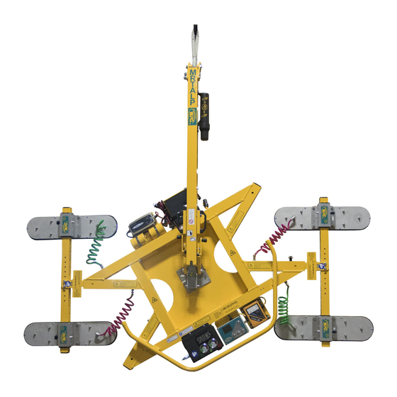
Model numbers: MRTALP4625DC3 (shown),
MRTALP410TDC3
Record serial number in blank space above (to locate, see serial
Rev 6.0/12-19
label on the product).
1
908 W. Main • P.O. Box 368
Laurel, MT USA 59044
800-548-7341 (phone)
406-628-8231 (phone)
406-628-8354 (fax)
www.WPG.com
MRTALP4-DC3: #35058
Advertisement
Table of Contents

Subscribe to Our Youtube Channel
Related Manuals for WPG MRTALP4625DC3


Summary of Contents for WPG MRTALP4625DC3
- Page 1 /TILTER 600, DC-VOLTAGE, WITH INTELLI-GRIP® TECHNOLOGY & PAD FRAME T-ARM ASSEMBLIES Available with REMOTE CONTROL SYSTEM Model numbers: MRTALP4625DC3 (shown), MRTALP410TDC3 Record serial number in blank space above (to locate, see serial Rev 6.0/12-19 MRTALP4-DC3: #35058 label on the product).
- Page 2 MRTALP4-DC3: #35058 Rev 6.0/12-19...
-
Page 3: Table Of Contents
TABLE OF CONTENTS SPECIFICATIONS ..................3 SAFETY....................5 OPERATING FEATURES................6 ASSEMBLY....................7 ...........9 SSEMBLE ISASSEMBLE THE RAME Installing/Removing T-Arm Assemblies................9 Installing/Removing Vacuum Pads..................9 Connecting/Disconnecting Vacuum Hoses ...............10 .................11 DJUST THE RAME Repositioning Vacuum Pads....................12 Repositioning T-Arm Cross Members................12 INTENDED USE ..................13 ................13 HARACTERISTICS ................14 PERATING NVIRONMENT... - Page 4 TABLE OF CONTENTS .................24 OTATE THE ..................25 ILT THE ............27 ELEASE THE ADS FROM THE ................28 FTER SING THE IFTER Storing the Lifter .......................28 INSPECTIONS AND TESTS..............30 ................30 NSPECTION CHEDULE ....................31 ESTING Lifter/Load Compatibility Test...................31 Operational Tests ......................32 Vacuum Test........................32 Rated Load Test.........................33 Remote Control System Test .....................33 MAINTENANCE ..................34...
-
Page 5: Specifications
Designed for use with hoisting equipment, MRTALP4-DC3 lifters support loads using vacuum and Product Description manipulate loads using manual 180° rotation and mechanically assisted, manual 90° tilt motions. Model MRTALP4625DC3 MRTALP410TDC3 Number Vacuum Pads 6" x 25" [15 cm x 64 cm] nominal dimensions, 10"... - Page 6 SPECIFICATIONS Note: Standard MRTALP410TDC3 (top) and MRTALP4625DC3 models are shown. MRTALP4-DC3: #35058 Rev 6.0/12-19...
-
Page 7: Safety
SAFETY Wear personal protective Make sure the contact surfaces of equipment that is appropriate for the load and vacuum pads are clean the load material. Follow trade before attaching the lifter (see association guidelines. “MAINTENANCE”). Do not remove or obscure safety Position the vacuum pads correctly labels. -
Page 8: Operating Features
26 “ATTACH” BUTTON 27 “RELEASE” BUTTON 28 “POWER” BUTTON Note: A standard MRTALP4625DC3 is shown. Although some of the following photos do not show this specific lifter, they all illustrate how this kind of lifter functions. MRTALP4-DC3: #35058 Rev 6.0/12-19... -
Page 9: Assembly
ASSEMBLY 1) Remove all vacuum lifter restraints and save them with the shipping container for future use. If necessary, assemble the lift bar (item 1 in fig. 2A). Tighten bolts (item 2 in fig. 2A) securely. 3) Adjust the lift point to optimize the lifter's hang angle: 3.1) Remove the retaining bolt (item 3 in fig. - Page 10 ASSEMBLY Make sure hook has restraining latch (circled). 4.3) Attach the hoisting hook to the lift Only use rigging rated for Maximum point (fig. 4D-E). Load Capacity plus Lifter Weight. Note: Use rigging (fig. 4F) as needed to make sure the hook does not interfere with the load. 4.4) Use the hoisting equipment to remove the lifter from the shipping container.
-
Page 11: T O Assemble /Disassemble The Pad Frame
ASSEMBLY SSEMBLE ISASSEMBLE THE RAME Installing/Removing T-Arm Assemblies Insert a T-arm assembly into the pad frame (fig. 1A). 2) Use a cotterless hitch pin to secure the T-arm (fig. 2A). 3) Install the second T-arm assembly likewise. Note: Always position T-arms as shown in “OPERATING FEATURES” on page 6. To remove the T-arm assemblies, reverse these steps. -
Page 12: Connecting/Disconnecting Vacuum Hoses
ASSEMBLY Connecting/Disconnecting Vacuum Hoses To connect a vacuum hose, push the male and female ends of Make sure quick the quick connector together until they lock (fig. 1A). connectors seal completely and all vacuum To disconnect a vacuum hose, move the release ring on the hoses function correctly (see female end until the quick connector separates (fig. -
Page 13: T O Adjust The Pad Frame
ASSEMBLY DJUST THE RAME The illustrations above show the range of MRTALP4-DC3 vacuum pad positions available to accommodate different load dimensions and weight distribution. Note: These adjustments do not affect the lifter’s Maximum Load Capacity. Rev 6.0/12-19 MRTALP4-DC3: #35058... -
Page 14: Repositioning Vacuum Pads
ASSEMBLY Repositioning Vacuum Pads Remove the cotterless hitch pin (fig. 1A) that secures a sliding/movable pad mount to the pad frame. 2) Position the pad mount as required on the T-arm assembly. 3) Use the cotterless hitch pin to secure the pad mount. Repeat these steps to position other pad mounts as needed. -
Page 15: Intended Use
1..A “single piece” of material includes curtainwall assemblies, unitized glazing systems and similar construction units. 2..Vacuum pads made from a heat-resistant rubber compound can enable you to lift loads with higher surface temperatures. Contact WPG or an authorized dealer for more information. -
Page 16: Operating Environment
1..Although lifter use may be possible at higher elevations, lifting capacity is reduced whenever the lifter is unable to attain vacuum in the green range on the vacuum gauges. Contact WPG for more information. 2..Special provisions may allow the lifter to operate outside the specified temperature range. Contact WPG for more information. MRTALP4-DC3: #35058... -
Page 17: Operation
OPERATION EFORE SING THE IFTER Determine whether the vacuum lifter is capable of each intended task (see “SPECIFICATIONS” on page 3 and “INTENDED USE” on page 13). Then complete the following preparations: Taking Safety Precautions • Be trained in all industry and regulatory Read all directions and safety standards for lifter operation in your region. -
Page 18: Performing Inspections And Tests
OPERATION Performing Inspections and Tests • Follow the “I ” on page 30 and “T ” on page 31. NSPECTION CHEDULE ESTING • Service the 2 air filters whenever a bowl contains Examine air filters regularly liquid or other contaminates, or an element and service when needed. -
Page 19: Preparing To Use The Remote Control System
OPERATION Preparing to Use the Remote Control System The optional radio transmitter (fig. 1A) and radio receiver enable you to activate the lifter's “attach” and “release” functions at distances up to 250' [76 m], provided you have a clear and direct view of the lifter and its status indicators. -
Page 20: T O Attach The Pads To A Load
OPERATION TTACH THE ADS TO A Make sure that the contact surfaces of the load and the vacuum pads are clean (see “Pad Cleaning” on page 35). Positioning the Lifter on the Load Attach lifter to load as directed below. Failure to follow instructions could result in load damage or personal injury. -
Page 21: Powering Up The Lifter
OPERATION Powering up the Lifter Press the lifter's power button , fig. 1A). The vacuum pump will run for a few seconds, as a normal function ® of the Intelli-Grip self- diagnostics. The lifter automatically tests the 9-volt battery for the notification buzzer each time the lifter is powered up. -
Page 22: Reading The Vacuum Gauges
1..The gauge face colors do not correspond with the circuit colors. 2..If the lifter is used above the maximum Operating Elevation (see “SPECIFICATIONS” on page 3), it may not be able to maintain sufficient vacuum for lifting. Contact WPG for more information. MRTALP4-DC3: #35058... -
Page 23: T O Lift And Move The Load
OPERATION IFT AND OVE THE Lift bar must be vertical to lift load. About the Tilt Linkage The tilt linkage minimizes operator effort and Unbalanced loads may tilt automatically holds a balanced load in either unexpectedly during lifter operation. the upright or the flat position. However, an Make sure load is positioned unbalanced load may tilt unexpectedly, correctly on lifter. -
Page 24: Interpreting The Lift Light
OPERATION Interpreting the Lift Light When the vacuum lifter is ready to lift the Never lift load unless Maximum Load Capacity, the vacuum lift lift light is illuminated, light turns on automatically and the vacuum because premature lifting pump turns off temporarily, to conserve battery could result in load release and personal injury. -
Page 25: Controlling The Lifter And Load
OPERATION Controlling the Lifter and Load When the lifter is ready, use the hoisting equipment to raise the lifter and load as needed. Use a control handle (circled in fig. 1A) to keep the lifter and load in the required position. Once there is enough clearance, you may move the load as required. -
Page 26: T O Rotate The Load
OPERATION OTATE THE Make sure load is positioned correctly on lifter (as previously directed). Never disengage rotation and tilt latches at the same time, because this could result in load damage or personal injury. Never rotate load when lifter is attached “above center” (see “T TTACH THE ADS TO ”... -
Page 27: T O Tilt The Load
OPERATION ILT THE Make sure load is positioned correctly on lifter (as previously directed). Never disengage tilt and rotation latches at the same time, because this could result in load damage or personal injury. Make sure the load has enough clearance to tilt without contacting anyone or anything. - Page 28 OPERATION A load with overhang may force you to release the handle as the load approaches the flat position. In this case, use hand cups (circled in fig. 1A) or other appropriate means to control the load. Note: The pad frame automatically latches when tilted to the vertical position.
-
Page 29: T O Release The Pads From The Load
OPERATION ELEASE THE ADS FROM THE Make sure load is at rest and fully supported before releasing vacuum pads. Hold the “function” button ( fig. 1A) and the “release” button , fig. 1A). If the vacuum seal does not break, follow the directions on the LCD screen. -
Page 30: After Using The Lifter
OPERATION FTER SING THE IFTER Press the power button ( , fig. 1A) and the “function” button ( , fig. 1A) to power down the vacuum lifter. 2) Charge the battery after each workday as needed (see “12-V ATTERY ” on page 36). ECHARGE 3) Use the hoisting equipment to lower the lifter gently onto a stable support. - Page 31 OPERATION Disconnect the electrical connectors (figs. 3A-B and figs. 3C-E) to prevent battery discharge. 4) Store the lifter in a clean, dry location. Store the battery between 32° and 70° F [0° — 21° C]. Avoid storage above 100° F [38° C]. Rev 6.0/12-19 MRTALP4-DC3: #35058...
-
Page 32: Inspections And Tests
2..The Periodic Inspection is also required whenever the lifter has been out of service for 1 year or more. Keep a written record of all Periodic Inspections. If necessary, return the lifter to WPG or an authorized dealer for repair (see “LIMITED WARRANTY” on page 44). -
Page 33: Testing
12" Hg [-41 kPa] for 5 minutes. If not, lifting this load requires additional precautions (eg, a load sling). Contact WPG for more information. 8) Lower the load after 5 minutes or before the vacuum level diminishes to 12" Hg [-41 kPa]. -
Page 34: Operational Tests
2..During this time, the LCD screen displays “WARNING: Is load attached?”, the notification buzzer chirps and the strobe light flashes. 3..For more information, search for your lifter’s Model Number on www.WPG.com and selecting the “Troubleshooting” link on the product page. -
Page 35: Rated Load Test
Remote Control System. 1..An equivalent simulation may also be used. Contact WPG for more information. 2..A “qualified person” has successfully demonstrated the ability to solve problems relating to the subject matter and work, either by possessing a recognized degree in an applicable field or a certificate of professional standing, or by possessing extensive knowledge, training and experience. -
Page 36: Maintenance
NSERTS IN sealing and “T VPFS10T P ” on page 41). EPLACE EALING ING IN edges. 1..Flat Lifters are exempt from this requirement. 2..If necessary, contact WPG for help in conducting a friction test. MRTALP4-DC3: #35058 Rev 6.0/12-19... -
Page 37: Pad Cleaning
6) Power up the lifter again, to test the new battery. 1..A brush with bristles that do not harm rubber can help remove contaminates clinging to sealing edges. If these cleaning methods are not successful, contact WPG or an authorized dealer for assistance. Rev 6.0/12-19... -
Page 38: 12-Volt Battery Recharge
The red error light can indicate other problems, depending on the mode selected and level of charging; if necessary, contact WPG for assistance. 5..The charger automatically reduces the charging rate when the battery is fully charged. -
Page 39: Intelli -Grip ® Diagnostic Codes
Service tool is connected. Remove it before resuming lifter “Firmware updater detected (#)” (none) (none) use and contact WPG. Make sure lifter is used within Operating Temperatures “Module revision not 1 chirp every (see “SPECIFICATIONS” on page 3). Then power lifter (none) compatible”... - Page 40 MAINTENANCE Strobe Buzzer Code On-Screen Message Light Explanations/Directions Pattern Activity continuous Once “Power Save” mode is activated, “attach” and “Module revision lockout” (while button (none) “release” functions are prevented in connection with Code is held) C04. Service is required. “Control head revision not 1 chirp every Incompatible version of software was installed or control (none)
- Page 41 MAINTENANCE Strobe Buzzer Code On-Screen Message Light Explanations/Directions Pattern Activity Fault is detected in hardware that enables communication (none) “App-support hardware fault” (none) with mobile app. Power lifter down and up again. If code persists, service is required. Attempt was made to power down lifter while load was “WARNING! Is load attached?”...
- Page 42 2 seconds system. See relevant topics in “ASSEMBLY,” “OPERATION”, “INSPECTIONS AND TESTS”, and/or “MAINTENANCE”. In case of high elevation, contact WPG for directions. Once “Power Save” mode is activated, “attach” and “release” functions are prevented due to a vacuum sensor V040 “Lockout (vacuum sensor error)”...
-
Page 43: T O Replace Sealing Ring In Vpfs10T Pads
MAINTENANCE VPFS10T P EPLACE EALING ING IN If the lifter has VPFS10T vacuum pads, replace sealing rings as shown: 1) Remove the old sealing ring (fig. 1A). Note: Make sure the entire vacuum pad is clean, including the mounting groove. 2) Place the inside edge of a new sealing ring against the inside edge of the... -
Page 44: Eplace Ad Nserts In Vpfs625 Pads
MAINTENANCE VPFS625 P EPLACE NSERTS IN If the lifter has VPFS625 vacuum pads, replace pad inserts as follows: 1) Remove the lock nuts and washers that secure the top plate to the face plate of the pad assembly (fig. 1A). 2) Remove the top plate (fig. -
Page 45: Replacement Parts
Shoulder Bolt – Socket Head – 5/16" x 1/2" x 1/4-20 Thread (for mounting VPFS10T pads) * Length as required; vacuum hose is sold by the foot (approx. 30.5 cm). See SERVICE MANUAL #36105 for additional parts. ERVICE ONLY WITH IDENTICAL REPLACEMENT PARTS WPG.COM AVAILABLE AT OR THROUGH AN AUTHORIZED DEALER Rev 6.0/12-19... -
Page 46: Limited Warranty
Contact the WPG Technical Service Department. When factory service is required, ship the complete product – prepaid – along with your name, address and phone number to the street address listed at the bottom of this page. WPG may be reached by phone or fax numbers listed below. - Page 47 Rev 6.0/12-19 MRTALP4-DC3: #35058...
- Page 48 MRTALP4-DC3: #35058 Rev 6.0/12-19...
Need help?
Do you have a question about the MRTALP4625DC3 and is the answer not in the manual?
Questions and answers