
Related Manuals for Optika Italy INSPECTION SYSTEMS Series


Summary of Contents for Optika Italy INSPECTION SYSTEMS Series
- Page 1 INSPECTION SYSTEMS Series INSTRUCTION MANUAL Model IS-02 IS-03 Version: 1 Issued: 1.0.0...
-
Page 2: Table Of Contents
SUMMARY Warning Intended use Package Contents Overview Assembly 6. Using the system 6.1 Using the base (IS-02) 6.2 Using the base (IS-03) 6.3 Using the camera (C-HAF) Equipment disposal... -
Page 3: Warning
1. Warning This microscope is a scientific precision instrument designed to last for many years with a minimum of maintenance. It is built to high optical and mechanical standards and to withstand daily use. We remind you that this manual contains important information on safety and maintenance, and that it must therefore be made accessible to the instrument users. -
Page 4: Overview
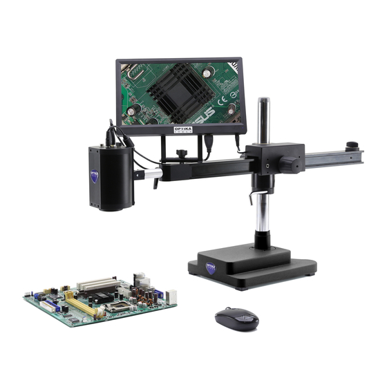
4. Overview (IS-02) HORIZONTAL 11,6” HDMI ARM SLIDING MONITOR FIXING KNOB HORIZONTAL STOPPER AUTOFOCUS CAMERA DROP PREVENTION RING FIXING SCREW BASE (IS-03) 11,6” HDMI MONITOR AUTOFOCUS CAMERA DROP PREVENTION RING DESKTOP CLAMP... - Page 5 (IS-03)
- Page 6 (C-HAF) ON/OFF LED HDMI CABLE SOCKET USB MOUSE SOCKET ON/OFF BUTTON EXTERNAL TRIGGER POWER SUPPLY SOCKET SOCKET 16GB TF CARD SLOT...
- Page 7 5. Assembly (IS-02) Screw the pillar on the base (Fig. 1) Tighten the screw to lock the pillar (Fig. 2) Insert the drop preventing ring. (Fig. 3) Insert the horizontal arm and lock it with the locking knob (Fig. 4 & 5) Fig.
- Page 8 round part) ① (Fig. 7) in the hole at the end of ① Insert the back part of the camera holder (black the horizontal arm and tighten the knob ②. (Fig. 8). ② Fig. 7 Install the HDMI monitor using the provided bracket and the provided screws.
- Page 9 5. Assembly (IS-03) Mount the camera on to the arm, using the provided screws and allen wrench. (Fig. 11) Fig. 11 Install the HDMI monitor on to the arm using the provided screws and allen wrench. (Fig. 12) Fig. 12 Connect HDMI cable from camera to monitor, insert SD card into the camera slot, connect USB mouse then plug the power supplies...
- Page 10 Desk installation Adjust the height of the Desk Clamp ② to suit desktop surface. (Fig. 15) Fig. 15 Attach the desk clamp ② on to the edge of the desk in the desired position and with the clamp opening facing towards the edge of desktop. Tighten by hand to ensure that the desk clamp fully clamps to the desktop surface and is secure.
-
Page 11: Using The Base (Is-02)
6.1 Using the base (IS-02) ①. Moving the horizontal arm (Fig. 16). Unlock the knob on the left side of the horizontal am ① Fig. 16 The arm can be extended or shortened according to specific needs. (Fig. 17) Fig. 17 ②... - Page 12 Fig. 20 Tilting the camera (Fig. 21) Slightly loosen the locking screw and tilt the camera to the desired angle, then lock the screw again. Fig. 21 ④ Loosen the horizontal arm fixing knob ④ and rotate the Rotating the horizontal arm (Fig. 22) microscope.
-
Page 13: Using The Base (Is-03)
6.2 Using the base (IS-03) Adjusting the Mount Bracket Resistance Product is brilliantly engineered to control the resistance in the Tilter Mount Bracket to suit swing side to side of 90 degree and tilt forward and backward of 90 degree. It is possible to control the amount of resistance in the Tilter Mount Bracket. -
Page 15: Using The Camera (C-Haf)
6.3 Using the camera (C-HAF) Camera is supplied with an “on screen” menu, which is activated when the mouse cursor is positioned in the upper left corner of the monitor r. Moving the cursor to a different area the menu disappears. - Page 16 1. “Control” Menu The “Control” panel is divided into different sections related to the various camera controls. “Focus” section controls the focusing of the camera. It is possible to work either in autofocus (AF) or manual focus (MF). Clicking on “AF” camera will work in autofocus mode. It will be sufficient to position the subject to be observed in front of the camera lens and the focus will be obtained in less than 1 second.
- Page 17 Clicking on “MF” camera will work in manual focus mode. Activation of the MF button automatically activate the keys “MF+” e “MF-“, with which you can act on focusing the camera without having to act on the mechanical support, simply by using the mouse. Clicking on “Click F”...
- Page 18 “Color” section controls the color rendering of the camera. Activating the “AWB” function uses automatic white balance. Place a blank sheet of paper in front of the camera sensor and click “AWB”. The camera adjusts the colors output from the camera to the color temperature of the scene being shot.
- Page 19 The “Zoom” cursor allows to vary the magnification of the projection to the monitor of the framed object. It is possible to change the zoom factor (optical zoom) from 1x to 14x both by acting on the cursor in the “Control”...
- Page 20 It is possible to capture single images or videos simply by clicking on the “Capture” button for single images or on “Video” for movie sequences of desired length. The “Flip” function flips the framed image vertically, while the “Mirror” function horizontally flips it. This is useful for making what is observed in the camera consistent with the real object.
- Page 21 The “50 / 60Hz” function is used to eliminate flickering of the image due to the power supply frequency. The “Default” key resets all the settings made and restores the factory settings.
- Page 22 2. “Crosshair” Menu Up to 4 sets of horizontal or vertical rows can be superimposed on the monitor. These lines can be placed anywhere on the monitor by simply dragging the cursor relative to the desired line. The lines can be projected with different colors in order to be easily visible on the monitor, depending on the color of the sample in question.
- Page 23 The lines, once traced, can be visible or hidden. Clicking on the “Show / Hide” button opens the context menu with which you can view a “Show” row or hide it “Hide”. The lines, if hidden, will not be deleted from memory but simply will not be visible.
-
Page 24: Equipment Disposal
Equipment disposal Art.13 Dlsg 25 july 2005 N°151. “According to directives 2002/95/EC, 2002/96/EC and 2003/108/EC relating to the reduction in the use of hazardous substances in electrical and electronic equipment and waste disposal.” The basket symbol on equipment or on its box indicates that the product at the end of its useful life should be collected separately from other waste. - Page 25 INSPECTION SYSTEMS Series MANUALE DI ISTRUZIONI Modello IS-02 IS-03 Version: 1 Issued: 1.0.0...
- Page 26 SOMMARIO Avvertenze Utilizzo previsto Contenuto Panoramica Assemblaggio 6. Uso del sistema 6.1 Uso della base (IS-02) 6.2 Uso della base (IS-03) 6.3 Uso della telecamera (C-HAF) Smaltimento...
-
Page 27: Avvertenze
1. Avvertenze Questo microscopio è uno strumento scientifico di alta precisione, progettato per durare a lungo con una mini- ma manutenzione; la realizzazione è secondo i migliori standard ottici e meccanici, per poter essere utilizzato quotidianamente. Vi ricordiamo che questo manuale contiene informazioni importanti per la sicurezza e per la manutenzione dello strumento, e deve quindi essere messo a disposizione di coloro che lo utilizzeranno. -
Page 28: Panoramica
4. Panoramica (IS-02) VITE DI FISSAGGIO BRACCIO MONITOR SCORREVOLE ORIZZONTALE 11,5” HDMI FERMO ORIZZONTALE TELECAMERA AUTOFOCUS ANELLO PREVENZIONEDI SCESA VITE DI FISSAGGIO BASE (IS-03) MONITOR 11,5” HDMI TELECAMERA AUTOFOCUS ANELLO PREVENZIONEDI SCESA SUPPORTO DA TAVOLO... - Page 29 (IS-03)
- Page 30 (C-HAF) LED ON/OFF CONNETTORE CAVO HDMI CONNETTORE MOUSE USB TASTO ON/OFF CONNETTORE TRIGGER CONNETTORE ESTERNO ALIMENTATORE SLOT SCHEDA SD 16GB...
-
Page 31: Assemblaggio
5. Assemblaggio (IS-02) Avvitare la colonna alla base. (Fig. 1) Serrare la vite per fissare la colonna. (Fig. 2) Inserire l’anello di prevenzione discesa. (Fig. 3) Inserire il braccio orizzontale e bloccarlo con la manopola di fissaggio (Fig. 4 & 5) Fig. - Page 32 telecamera (il perno rotondo nero) ① (Fig. 7) nel ① Inserire la parte posteriore del supporto della manopola ②. (Fig. 8). foro al termine del braccio orizzontale e serrare la ② Fig. 7 Installare il monitor HDMI usando il supporto e le viti in dotazione.
- Page 33 5. Assemblaggio (IS-03) Montare la telecamera sul braccio di supporto utilizzando le viti e le chiavi a brugola in dotazione. (Fig. 11) Fig. 11 Installare il monitor HDMI sul braccio utilizzando le viti e le chiavi a brugola in dotazione.(Fig. 12) Fig.
- Page 34 Installazione a tavolo Regolare l’altezza della pinza da tavolo ② in base alla superficie del tavolo. (Fig. 15) Fig. 15 Montare la pinza da tavolo ② al bordo del banco nella posizione desiderata. Per sicurezza tenere con le mani la pinza da tavolo finché non sia completamente chiusa e la tenuta sia sicura. Posizionare l’anello all’altezza desiderata, sarà...
-
Page 35: Uso Della Base (Is-02)
6.1 Uso della base (IS-02) Muovere il braccio orizzontale (Fig. 16). ①. Allentare la vite di blocco posta sul lato sinistro del braccio orizzontale ① Fig. 16 Il braccio può essere allungato o accorciato in funzione delle . (Fig. 17) specifiche esigenze Fig. - Page 36 Fig. 20 (Fig. 21) Inclinare la telecamera Allentare la vite di blocco e inclinare la telecamera nell’angolo desiderato quindi serrare la vite. Fig. 21 ④ Allentare la manopola di fissaggio del braccio orizzontale ④ e Ruotare il braccio orizzontale. (Fig. 22) ruotare il microscopio.
-
Page 37: Uso Della Base (Is-03)
6.2 Uso della base (IS-03) Regolazione della tensione del braccio Questo strumento è stato sviluppato per poter regolare la resistenza all’inclinazione del braccio sia lateralmente sia dall’alto verso il basso, con un’ampiezza massima di movimento di 90 gradi in entrambe le dire- zioni. - Page 38 Lo strumento può salire o scendere come mostrato. Se tende automaticamente a muoversi lateralmente, è possibile sia necessario regolare la tensione dell’articolazione del braccio per permettere al vostro microscopio di ruotare lateralmente. Questo è possibile utilizzando la chiave a brugola 2,5mm in dotazione.
-
Page 39: Uso Della Telecamera (C-Haf)
6.3 Uso della telecamera (C-HAF) La telecamera è dotata di un menù “on screen” che si attiva quando il cursore del mouse viene posizionato nell’angolo in alto a sinistra del monitor. Spostando il cursore in una zona diversa il menù scompare. - Page 40 1. Menu “Control” Il pannello “Control” è diviso in diverse sezioni relative ai vari comandi della telecamera. La sezione “Focus” comanda la messa a fuoco della telecamera. E’ possibile lavorare in autofocus (AF) o in fuoco manuale (MF). Cliccando su “AF” la telecamera lavora in modalità autofocus. Sarà...
- Page 41 Cliccando su “MF” la telecamera lavora in modalità fuoco manuale. L’attivazione del tasto MF attiva in automatico i tasti “MF+” e “MF-“, con i quali è possibile agire sulla messa a fuoco della telecamera senza dover agire sul supporto meccanico, semplicemente utilizzando il mouse. Cliccando su “Click F”...
- Page 42 La sezione “Color” comanda la resa cromatica della telecamera. Attivando la funzione “AWB” si utilizza il bilanciamento del bianco automatico. Posizionare un foglio di carta bianco di fronte al sensore della telecamera e cliccare “AWB”. La telecamera adatta i colori in uscita dalla telecamera alla temperatura di colore della scena ripresa.
- Page 43 Il cursore “Zoom” permette di variare l’ingrandimento della proiezione a monitor dell’oggetto inquadrato. E’ possibile variare il fattore zoom (zoom ottico) da 1x a 14x sia agendo sul cursore nel pannello “Control” sia agendo sulla barra zoom posta in basso a destra del monitor La telecamera consente inoltre di utilizzare un zoom elettronico (da 1x a 6x), attivando il selettore “Ezoom”.
- Page 44 E’ possibile catturare immagini singole o video semplicemente cliccando sul tasto “Capture” per immagini singole o su “Video” per sequenze filmate di lunghezza desiderata. La funzione “Flip” ribalta verticalmente l’immagine inquadrata, mentre la funzione “Mirror” la ribalta orizzontalmente. Questo è utile per rendere coerente quello che si osserva in telecamera rispetto all’oggetto reale. La funzione “HDR”...
- Page 45 La funzione “50/60Hz” viene utilizzata per eliminare l’eventuale sfarfallio dell’immagine dovuto alla frequenza di alimentazione. Il tasto “Default” ripristina tutte le impostazioni di fabbrica.
- Page 46 2. Menu “Crosshair” E’ possibile sovraimporre sul monitor fino a 4 serie di righe orizzontali o verticali. Queste righe possono essere posizionate in qualsiasi punto del monitor semplicemente trascinando il cursore relativo alla riga desiderata. Le righe possono essere proiettate con colori diversi per poter essere facilmente visibili sul monitor, in funzione del colore del campione in esame.
- Page 47 Le righe, una volta tracciate possono essere visibili o nascoste. Cliccando sul tasto “Show / Hide” si apre il menù di contesto con il quale è possibile visualizzare una riga “Show” o nasconderla “Hide”. Le righe, se nascoste, non verranno eliminate dalla memoria ma semplicemente non saranno visibili. Il tasto “Default”...
-
Page 48: Smaltimento
Smaltimento Ai sensi dell’articolo 13 del decreto legislativo 25 luglio 2005 n°151. “Attuazione delle direttive 2002/95/CE, 2002/96/CE e 2003/108/CE, relative alla riduzione dell’uso di sostanze pericolose nelle apparecchiature elettriche ed elettroniche, nonché allo smaltimento dei rifiuti”. Il simbolo del cassonetto riportato sulla apparecchiatura o sulla sua confezione indica che il prodotto alla fine della propria vita utile deve essere raccolto separatamente degli altri rifiuti. - Page 52 OPTIKA S.r.l. Via Rigla, 30 - 24010 Ponteranica (BG) - ITALIA Tel.: +39 035.571.392 - Fax: +39 035.571.435 mailto:minfo@optikamicroscopes.com www.optikamicroscopes.com...
Need help?
Do you have a question about the INSPECTION SYSTEMS Series and is the answer not in the manual?
Questions and answers