
Subscribe to Our Youtube Channel
Related Manuals for Car Solutions RGB-LE-V3.1


Summary of Contents for Car Solutions RGB-LE-V3.1
- Page 1 Updated date : 2014.02.04 Model : RGB-LE-V3.1 / Product code : RB-100126-013 W164+RGB-LE Specification & Installation Your best partner for better driving...
-
Page 2: Table Of Contents
Contents 1. Before installation 1.1 Main specification 1.2 System diagram 1.3 Components 1.4 Exterior 2. Setup 2.1 DIP switch 2.2 Remote controller 2.3 Power cable wiring diagram 3. Installation 3.1 Installation diagram 3.2 Cautions on installation 4. Troubleshooting... -
Page 3: Main Specification
1.1 Main Specification 1. Input Spec. (MULTI VIDEO INTERFACE) -. 2 x CVBS Input (External video source). -. 1 x CVBS (REAR CAMERA) Input (Rear camera source) -. 1 x Analog RGB Input (Car commander original monitor output) -. 1 x Analog RGB Input (Navigation System output)-OPTION 2. -
Page 4: System Diagram
1.2 System Diagram Remote Control Switch for source toggle & REAR SENSE Navigation Input (Analog RGB) DISPLAY CAR Installation OEM LCD CVBS 1 CVBS 2 VIDEO CIRCUIT CVBS VIDEO MUX (Rear Camera) POWER CIRCUIT CAR SCREEN INPUT HEADREST CVBS (CAR MAIN BOARD) MONITOR DIP S/W Power Input... -
Page 5: Components
1.3 Components SEL cable * 1ea (HSELCA0001) RGB NAVI cable * 1ea (HNAVIC0002) GROUND cable * 1ea (HGROUN0001) Sub-board * 1ea (QCPASS0061) REMOTE CONTROL * 1ea (REMOTE0001) FPC cable * 1ea (FPCABL0007) ORANGE cable * 1ea (HNAVIC0003) IR cable * 1ea POWER cable * 1ea MODE cable * 1ea (HPOWER0001) -
Page 6: Exterior
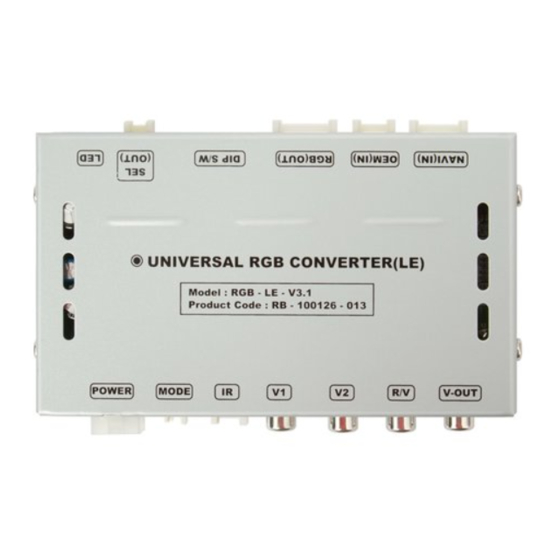
1.4 Exterior ⑬ ⑫ ⑪ ⑩ ⑨ ⑧ Dimension Horizontal length 129mm Vertical length 75mm Height 21mm ⑬ ⑫ ⑪ ⑩ ⑨ ⑧ ① POWER ② MODE ③ IR ④ V1 ⑤ V2 ⑥ R/V ⑦ V-OUT ⑧ NAVI (IN) ⑨... -
Page 7: Dip Switch
2.1 DIP switch ※DIP S/W Use Example #PIN Function DIP S/W selection ON : Skipping RGB Mode [W211] RGB INPUT skip OFF : RGB Display -. Use Input Mode : CVBS1, Navigation (RGB), Main ON : Skipping CVBS1 -. Rear Camera : When to be installed on CVBS 4 CVBS1 MUTE OFF : CVBS1 Display ▷... -
Page 8: Remote Controller
2.2 Remote controller Function POWER & PIP Not for use MENU OSD implementation Making a selection ▲ Move upward ▼ Move downward Move leftward, press 2 seconds long-Factory ◀ mode implementation Move rightward, press 2 seconds long-Factory ▶ Mode implementation-Factory mode Reset SIZE : 85 * 40 * 8 (mm) -
Page 9: Power Cable Wiring Diagram
2.3 Power cable wiring diagram ⑥ ⑤ ④ FILTER & FUSE BOX ③ ② ① ① GND (black) ② I-Drive (orange) ③ FMTX antenna ④ N.C ⑤ ACC(red) ⑥ REAR(gray) Blue FMTX Orange I - DRV Gray Black Blue 990mm Orange Black Grey... -
Page 10: Installation
Cautions on installation Ignition key should be taken off before starting installation, interface power connection must be the last step in installation. Power cable should be separated when connecting interface. Should be no any electronic devices or magnetic pole around installation place. ... -
Page 11: Installation Diagram
Installation diagram ※ Please make sure that the installation MONITOR should be carefully conducted to avoid from the damage of a monitor by SUB-BOARD ESD(Electrostatic discharge) and B G R misalignment while R G B connecting the module of a monitor with cables. -
Page 12: Troubleshooting
Troubleshooting Q. I can not switch A/V sources. A. Check IR or Ground cable connection. Check LED lamps in the interface, if it is not on, check power cable. Q. All I got on the screen is black. A. Check second LED lamp of the interface is on, if not, check A/V sources connected are working well. (Second lamp indicates AV sources connected works well.) Check interface connection has been done well.
Need help?
Do you have a question about the RGB-LE-V3.1 and is the answer not in the manual?
Questions and answers