Table of Contents
Advertisement
Quick Links
For replacement parts visit
WENPRODUCTS.COM
Your new tool has been engineered and manufactured to WEN's highest standards for dependability, ease
of operation, and operator safety. When properly cared for, this product will supply you years of rugged,
trouble-free performance. Pay close attention to the rules for safe operation, warnings, and cautions. If
you use your tool properly and for its intended purpose, you will enjoy years of safe, reliable service.
NOTICE: Please refer to wenproducts.com for the most up-to-date instruction manual.
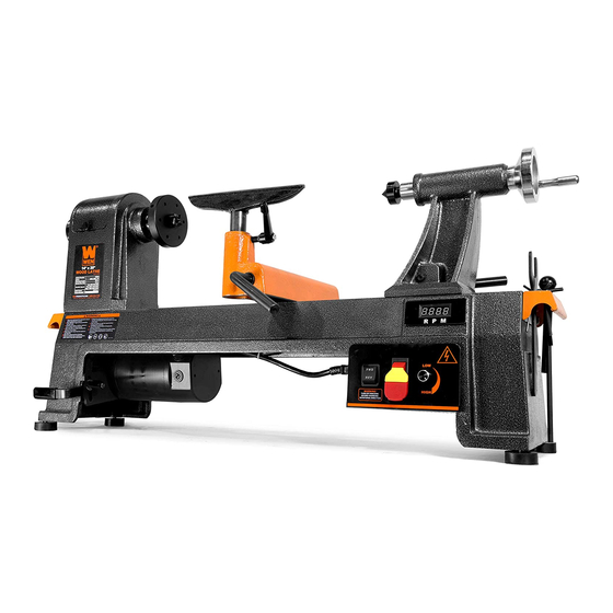
VARIABLE SPEED
WOOD LATHE
IMPORTANT:
NEED HELP? CONTACT US!
Have product questions? Need technical support?
Please feel free to contact us at:
800-232-1195
techsupport@wenproducts.com
WENPRODUCTS.COM
14" x 20"
Model # 34034
bit.ly/wenvideo
(M-F 8AM-5PM CST)
Advertisement
Table of Contents

Subscribe to Our Youtube Channel
Related Manuals for Wen 34034


Summary of Contents for Wen 34034
- Page 1 WENPRODUCTS.COM IMPORTANT: Your new tool has been engineered and manufactured to WEN’s highest standards for dependability, ease of operation, and operator safety. When properly cared for, this product will supply you years of rugged, trouble-free performance. Pay close attention to the rules for safe operation, warnings, and cautions. If you use your tool properly and for its intended purpose, you will enjoy years of safe, reliable service.
-
Page 2: Table Of Contents
Assembly & Adjustments Operation Maintenance Exploded View & Parts List Troubleshooting Warranty Statement PRODUCT SPECIFICATIONS Model Number: 34034 Motor: 120V, 60 Hz, 6A Swing Over Bed: 14 in. (355 mm) Distance Between Centers: 20 in. (510 mm) Center Height: 7 in. (178 mm) -
Page 3: Safety Introduction
SAFETY INTRODUCTION Thanks for purchasing the WEN Lathe. We know you are excited to put your tool to work, but first, please take a moment to read through the manual. This manual provides information regarding potential safety concerns, as well as helpful assembly and operating instructions. Safe operation of this tool requires that you read and under- stand this operator’s manual and all labels affixed to the tool. -
Page 4: General Safety Rules
GENERAL SAFETY RULES WARNING! Read all safety warnings and instructions. Failure to follow all instructions may result in electric shock, fire and serious injury. The term “power tool” in the warnings refers to your mains- operated (corded) power tool. Save all warnings and instructions for future reference. WORK AREA SAFETY 1. - Page 5 GENERAL SAFETY RULES 6. Dress properly. Do not wear loose clothing or jewelry. Keep your hair, clothing and gloves away from moving parts. Loose clothes, jewelry or long hair can be caught in moving parts. 7. If devices are provided for the connection of dust extraction and collection facilities, ensure these are connected and properly used.
-
Page 6: Specific Rules For Wood Lathes
SPECIFIC RULES FOR WOOD LATHES 1. This lathe is designed and intended for use by properly trained and experienced personnel only. If you are not familiar with the proper and safe operation of a lathe, do not use it until proper training and knowledge have been acquired. -
Page 7: Electrical Information
ELECTRICAL INFORMATION GROUNDING INSTRUCTIONS In the event of a malfunction or breakdown, grounding provides the path of least resistance for an electric current and reduces the risk of electric shock. This tool is equipped with an electric cord that has an equipment grounding conductor and a grounding plug. -
Page 8: Know Your Wood Lathe
KNOW YOUR WOOD LATHE Carefully remove the tool and all contents from the packaging. Check all components and compare against the dia- gram below. If any part is damaged or missing, please contact our customer service at (800) 232-1195, M-F 8-5 CST or email us at techsupport@wenproducts.com. -
Page 9: Assembly & Adjustments
ASSEMBLY & ADJUSTMENTS WARNING: To prevent injury from accidental operation, make sure the tool is switched OFF and un- plugged from the power source before assembling or making any adjustments. CLEANING THE MACHINE Your tool comes protected with a layer of anti-rust coating. Wipe off the coating using an acetone-moistened cloth. - Page 10 ASSEMBLY & ADJUSTMENTS SETTING UP THE FACE PLATE (Fig. 3 & 4) NOTE: When installing the face plate for turning bowls and plates, mount the workpiece onto the face plate prior to installing the face plate on the headstock (see page 18). To install the face plate: 1.
- Page 11 ASSEMBLY & ADJUSTMENTS TAILSTOCK ADJUSTMENTS (Fig. 7) Loosen the tailstock locking lever (Fig. 7 - 1) and slide the tail- stock along the lathe bed into the desired position. Retighten the locking lever. Loosen the quill locking handle (Fig. 7 - 2) just enough to unlock the tailstock quill.
- Page 12 ASSEMBLY & ADJUSTMENTS ADJUSTING THE SPEED (Fig. 11 - 14) Your variable speed lathe has three speed ranges: Low 250-720 RPM, Medium 600-1700 RPM, and High 1200-3550 RPM. Al- ways start at slower speeds for rough cuts and larger workpieces. Use faster speeds for refined cuts and detailed work.
-
Page 13: Operation
OPERATION TURNING TOOLS If possible, select only quality high-speed steel turning tools. High-speed steel tools hold an edge and last longer than ordinary carbon steel. As one becomes proficient in turning, a variety of specialty tools for specific applica- tions can be acquired. The following tools provide the basics for most woodturning projects. 2. - Page 14 OPERATION - SPINDLE TURNING WARNING: To prevent serious injury, make sure all the warnings and instructions have been read and understood before operating this tool. MOUNTING THE WORKPIECE BETWEEN SPINDLES (Fig. 16 & 17) Spindle turning takes place between the centers of the lathe, with the workpiece being held between the spur center in the headstock and the live center in the tailstock.
- Page 15 OPERATION - SPINDLE TURNING The following operation instructions serves as a beginning point for some common lathe operations. Practice on scrap material to become familiarized with the operation process and make the necessary adjustments before working on your workpiece. ROUGHING OUT CUT Roughing out is the first step of the lathe operation, which uses the large roughing gouge tool to smooth out sharp corners to make the workpiece cylindrical.
- Page 16 OPERATION - SPINDLE TURNING CREATING BEADS Making a parting cut for the desired depth and location of your bead. 1. Place the parting tool on the tool rest and move the tool forward to make the full bevel of the tool come into contact with the workpiece.
- Page 17 OPERATION - SPINDLE TURNING SANDING THE WORKPIECE Adjust the lathe to a slower speed for sanding and finishing. High speed can build friction while sanding and cause burns in some woods. The cleaner the cuts, the less sanding will be required. So try to make the cuts as refined as you can before moving to the sanding process.
- Page 18 OPERATION - BOWL TURNING MOUNTING THE WORKPIECE ONTO THE FACE PLATE When turning bowls or plates with a large diameter, mounting it to the face plate to gives the maximum amount of support. While face plates are the most reliable method for holding a larger block of wood for turning, a lathe chucks can also be used.
-
Page 19: Maintenance
MAINTENANCE WARNING: Disconnect the machine from the power source before making any maintenance or adjust- ments. Failure to do so may result in serious injury. GENERAL MAINTENANCE 1. Keep your machine clean. Wood contains moisture, meaning that sawdust and wood chips can cause rust if not removed. -
Page 20: Exploded View & Parts List
EXPLODED VIEW & PARTS LIST... - Page 21 EXPLODED VIEW & PARTS LIST Part No. Description Part No. Description 34034-001 Foot 34034-046 Handwheel Handle Belt Tension Lock Lever, 34034-047 Set Screw 34034-003 M8X20 34034-048 Tailstock Lock Lever 34034-004 Washer 34034-050 Tailstock Clamp Bolt 34034-006 Head Cap Screw, M6X16...
-
Page 22: Troubleshooting
Improper tool being used. Use correct tool for operation. Lock nut (34034-052) needs adjusting. Tighten cam lock nut. Tailstock moves when Remove the tailstock and clean the surfaces locked and pressure is Lathe bed and tailstock mating surfaces with a cleaner. - Page 23 LIMITED TWO YEAR WARRANTY WEN Products is committed to build tools that are dependable for years. Our warranties are consistent with this commitment and our dedication to quality. LIMITED WARRANTY OF WEN CONSUMER POWER TOOLS PRODUCTS FOR HOME USE GREAT LAKES TECHNOLOGIES, LLC (“Seller”) warrants to the original purchaser only, that all WEN con- sumer power tools will be free from defects in material or workmanship for a period of two (2) years from date of purchase.
- Page 24 THANKS FOR REMEMBERING...
Need help?
Do you have a question about the 34034 and is the answer not in the manual?
Questions and answers