Advertisement
Table of Contents
4005911
For replacement parts visit
WENPRODUCTS.COM
Your new tool has been engineered and manufactured to WEN's highest standards for dependability, ease
of operation, and operator safety. When properly cared for, this product will supply you years of rugged,
trouble-free performance. Pay close attention to the rules for safe operation, warnings, and cautions. If
you use your tool properly and for its intended purpose, you will enjoy years of safe, reliable service.
NOTICE: Please refer to wenproducts.com for the most up-to-date instruction manual.
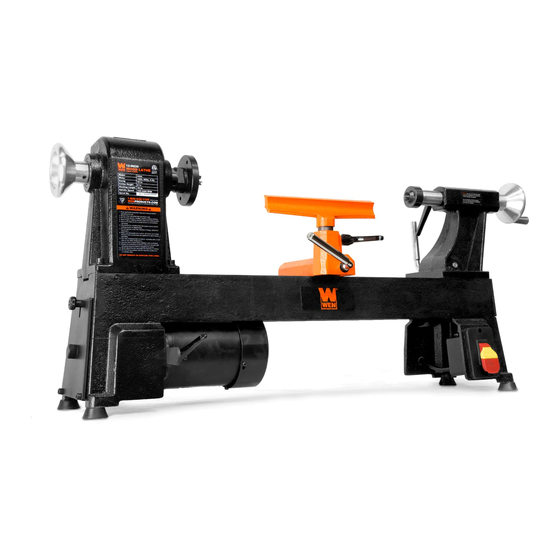
12" x 18" 5-SPEED
WOOD LATHE
IMPORTANT:
NEED HELP? CONTACT US!
Have product questions? Need technical support?
Please feel free to contact us at:
800-232-1195
techsupport@wenproducts.com
WENPRODUCTS.COM
Model # 3424, 3424T
bit.ly/wenvideo
(M-F 8AM-5PM CST)
Advertisement
Table of Contents

Related Manuals for Wen 3424


Summary of Contents for Wen 3424
- Page 1 WENPRODUCTS.COM IMPORTANT: Your new tool has been engineered and manufactured to WEN’s highest standards for dependability, ease of operation, and operator safety. When properly cared for, this product will supply you years of rugged, trouble-free performance. Pay close attention to the rules for safe operation, warnings, and cautions. If you use your tool properly and for its intended purpose, you will enjoy years of safe, reliable service.
-
Page 2: Table Of Contents
Adjustments Operation Maintenance Exploded View & Parts List Troubleshooting Warranty Statement PRODUCT SPECIFICATIONS Model Number: 3424, 3424T Motor: 120 V, 60 Hz, 4.5A Swing Over Bed: 12 in. Distance Between Centers: 18 in. Spindle Speeds: 520, 900, 1400, 2150 and 3400 RPM Spindle Taper: 1"- 8... -
Page 3: Safety Introduction
SAFETY INTRODUCTION Thanks for purchasing the WEN Wood Lathe. We know you are excited to put your tool to work, but first, please take a moment to read through the manual. This manual provides information regarding potential safety concerns, as well as helpful assembly and operating instructions. Safe operation of this tool requires that you read and understand this operator’s manual and all labels affixed to the tool. -
Page 4: General Safety Rules
GENERAL SAFETY RULES WARNING! Read all safety warnings and instructions. Failure to follow all instructions may result in electric shock, fire and serious injury. The term “power tool” in the warnings refers to your mains- operated (corded) power tool. Save all warnings and instructions for future reference. WORK AREA SAFETY 1. - Page 5 GENERAL SAFETY RULES 6. Dress properly. Do not wear loose clothing or jewelry. Keep your hair, clothing and gloves away from moving parts. Loose clothes, jewelry or long hair can be caught in moving parts. 7. If devices are provided for the connection of dust extraction and collection facilities, ensure these are connected and properly used.
-
Page 6: Specific Rules For Wood Lathes
SPECIFIC RULES FOR WOOD LATHES 1. This lathe is designed and intended for use by properly trained and experienced personnel only. If you are not familiar with the proper and safe operation of a lathe, do not use it until proper training and knowledge have been acquired. -
Page 7: Electrical Information
ELECTRICAL INFORMATION GROUNDING INSTRUCTIONS In the event of a malfunction or breakdown, grounding provides the path of least resistance for an electric current and reduces the risk of electric shock. This tool is equipped with an electric cord that has an equipment grounding conductor and a grounding plug. -
Page 8: Know Your Wood Lathe
KNOW YOUR WOOD LATHE Carefully remove the tool and all contents from the packaging. Check all components and compare against the diagram below. If any part is damaged or missing, please contact our customer service at (800) 232-1195, M-F 8-5 CST or email us at techsupport@wenproducts.com. -
Page 9: Assembly
ASSEMBLY WARNING: To prevent injury from accidental operation, make sure the tool is switched OFF and un- plugged from the power source before assembling or making any adjustments. REMOVING THE ANTI-RUST GREASE The lathe bed and centers have been coated with grease to prevent them from rusting. 1. - Page 10 ASSEMBLY INSTALLING THE SPUR CENTER (Fig. D) 1. Make sure the mating surfaces of both the spur center and the headstock spindle are clean. 2. Drive the spur center (Fig. D - 1) into the workpiece (Fig. D - 2) using a rubber mallet or a piece of scrap wood. 3.
- Page 11 ASSEMBLY INSTALLING THE ACCESSORY HOLDER (FIG. H & I) 1. Position the accessory holder (Fig. H - 1) below the headstock on the back of the base. Align the holes and secure the accessory holder using two M5×12 pan head screws (Fig. H - 2). Tighten the screws using the 3mm hex wrench. You can organize your wrench, hex wrenches, knockout rod, live center and spur center into the accessory holder as shown in Fig.
-
Page 12: Adjustments
ADJUSTMENTS TOOL REST ADJUSTMENTS (Fig. K) You can adjust the height, position and angle of the tool rest assembly (Fig. K - 1) to suit your task at hand. To adjust the tool rest: 1. Loosen the small locking handle (Fig. K - 2) to raise and lower the tool rest or to adjust its angle. - Page 13 ADJUSTMENTS SPEED ADJUSTMENTS (Fig. M to P) This lathe has five speeds (520, 900, 1400, 2150 and 3400 RPM) as shown on the speed label (Fig. M). To change the speed: 1. Loosen the back cover knob (Fig. N - 1), then pull up and open the back cover (Fig.
-
Page 14: Operation
OPERATION TURNING TOOLS If possible, select only quality high-speed steel turning tools. High-speed steel tools hold an edge and last longer than ordinary carbon steel. As one becomes proficient in turning, a variety of specialty tools for specific applica- tions can be acquired. The following tools provide the basics for most woodturning projects. 2. - Page 15 OPERATION - SPINDLE TURNING WARNING: To prevent serious injury, make sure all the warnings and instructions have been read and understood before operating this tool. MOUNTING THE WORKPIECE BETWEEN SPINDLES (Fig. Q & R) Spindle turning takes place between the centers of the lathe. It requires a spur center in the headstock and a live center in the tailstock.
- Page 16 OPERATION - SPINDLE TURNING (CONT.) ROUGHING OUT Begin with a large roughing gouge (see page 14 for examples of common cutting tools). 1. Place the tool on the tool rest with the heel of the tool on the surface to be cut. Slowly and gently raise the tool handle until the cutting edge comes into contact with the workpiece.
- Page 17 OPERATION - SPINDLE TURNING (CONT.) CREATING V-GROOVES Using the point of the skew to create a V-groove in the workpiece. 1. Lightly mark the center of the V with the top of the skew. Move the point of the skew to the right half of the desired width of your cut.
- Page 18 OPERATION - BOWL TURNING MOUNTING THE WORKPIECE ONTO THE FACE PLATE The face plate is common for holding a block of wood of a larger diameter for turning bowls and plates. 1. Select a stock that is at least .2 inches (5 mm) larger than each dimension of the finished workpiece. 2.
-
Page 19: Maintenance
OPERATION - BOWL TURNING TO SHAPE THE INSIDE OF THE BOWL Stop the lathe and move the tailstock away. Adjust the tool rest in front of the bowl just below the centerline at a right angle to the lathe’s turning axis. Rotate the workpiece by hand to check for clearance. Start by lightly shearing across the top of the workpiece from rim to center. -
Page 20: Exploded View & Parts List
EXPLODED VIEW & PARTS LIST NOTE: Repairs and replacements should only be performed by an authorized technician. Parts and accessories that wear down over the course of normal use are not covered by the two-year warranty. - Page 21 EXPLODED VIEW & PARTS LIST Part No. Description Qty. Part No. Description Qty. 3424-001 Rear Spindle Wheel 3424-043 Side Cover Locking Knob 3424-002 Set Screw 3424-044 Left Cover 3424-003 Ball Bearing, 6004ZZ 3424-045 M6×16 Screw 3424-004 Retaining Ring 3424-046 Base...
-
Page 22: Troubleshooting
Excessive vibration. Worn spindle bearing. Replace the spindle bearings . Worn drive belt. Replace the drive belt (Part No. 3424-037). Lathe is on an uneven surface. Place the lathe on a flat surface. Dull tools. Use sharp tools. - Page 23 LIMITED TWO YEAR WARRANTY WEN Products is committed to build tools that are dependable for years. Our warranties are consistent with this commitment and our dedication to quality. LIMITED WARRANTY OF WEN CONSUMER POWER TOOLS PRODUCTS FOR HOME USE GREAT LAKES TECHNOLOGIES, LLC (“Seller”) warrants to the original purchaser only, that all WEN con- sumer power tools will be free from defects in material or workmanship for a period of two (2) years from date of purchase.
- Page 24 THANKS FOR REMEMBERING...
Need help?
Do you have a question about the 3424 and is the answer not in the manual?
Questions and answers