Table of Contents
Advertisement
Advertisement
Table of Contents

Subscribe to Our Youtube Channel
Summary of Contents for Cranesmart Systems LMI System
- Page 1 Rev 9 Cranesmart Systems LMI System - User Manual May 11, 2015...
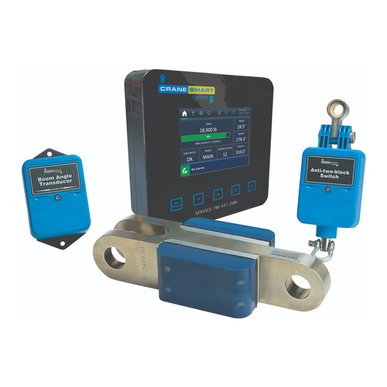
- Page 2 The Cranesmart LMI System ™ Congratulations! “You have invested in the industry’s leading technology in crane safety equipment.” This manual covers the installation and operation of all Cranesmart™ Load Moment Indicators (LMI). For sales, service or assistance: (888) 562-3222 / 1 (780) 437-2986 An electronic copy of this manual is available at www.cranesmart.com...
- Page 3 Warranty Cranesmart™ Systems warrants to the purchaser of each new Cranesmart™ System that any part thereof which proves to be defective in material or workmanship within two (2) years from date of delivery will be repaired or replaced at no charge if the system is returned to us in Edmonton, Alberta with all freight charges prepaid.
- Page 4 Important Safety Information All of Cranesmart™ Systems‟ load cells and support hardware have been designed and tested to have a minimum 5 to 1 safety factor and to meet or exceed the guidelines, standards and certification requirements set forth by more than 30 legislative bodies world-wide including API, ABS, DNV, ASME and OSHA.
-
Page 5: Table Of Contents
Table of Contents INSTALLATION INSTRUCTIONS ............................ 10 LOAD CELL LINK INSTALLATION ..........................11 Male/Female load cell installation (7,500, 15,000 & 25,000 lbs) ................11 Male/Female 7.5/15/25K Load Cell Link Placement Dead-end - for Multiple Parts-of-Line: ......12 Male/Female 7.5/15/25K Load Cell link Placement on Headache Ball - for Single Part-of-Line: ...... 13 Male/Male Flat Link Load Cell Installation (40,000, 50,000 or 80,000 lbs.) ............ - Page 6 RADIO CABLE REEL WITH BOOM ANGLE MEASUREMENT .................. 28 Cable Reel Assembly ..............................28 Cable Reel Installation ..............................29 Installation of Mounting Feet ..........................29 Small Cable Reel Installation ..........................30 Large Cable Reel Installation ..........................31 Cable Reel Drum Installation ..........................31 Installing the Guides and Anchor ..........................
- Page 7 Junction Box Wiring Diagram ..........................44 Alarm Hub .................................. 45 Alarm Hub Wiring Diagram ..........................46 Antenna Installation ..............................47 Antenna types ................................ 47 Outside Operator Cab OR no Cab on Crane ......................48 Inside Operator Cab ............................... 49 Marine Installation ..............................50 Shut-off Bypass Plug ..............................
- Page 8 Tip Height Limits ..............................62 Radius Limits ................................. 62 Level Transducer Limits ............................63 Wind Limits ................................63 System Menu ................................64 About ..................................64 LCD Contrast ................................. 64 Permissions ................................64 Diagnostic Menu ................................. 65 Signals ..................................65 Panel Relay ................................65 Viewer ..................................
- Page 9 BDT Default ................................75 Basket Capacity ..............................76 System Menu ................................76 About ..................................76 LCD Contrast ................................. 76 Permissions ................................77 Restricted ................................77 Clock ..................................77 Checksum Repair ..............................77 Display Timer ................................ 78 Supervisor Enable/Disable Menu ..........................78 Logger Menu ................................
- Page 10 25,000lb single line pull load cell ..........................92 40,000lb single line pull load cell ..........................93 50,000lb single line pull load cell ..........................94 80,000lb single line pull load cell ..........................95 Anti-2-Block Switch ..............................96 Boom Angle Transducer ............................. 97 Display Panel ................................
-
Page 11: Installation Instructions
Installation Instructions Guidelines Read these instructions before beginning installation procedures. If the power available is not 12 to 24VDC (28VDC maximum) Cranesmart™ Systems can supply the necessary converters. Please call our service department at (888) 562-3222 or (780) 437-2986. Have the necessary tools available. ... -
Page 12: Load Cell Link Installation
Load Cell Link Installation: “Male to Female” load cell form (7,500, 15,000 & 25,000 lbs) (Blue = Main Line, Yellow = Aux. 1 Line, Orange = Aux. 2 Line) Refer to the following two illustrations for the correct installation of the load cell(s): 1. -
Page 13: Male/Female 7.5/15/25K Load Cell Link Placement Dead-End - For Multiple Parts-Of-Line
Load Cell Link Installation: “Male to Female” form (Dead-End / Multiple Parts-of-Line) 1. Pin the load cell link between the wire rope (wedge) socket and the dead end as illustrated below. 2. Your system is calibrated at the factory. 3. If you have any questions please call our sales department at (888) 562-3222 or (780) 437-2986. NOTE: ... -
Page 14: Male/Female 7.5/15/25K Load Cell Link Placement On Headache Ball - For Single Part-Of-Line
Male/Female 7.5/15/25K Load Cell link Placement on Headache Ball - for Single Part-of-Line: Pin the load cell link between the wire rope (wedge) socket and the “Headache Ball” or hook block as illustrated below. Your system is factory calibrated. If you have any questions please call our sales department at (888) 562-3222 or (780) 437-2986. -
Page 15: Male/Male Flat Link Load Cell Installation (40,000, 50,000 Or 80,000 Lbs.)
Male/Male Flat Link Load Cell Installation (40,000, 50,000 or 80,000 lbs.) (Blue = Main, Yellow = Aux. 1 Winch, Orange = Aux. 2 Winch) Sandwich Link Stabilization Pin – Male/Male flat link load cells only The Sandwich Link Stabilization Pin prevents the sandwich link from folding against, and damaging the load cell when the headache ball or hook block is laid on the ground or during a two-blocking. -
Page 16: Male - Male 40/50/80K Load Cell Link Placement On Boom Tip Dead-End - For Multiple Parts-Of-Line
Male – Male 40/50/80K Load Cell Link Placement on Boom Tip Dead-end - for Multiple Parts-of-Line: The drawings below show the standard Sandwich Link installation and the optional 24” long Sandwich Link installation. Use the Sandwich Links to pin the load cell link between the wire rope socket (becket) and the dead end boom tip as illustrated below. -
Page 17: Male - Male 40/50/80K Load Cell Link Placement On Headache Ball - For Single Part-Of-Line
Male – Male 40/50/80K Load Cell Link Placement on headache Ball – for Single Part-of-Line: Pin the load cell link between the wire rope (wedge) socket and the “Headache Ball” or hook block as illustrated below. Place the locking threaded centre pin and the stabilization pin as illustrated below. Your system is factory calibrated. -
Page 18: Load Cell Battery Replacement
Load Cell Battery Replacement The display panel will indicate a low battery for approximately three (3) weeks before the battery fails. Starting for systems sold during and after February 2008, Cranesmart™ Systems will supply replacement power cells for our transmitters for the cost of freight shipping (customers are responsible for any incurred taxes/duties). Before replacing the batteries call the service department at (888) 562-3222 or (780) 437-2986. - Page 19 Locate the four exposed hex bolts on the battery compartment side of the Load Cell. If the holes are filled with silicone you are on the transmitter side of the Load Cell. Do not open this side, it has no user serviceable parts. Your warranty will be Void if the Transmitter Electronics section has been opened.
-
Page 20: Radio Linerider Installation
Radio Linerider Installation The linerider installation will depend on the type of boom. Please read and follow the applicable instructions for hydraulic or lattice style booms. Radio Linerider Installation Overview The linerider is attached to a swing arm mounting bracket (included with kit) as shown in the illustration below. The swing arm assembly has four joints: 1. -
Page 21: Hydraulic Boom Linerider Installation Instructions
Hydraulic Boom Linerider Installation Instructions Important note: The linerider component should be located on the top of the boom and as close to the dead end section boom tip as possible – see illustration. Installation steps 1. Affix the bolt at the tip of the base section (dead section) of the hydraulic boom as illustrated to the right. -
Page 22: Lattice Boom Linerider Installation Instructions
Lattice Boom Linerider Installation Instructions Important note: The linerider component should be located on the top of the boom and as close to the boom tip as possible. Installation steps 1. Select a location that the swing arm angle with respect to the boom will not exceed 30° (see figure below). The linerider should be mounted as close to the lattice boom tip as possible. - Page 23 Cranesmart LMI Version R9...
-
Page 24: Installing The Wire Rope (Hoisting Cable) Through Linerider Assembly Instructions
Installing The Wire Rope (Hoisting Cable) Through Linerider Assembly Instructions Important note: The linerider component should be located on the top of the boom and as close to the boom tip as possible. The wire rope should be maintained according to standard practices (in good condition, properly lubricated) to ensure correct calibration. -
Page 25: Anti-2-Block Installation
Anti-2-Block Installation (Blue = Main, Yellow = Aux. 1 Winch, Orange = Aux. 2 Winch) The switch is designed to swivel and pivot so that it is always in an upright vertical position in line with the wire rope, regardless of the boom angle. 1. -
Page 26: Counterweight
NOTE: Ensure the A2B switch can move freely without contacting the boom, the sheaves, bracing struts or any other equipment such as a swing away jib extension. The Eyebolt on the weld bar is used with the red clip for storage and transportation on mobile cranes. When transporting the crane it is advised that the weight is hung using this method. -
Page 27: Boom Angle Transducer Installation
Boom Angle Transducer Installation The Boom Angle transducer must be installed on the boom at a distance of at least five (5) feet from where the antenna will be mounted on the cab of the crane (See page 47) and must maintain line of sight with the antenna in all boom positions. -
Page 28: Wind Speed Transducer Installation
Wind Speed Transducer Installation The wind speed transducer is designed to swivel so that it is always in an upright vertical position, regardless of the boom angle. Tools required 5/16” hex key (included) 3/16” hex key (included) Welder Wind Speed Installation Procedure 1. -
Page 29: Radio Cable Reel With Boom Angle Measurement
Radio Cable Reel with Boom Angle Measurement The Cable Reel measures boom length and boom angle. It is commonly purchased as part of the LMI (Load Moment Indicator) Systems for Hydraulic cranes. The drum is attached to a fixed position on the base boom section of the crane and the end of the cable is anchored to the tip section of the boom. -
Page 30: Cable Reel Installation
Cable Reel Installation The cable reel is set up for use on the left side of the boom but it can be installed on either the left or right side of the boom. The drawing below shows standard left side boom installation with the cable spooling off the drum from the top. If you are mounting the cable reel on the right side of the boom the cable will spool off the drum from the bottom. -
Page 31: Small Cable Reel Installation
Small Cable Reel Installation The Small Cable Reel will arrive from the factory fully assembled and ready to install 1. Lift the Cable Reel assembly on to the mounting feet. 2. Using the supplied hardware bolt the Mounting Plate to the mounting feet. 3. -
Page 32: Large Cable Reel Installation
Large Cable Reel Installation The Large Cable Reel will arrive from the factory partially disassembled. The Drum will be packaged separate from the Cable Reel body assembly and the Cable Reel Transducer will be mounted to a separate Transducer Extension Plate. 1. -
Page 33: Installing The Guides And Anchor
Installing the Guides and Anchor The anchor and guide arms may need to be modified (shortened) to accommodate your installation of the cable reel. 1. The first guide is to be mounted up the boom, 2-4 feet away from the drum. Position it vertically to allow the cable to pass through the guide. It should be horizontally aligned with the middle of the drum in order to allow for proper water run-off. -
Page 34: Terminating The Cable At The Anchor
Terminating the Cable at the Anchor The cable reel anchor design allows the operator to remove the cable from the boom quickly and easily. 1. Slide crimped cable end through the keyhole opening in the anchor. 2. Install the retaining bolt, lock washer and nut to secure the cable in the keyhole opening. NOTE: ... -
Page 35: Level Transducer Installation Instructions
Level Transducer Installation Instructions Installation Type A – Measuring Machine Tilt (Roll) This installation is typically used in marine applications where the crane is on a ship or a barge and it allows the user to observe actual tilt based on the direction of the boom. 1. -
Page 36: Installation Type B - Measuring Grade And Super Elevation / Ship List (Roll) And Trim (Pitch)
Installation Type B – Measuring Grade and Super Elevation / Ship List (Roll) and Trim (Pitch) This installation should be used for Locomotive Cranes (grade and super elevation) or Ship and Barge applications where the user wants the Cranesmart™ system to indicate if the ship is listing (Rolling) or Trimming (pitching) 1. -
Page 37: Level Transducer Error Messages
Level Transducer Error Messages During installation or operation of a system with a Level Transducer installed, the system may give various error messages relating to the Level Transducer. PITCH ROLL ABOVE PRESET MAXIMUM ABOVE PRESET MAXIMUM If a ROLL ABOVE PRESET MAXIMUM message is displayed it means that the Transducer is tilted sideways from its calibrated zero past the number of degrees set in the LIMITS screen. -
Page 38: Battery Replacement For Anti-2-Block, Angle, Cable Reel & Level Transducers
Battery Replacement for Anti-2-Block, Angle, Cable Reel & Level Transducers The display panel will indicate a low battery for approximately three (3) weeks before the battery fails. Before replacing the batteries call the service department at (888) 562-3222 or (780) 437-2986. Once you have verified that it is a dead battery follow the steps below. -
Page 39: Boom Direction Transducer - Bdt
Boom Direction Transducer – BDT The Boom Directional Transducer allows the user to set up lift areas for the crane and can be used to automatically set up load charts based on those lift areas Mounting the BDT Bracket 1. Using the supplied bracket, mount the BDT to the turret. 2. - Page 40 3. Attach each of the corresponding tank tags to the correct location on the turret. Starting at the front (the center of the transducer when the boom is pointing directly forward) and turning clockwise, the number on the tank tags should increase; the first tag will have the lowest number.
-
Page 41: Display Panel Installation
Display Panel Installation Mounting the Display Panel 1. Mount the Display Panel where the operator has an unobstructed view. 2. Remove Bracket from the Display Panel by turning the fluted knob off the bolt and sliding it out. 3. Align, mark and drill mounting holes using the mounting bracket as a guide. 4. -
Page 42: Wiring The Display Panel
Wiring the Display Panel Power to the Display Panel is supplied through the three-conductor cable labelled Power, included in the kit, which plugs into the back of the panel. Refer to the wiring diagram below. 1. Connect the Red wire to a positive 12 or 24 VDC (28VDC Max) terminal. 2. -
Page 43: Basic Wiring Diagram
Basic Wiring Diagram Cranesmart LMI Version R9... -
Page 44: Power Converters
Power Converters A power converter is needed where the only supply is AC voltages. Cranesmart™ power converters change 110/220V AC to 12/24VDC depending on the application. If a power converter is needed it is normally discussed at the time of purchase. -
Page 45: Junction Box Wiring Diagram
Junction Box Wiring Diagram Cranesmart LMI Version R9... -
Page 46: Alarm Hub
Alarm Hub When used with the alarm hub the panel has the ability to control 4 separate outputs. These outputs can be set normally hot or normally cold. The alarms that control the outputs of the alarm hub are specified at the time of purchase. The standard alarm hub comes supplied with the following cables: ... -
Page 47: Alarm Hub Wiring Diagram
Alarm Hub Wiring Diagram Cranesmart LMI Version R9... -
Page 48: Antenna Installation
Antenna Installation There are three types of antennas; installation and placement depend on the length and type of boom on your crane. Antenna types 1. Panel Mount – For all cranes without a cab 2. External Mount – For cranes with cabs 3. -
Page 49: Outside Operator Cab Or No Cab On Crane
Outside Operator Cab OR no Cab on Crane When the display panel is mounted outside of the cab or there is no cab on the crane use the panel mount antenna. This antenna is normally installed at the factory, if it is not installed, do the following: 1. -
Page 50: Inside Operator Cab
Inside Operator Cab When the display panel is mounted inside the cab of the crane use the external magnetic mount antenna. This antenna will be included in the system packaging. Installation varies between cranes but use the following as a guideline. For optimum performance, the antenna should be installed horizontally as shown below but it will work in a vertical orientation also. -
Page 51: Marine Installation
Marine Installation When the Cranesmart™ system is used on a crane with a cab in a marine environment use the external marine antenna included in the kit. Installation varies between cranes but use the following as a guideline. For optimum performance, the antenna should be installed at a 45 angle as shown below. Determine the best position for the antenna;... -
Page 52: Shut-Off Bypass Plug
Shut-off Bypass Plug The bypass plug is only required with systems that are using shut-off functions and only if those solenoids are “Normally Hot” (energized), supplying power while in the normal operational modes (not alarming). If you have installed the system using the white output wire to control your crane shut-offs/kick outs and the Cranesmart™... -
Page 53: Display Panel Operations
System Start-up When the Cranesmart™ LMI System starts it follows a series of steps that enable the operator to accept the current settings and load chart or make any necessary changes. The first screen displayed is the Cranesmart™ systems logo. -
Page 54: To Accept The Current Configuration
To Accept the Current Configuration 1. Select continue. (The Verify Load Chart screen will be displayed). 2. Select continue. The Primary Operating screen will be displayed and the panel will begin operation. To Change the Display Panel Configuration Use the Up or Down arrows, select Change. 2. -
Page 55: Quick Winch Switching
Quick Winch Switching Quick Winch Switching enables operators to quickly change the display to show the auxiliary winch line. NOTE: A winch can only be selected if a load cell is enabled on that winch. To Change or View the Auxiliary Lines EDIT: Condense these two entries Use the Up or Down arrows, select Change. -
Page 56: To View The Auxiliary Winches
To View the Auxiliary Winches 1. Press the Up or Down arrows, (a message is displayed warning the user that the system will change to another winch). 2. Press Accept to Change, (the configuration screen for the new winch will be displayed). 3. -
Page 57: To Accept The New Winch Configuration
To Accept the New Winch Configuration 1. Select continue. (The Verify Load Chart screen will be displayed). 2. Select continue. (The Primary Operating screen will display the new winch selection and the panel will begin operation). Cranesmart LMI Version R9... -
Page 58: Panel Button Functions
Panel Button Functions EDIT: Move this ahead of the winches By-pass The By-pass button enables the operator to by-pass any existing alarms. It enables the operator to override any shut-offs and restore crane functions while the system is in alarm. The Bypass works for 30 seconds and displays the remaining time periodically before returning to normal functioning. -
Page 59: Menu Navigation
Menu Navigation The Cranesmart™ System uses a menu system to lead you through its functions. In normal operating mode the system provides a general level menu of functions for which operators have permission. In supervisor mode the system provides access to enable supervisors to configure a system to match their needs. The Cranesmart™... -
Page 60: Setup Menus
To Disable Tare Out If the system has a Boom Angle Indicator the Tare Out function is automatically disabled when the crane‟s angle is changed by 3. To Disable the Tare Out function for a system without a Boom Angle Transducer use the following steps: 1. -
Page 61: Operator Permission Level
Operator Permission Level Limits Enables users to set limits for Load, Angle, Tip Height, Radius and Wind Speed indicators. Configure Enables users to select the Winch and Parts-of-line to be displayed. System Enables users to display the serial number of the system or change the permission level. Diagnostic Enables users to view the signal strength and RF signal from the transducers. -
Page 62: Configure Menu
Configure Menu The Configure Menu enables users to select the winch in use and set parts-of-line. Select Winch and POL (Parts-of-line) 1. From the Primary Operating screen press select, the Secondary Operating screen is displayed. 2. Use the Up or Down arrows, select Setup. 3. -
Page 63: Angle Limits
Angle Limits 1. From the Primary Operating screen press select, the Secondary Operating screen is displayed. 2. Use the Up or Down arrows, select Setup. 3. Use the Up or Down arrows, select Limits. 4. Use the Up or Down arrows, select Angle, you will be defaulted to Max. 5. -
Page 64: Level Transducer Limits
3. Use the Up or Down arrows, select Limits. 4. Use the Up or Down arrows, select Radius, you will be defaulted to the Max of the Main Radius. 5. Select Max. 6. Use the Up or Down arrows, set Maximum Radius. 7. -
Page 65: System Menu
5. Select MAX WIND. 6. Use the Up or Down arrows to increase or decrease the maximum wind speed. Minimum wind speed setting is defaulted at 15 MPH and can not be set to a lesser value. 7. Press ACCEPT twice to save. System Menu The system menu provides information about the system on the crane and enables users to set Access Permissions. -
Page 66: Diagnostic Menu
5. Press select on Permission. 6. Use the Up or Down arrows, set the Permission Access Code. 7. Press Accept twice to save. 8. Use the Up or Down arrows to select Top Menu to continue with changed permission or, Select Exit to return to Primary Operating Screen and Operator Permission level. -
Page 67: Cable Reel
6. Load Cal will allow the user to view the calibration information of the load transducer. No adjustments can be made from this screen. 7. IDs will allow the user to see the ID numbers for each component possible on the system. No adjustments can be made from this screen. 8. -
Page 68: Supervisor Permission Level
Supervisor Permission Level Configure Enables users to select the Winch and Parts-of-line to be displayed. Limits Enables users to set limits for Load and Angle indicators. (Not in A2B only systems) Calibrate Enables supervisors to set calibrations for the Load, Angle, Level or Cable Reel. Options Enables supervisors to Enable or Disable the Limits Lock, Bypass button or External Alarms. -
Page 69: Permissions Level
Permissions Level To access these menu selections you must use the Supervisor Permission code of “111” at the permission screen To Set the Permission Level 1. From the Primary Operating screen press select, the Secondary Operating screen is displayed. 2. Use the Up or Down arrows, select Setup. 3. -
Page 70: Calibration Menu
Calibration Menu Load Cell Calibration Factory Restore of Calibration To restore the systems factory settings: 1. From the Top Menu screen, use the Up or Down arrows select Calibrate. 2. Use the Up or Down arrows, select Load. 3. Use the Up or Down arrows, select Factory Cal. 4. - Page 71 7. Press Accept twice to save. 8. Use the Up or Down arrows to select Top Menu to continue with Supervisor permission or, Select Exit to return to Primary Operating Screen and Operator Permission level. NOTE: The weight displayed on the panel should indicate block or headache ball weight to the nearest 100 lbs. For example, if the headache ball is 160 lbs. the display should indicate 200 lbs.
-
Page 72: Boom Angle Indicator Calibration
Boom Angle Indicator Calibration When the Boom Angle transducer is installed it will be necessary to Zero the Angle value in the Display Panel. The following steps describe how to set the angle to zero when your Boom (or if installed on Luffing Jib) and the installed Angle transducer are as close to horizontal as possible. -
Page 73: Cable Reel Calibration
5. Use the Up or Down arrows, highlight Calibrate. Press Select. 6. Use the Up or Down arrows, highlight Level. Press Select. 7. You will be defaulted to Pitch Angle Zero. Press Select. 8. Use the Up or Down arrows to adjust the Zero Angle to zero. 9. -
Page 74: Options Menu
Options Menu Limits Lock The Limits Lock enables you to restrict access to the Limits menu. 1. From the Top Menu screen, use the Up or Down arrows and select Options. 2. Use the Up or Down arrows, select Limits. 3. -
Page 75: Config Lock
Config Lock Config Lock enables the supervisor to stop operators from changing the crane‟s configuration. The Config Lock affects both the Setup Menu Configuration and the Start-up Set-up menu screens. 1. From the Top Menu screen, use the Up or Down arrows and select Options. 2. -
Page 76: Language
Language The Language selection enables you to change the Language of the Display panel. 1. From the Top Menu screen, use the Up or Down arrows and select Options. 2. Use the Up or Down arrows, select Language. 3. Use the Up or Down arrows, select the language of choice. The panel text will now change to the newly selected language. 4. -
Page 77: Basket Capacity
Basket Capacity Basket Capacity allows the supervisor to specify the rated capacity of the man basket. This is used in conjunction with the weighing procedure documented in the custom section of your manual to determine the total allowable capacity. 1. From the Top Menu screen, use the Up or Down arrows and select Options. 2. -
Page 78: Permissions
Permissions Allows user to enter the Supervisor Mode (see page 68) 1. From the Top Menu screen, use the Up or Down arrows, select System. 2. Use the Up or Down arrows, select Permission. 3. Press Select on Permission. 4. Use the Up or Down arrows, set the Permission Access Code. 5. -
Page 79: Display Timer
Display Timer 1. From the Top Menu screen, use the Up or Down arrows select System. 2. Use the Up or Down arrows, select Display Timer. 3. Use the Up or Down arrows, select Timer. 4. Use the Up or Down arrows to change Display Time. 5. -
Page 80: Pin Codes
PIN Codes This menu is used to store up to 18 unique user PIN numbers. 1. From the Top Menu screen, use the Up or Down arrows to select Logger. 2. Used the Up or Down arrows to select PIN Codes. 3. -
Page 81: Display Panel - Operating Screens
Display Panel – Operating Screens Primary Operating Screen The Primary Operating screen enables users to view the current displayed values, the screen changes depending on the configuration of the system purchased. Display for Load and Angle Transducer shown below. Winch Displays the actual load on the hook in pounds. - Page 82 To view the Secondary Operating screen press the Select button. Main Winch Displays the winch for the information that follows. Displays the status of all A2B switches in the system. Displays the number of Parts-of-Line in use on the winch. Length Displays the Boom length.
-
Page 83: Limits Screen
Limits Screen The Limits screen displays the Limit settings for the system. The Limits Screen is not available on A2B only systems. Cranesmart LMI Version R9... -
Page 84: Signal Strength Screen
Signal Strength Screen The Signal Strength screen displays the strength of the signals from any enabled transducers. This screen should be used when installing boom mounted transmitters to help ensure placement for best signal. It is also used to aid in trouble shooting by the Cranesmart™... -
Page 85: Info Screen
Info Screen The Info screen displays Cranesmart™ system information. This information is used for troubleshooting by the Cranesmart™ service department. 1. From the Primary Operating screen, press the Select button to move to the Secondary Operating screen. 2. Use the Up or Down arrows to move through the navigation bar, select Info. 3. -
Page 86: Display Panel - Alarms
Display Panel – Alarms The panel has built-in audible and visual alarms. The alarm screens alternate with the primary operating screen to notify the operator of unsafe crane conditions while continuing to provide load and positional information. The alarms are accompanied by an audible alarm provided within the panel. -
Page 87: Alarm Codes
Alarm state of the Primary Operating screen on LMI System - If the Anti-2-block system senses that the block is too close, the following alarm is displayed. Alarm Codes The following is a list of the most common error codes... - Page 88 MAIN LOAD Low Battery LOW BATTERY MAIN ANGLE Low Battery LOW BATTERY MAIN A-2-B Low Battery LOW BATTERY CHECKSUM Display panel has a Checksum error ERROR: PANEL RELAY Alarm output wire (White Wire) DETECT SHORT incorrectly installed LEVELING Low Battery LOW BATTERY MAIN A-2-B Main A-2-B Damaged...
- Page 89 AUX2 DISPLAY Aux2 Load Display error OVERFLOW AUX2 90% OF Aux2 Load 90 percent high limit alarm MAXIMUM LOAD AUX2 LOAD Low Battery LOW BATTERY AUX2 A-2-B Low Battery LOW BATTERY AUX2 LD REPEATR Low Battery LOW BATTERY AUX2 A-2-B Aux2 A-2-B Damaged OVER A/D ALARM MAIN LOAD...
-
Page 90: Function Shut Offs
Function Shut Offs Cranesmart™ Systems provide outputs for function shut offs. For example, the panel can be configured to interrupt the winch up function to prevent the operator from damaging the crane. Overload, A2B, angle and wind speed can also be used to shut the crane down in unsafe conditions. -
Page 91: Technical Specifications
Technical Specifications 7,500lb single line pull load cell Cranesmart LMI Version R9... -
Page 92: 15,000 Single Line Pull Load Cell
15,000 single line pull load cell Cranesmart LMI Version R9... -
Page 93: 25,000Lb Single Line Pull Load Cell
25,000lb single line pull load cell Cranesmart LMI Version R9... -
Page 94: 40,000Lb Single Line Pull Load Cell
40,000lb single line pull load cell Cranesmart LMI Version R9... -
Page 95: 50,000Lb Single Line Pull Load Cell
50,000lb single line pull load cell Cranesmart LMI Version R9... -
Page 96: 80,000Lb Single Line Pull Load Cell
80,000lb single line pull load cell Cranesmart LMI Version R9... -
Page 97: Anti-2-Block Switch
Anti-2-Block Switch Cranesmart LMI Version R9... -
Page 98: Boom Angle Transducer
Boom Angle Transducer Cranesmart LMI Version R9... -
Page 99: Display Panel
Display Panel Cranesmart LMI Version R9... -
Page 100: Alarm Hub
Alarm Hub Cranesmart LMI Version R9... -
Page 101: Wind Speed Transducer
Wind Speed Transducer Cranesmart LMI Version R9...
Need help?
Do you have a question about the LMI System and is the answer not in the manual?
Questions and answers