
Subscribe to Our Youtube Channel
Related Manuals for GE Becker VRP-B-CH Series


Summary of Contents for GE Becker VRP-B-CH Series
- Page 1 GE Oil & Gas Becker* VRP-B-CH Series Valve Regulator Pilots Instruction Manual GE Data Classification : Public...
- Page 2 | GE Oil & Gas © 2016 General Electric Company. All rights reserved.
- Page 3 REFERENCE INFORMATION IN ADDITION TO THE CUSTOMER/OPERATOR’S NORMAL OPERATION AND MAINTENANCE PROCEDURES. SINCE OPERATION AND MAINTENANCE PHILOSOPHIES VARY, GE (GENERAL ELECTRIC COMPANY AND ITS SUBSIDIARIES AND AFFILIATES) DOES NOT ATTEMPT TO DICTATE SPECIFIC PROCEDURES, BUT TO PROVIDE BASIC LIMITATIONS AND REQUIREMENTS CREATED BY THE TYPE OF EQUIPMENT PROVIDED.
-
Page 4: Table Of Contents
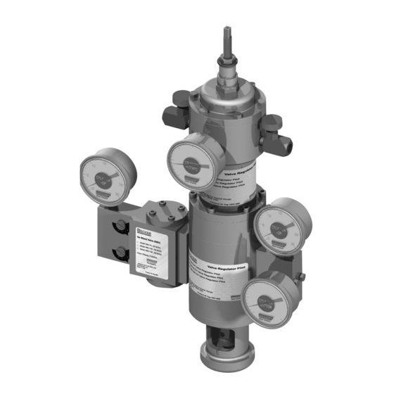
The GE’s Becker VRP-B-CH series balanced seat design, double- VRP-B-CH pilot may be used for pressure control applications with acting pilot represents a breakthrough in valve control technology setpoints ranging from 3 psig to 1500 psig. -
Page 5: Scope Of Manual
(when feature can be utilized) • Any large downstream systems (city gate stations, inter-system pressure limiting) • Suction control to reciprocating compressors © 2016 General Electric Company. All rights reserved. Becker VRP-B-CH Series Valve Regulator Pilot Instruction Manual | 2... -
Page 6: Technical Information
The letter after the seven-digit part number identify the pilot revision series. VRP-B-175-CH VRP-B-600-CH VRP-B-1000-CH VRP-B-1500-CH VRP-B-CH pilots – model numbers 3 | GE Oil & Gas © 2016 General Electric Company. All rights reserved. -
Page 7: Remote Setpoint Change Options
1903 kPa 6550 kPa 6550 kPa These models should only be used for applications that require high gain. Consult GE prior to selecting these models. Remote Setpoint Change Options • The SM-1000 series motors accept a 24 VDC or 120 VAC input. -
Page 8: Principles Of Operation
Principles of Operation GE’s Becker VRP-B-CH pilot and double-acting cylinder actuator can be used in conjunction with varying valve types to provide a complete package for stable, accurate pressure control over a wide range of applications. The energy for control valve operation comes from the pressure differential between the pilot supply and discharge pressures. -
Page 9: Adjustment Procedures
Table B – Exhaust Vented to Pressure System Cylinder Bore (In.) Supply Pressure (psig) Variable Orifice Number Up to 50 51-200 201-600 © 2016 General Electric Company. All rights reserved. Becker VRP-B-CH Series Valve Regulator Pilot Instruction Manual | 6... -
Page 10: Fine Tuning Procedures
VRP-B-CH is in service. Turn the sensitivity adjustment drum to the right (decreasing No other adjustments need to be made. GE recommends numbers) until the exhaust port just starts bleeding gas. noting the setpoint change per revolution of the control spring Check the total deadband again and repeat this process until installed in the pilot. -
Page 11: Inspection Procedure
8. Perform the internal friction test. the optimum setting, try several combinations of adjustable orifice settings. 9. Readjust the VRP-B-CH pilot if necessary. © 2016 General Electric Company. All rights reserved. Becker VRP-B-CH Series Valve Regulator Pilot Instruction Manual | 8... -
Page 12: Annual Maintenance Checklist
Balance Valve Assembly 35-1510 instruction. O-Ring -010 95-2609 Note: It is not necessary to replace any rubber goods in GE’s #10 Lockwasher 98-3178 Becker instrumentation or instrumentation accessories on Strainer for Balance Valve 35-1559 a regular basis. - Page 13 VRP-B-CH Pilot Blank Parts © 2016 General Electric Company. All rights reserved. Becker VRP-B-CH Series Valve Regulator Pilot Instruction Manual | 10...
- Page 14 1/4-20 x 2 in. SCHS (SS) for 600-CH Stainless steel versions available Item #10 is 98-2614 (8-32 x 1/2 inch SS) for VRP models 175/600-CH Spring Chamber 11 | GE Oil & Gas © 2016 General Electric Company. All rights reserved.
-
Page 15: Vrp-B-Ch Pilot Blank Without Bottom Cartridge Parts
(1) Stainless steel versions available (2) Item #10 is 98-2614 (8-32 x ½” SS) for VRP models (except 1500-CH) 1000/1500-CH Spring Chamber © 2016 General Electric Company. All rights reserved. Becker VRP-B-CH Series Valve Regulator Pilot Instruction Manual | 12... -
Page 16: Vrp-B-Ch Pilot Spring Chamber Parts
30-7011 Conv. Diaphragm w/Hole 95-2615 O-ring - 012 30-7058 Top Spacer 1000/1500-CH Sensing Chamber Stainless steel versions available Maximum allowable operating pressure (MAOP) = 1500 psig 13 | GE Oil & Gas © 2016 General Electric Company. All rights reserved. -
Page 17: Appendix
This is shown as t below: S x D = 0.148 x T + 460 © 2016 General Electric Company. All rights reserved. Becker VRP-B-CH Series Valve Regulator Pilot Instruction Manual | 14... -
Page 18: Accessories
NBV Series No Bleed Valve: Achieves non-bleeding conditions at both full open and full closed positions without any adjustment. Selection based upon power gas pressure and discharge gas pressure. 15 | GE Oil & Gas © 2016 General Electric Company. All rights reserved. -
Page 19: Assembly Procedures
2a. Turn valve adjusting screw (H) into the outside piston (I) until the screw head is flush with the piston recess. © 2016 General Electric Company. All rights reserved. Becker VRP-B-CH Series Valve Regulator Pilot Instruction Manual | 16... -
Page 20: Orifice Block Assembly
3a. Attach the orifice block (K) to the pilot body block (F) with two 1/4– 20 x 2-1/2-in stainless steel HHCS (J) by lining it up with roll pins (M) in pilot body block (F). 17 | GE Oil & Gas © 2016 General Electric Company. All rights reserved. - Page 21 4b. With the pressure source activated, soap test around the 4d. Remove all plugs from all blocks/manifolds (K and N). balanced valve assembly ( C) on both the bottom and the © 2016 General Electric Company. All rights reserved. Becker VRP-B-CH Series Valve Regulator Pilot Instruction Manual | 18...
- Page 22 6d. Assemble nut (Y) onto the outside piston (U) and torque it to 140-160 in. lbs. 6e. To assemble the inside piston, repeat Steps 6 to 6d. Convolute Convolute 19 | GE Oil & Gas © 2016 General Electric Company. All rights reserved.
- Page 23 Note: The cutout should face the orifice block’s supply port (K). single line. 8c. Rotating the diaphragm assembly clockwise until it stops (III). © 2016 General Electric Company. All rights reserved. Becker VRP-B-CH Series Valve Regulator Pilot Instruction Manual | 20...
- Page 24 (H). Attach the thread extension (E) to the inner tube (I) using 1/2-20 SS jam nut (J). Torque the jam nut (J) to 100-110 in.-lbs. 21 | GE Oil & Gas © 2016 General Electric Company. All rights reserved.
- Page 25 Jam Nut (J) in the cartridge assembly step. When Inner Tube (I) cannot be rotated any more do not force it, this assembly should only be hand-tight. © 2016 General Electric Company. All rights reserved. Becker VRP-B-CH Series Valve Regulator Pilot Instruction Manual | 22...
- Page 26 Fiberglass Washers (P) and six (6), 1/4-20 x 7/8” SHCS (Q). Bolt Bottom Flange (K) into Cartridge Spacer (G) using eight (8), 1/4-20 x 1 1/2” HHCS (R). 23 | GE Oil & Gas © 2016 General Electric Company. All rights reserved.
-
Page 27: 600-Ch Chamber Assemblies
Bolt the spring chamber (D) to the top body assembly (H) using six (6) fiberglass washers (J) and six (6) 1/4-20 x 2-inch SHCS (K). © 2016 General Electric Company. All rights reserved. Becker VRP-B-CH Series Valve Regulator Pilot Instruction Manual | 24... -
Page 28: 175-Ch Chamber Assemblies
(H). Attach the thread extension (E) to the inner tube (I) using 1/2-20 SS jam nut (J). Torque the jam nut (J) to 180-220 in.-lbs. 25 | GE Oil & Gas © 2016 General Electric Company. All rights reserved. -
Page 29: 175-Ch Chamber Assemblies (Cont.)
Thread 1/2-20 SS left-hand jam nut (F) onto the screw (E). The jam nut (F) and bearing nut (G) should be tightened against each other as shown in Figure 15. © 2016 General Electric Company. All rights reserved. Becker VRP-B-CH Series Valve Regulator Pilot Instruction Manual | 26... -
Page 30: Control Spring Assembly
If the spring (J) does touch any part of the screw (E), then replace the spring (J) and repeat the test. If the spring (J) is satisfactory then move to tube cap assembly. 27 | GE Oil & Gas © 2016 General Electric Company. All rights reserved. -
Page 31: 600-Ch Chamber Assemblies (Contd.)
(F) pressure ports. Bolt the cap (B) to the spring chamber (G) using six (6) 1/4-20 x 3/4-inch HHCS (H). © 2016 General Electric Company. All rights reserved. Becker VRP-B-CH Series Valve Regulator Pilot Instruction Manual | 28... -
Page 32: 1000/1500-Ch Chamber Assemblies (Contd.)
(F) pressure ports. Bolt the cap assembly (B) to the spring chamber (G) using twelve (12), 1/4-20 x 3/4-inch HHCS (H). 29 | GE Oil & Gas © 2016 General Electric Company. All rights reserved. -
Page 33: 1000/1500-Ch Chamber Assemblies (Contd.)
Parts Silhouettes © 2016 General Electric Company. All rights reserved. Becker VRP-B-CH Series Valve Regulator Pilot Instruction Manual | 30... - Page 34 Parts Silhouettes 31 | GE Oil & Gas © 2016 General Electric Company. All rights reserved.
- Page 35 Parts Silhouettes 30-7011 SMALL DIAPHRAGM FOR: 1000/1300-CH SENSING ASSEMBLY © 2016 General Electric Company. All rights reserved. Becker VRP-B-CH Series Valve Regulator Pilot Instruction Manual | 32...
- Page 36 DIRECT SALES OFFICE LOCATIONS AUSTRALIA ITALY SOUTH AFRICA Brisbane: Phone: +39-081-7892-111 Phone: +27-11-452-1550 Phone: +61-7-3001-4319 Fax: +39-081-7892-208 Fax: +27-11-452-6542 Fax: +61-7-3001-4399 JAPAN SOUTH AND CENTRAL Perth: Tokyo AMERICA AND THE CARIBBEAN Phone: +61-8-6595-7018 Phone: +81-03-6871-9008 Phone: +55-12-2134-1201 Fax: +61 8 6595-7299 Fax: +81-03-6890-4620 Fax:...
Need help?
Do you have a question about the Becker VRP-B-CH Series and is the answer not in the manual?
Questions and answers