Advertisement
Quick Links
Instruction Manual
1.
Safety Instructions
•
L frame (PML) and Open frame (PMB) options are to be manufactured by Delta and not to be
reconfigured by users from the standard enclosed configuration.
•
To ensure sufficient convection cooling, always maintain a safety distance of ≥ 20mm from all
ventilated surfaces while the device is in operation.
•
The device is not recommended to be placed on low thermal conductive surface like plastic.
•
Ensure the mounted device is kept at ≥ 4mm safety distance at all sides from other components
and equipments (Refer to Fig. 5).
•
Enclosure of the device can become very hot depending on the ambient temperature and load of
the power supply. Do not touch the device while it is in operation or immediately after power is
turned OFF. Risk of burning!
•
Do not touch the terminals while power is being supplied. Risk of electric shock.
•
Prevent any foreign metal, particles or conductors from entering the device during installation. It
may cause electric shock, safety hazard, fire or product failure.
•
The power supply must be mounted by metal screws onto a grounded metal surface. It is highly
recommended that the Earth terminal on the connector be connected to the grounded surface.
For Open Frame type of installation, ensure the power supply's Protective Earthing (Marked "PE"
in Fig. 5) point is connected to the system's Protective Earthing (PE). It is recommended that the
input FG (Fig. 1 location 1 ) be connected to the system's PE.
•
Warning (For Standard Terminal Block and Front Face Terminal Block products): When connecting
the device, secure Earth connection before connecting L and N. When disconnecting the device,
remove L and N connections before removing the Earth connection.
2.
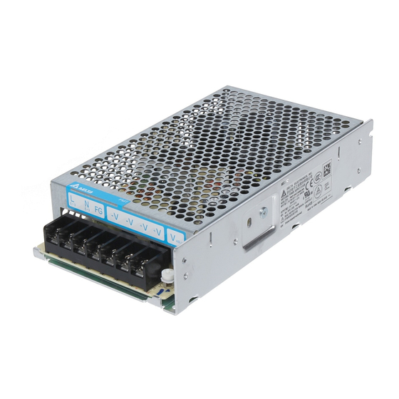
Device Descriptions
Refer to Fig. 1.:
1
Input & Output terminal block connector
2
DC voltage adjustment potentiometer
3
DC OK control LED (Green)
3.
Installation of the Device
Refer to Fig. 2.:
A
Mounting holes for the power supply (device). The device shall be mounted on minimum of 2
mounting holes using M3 screw of minimum 5mm length.
B
This surface belongs to customer's end system or panel where the device is mounted.
C
Connector
•
PM☐-☐V☐W1AA / PM☐-☐V☐W1AG: Use flexible cable (stranded or solid) of AWG No. 22-12.
User should calculate and select the suitable wire specification (type/quantity/diameter) according to
actual output current. The torque at the Connector shall not exceed 13Kgf.cm. The insulation
stripping length should not exceed 0.275" or 7mm (Refer to Fig. 3).
•
PM☐-☐V☐W1AH: Use flexible cable (stranded or solid) of AWG No. 28-18. Please refer to
Table 1 for the recommended Housing and Terminal.
Table 1:
Connector (Board Mounting)
Input (JST)
B3P5-VH(LF)(SN)
Output (JST)
B2P3-VH(LF)(SN)
4.
Installation of Mounting Accessories
•
For PMT and PML Series (Refer to Fig. 4): Only use M3 screw ≤ 3mm through the base mounting
holes. This is to keep a safe distance between the screw and internal components. Recommended
mounting tightening torque: 4~7Kgf.cm.
•
For PMB Series: (Refer to Fig. 5): The mounting holes on any mounting accessories for the device
should be kept at a diameter of < 6.5mm. This is to ensure sufficient safety distance between the
mounting screw and the components around the mounting holes on the PCBA. Therefore, the
diameter of the mounting screw should be kept at < 6.5mm.
REV.03
Housing
Terminal
VHR-5N
SVH-21T-P1.1
VHR-3N
PMT-☐V☐W1AA
2
3
Note:
and
are swapped for some models.
Fig. 1. Device Descriptions
Base Mounting (Vertical)
Side Mounting (Vertical)
Fig. 2. Mounting Orientation
(PM☐-☐V☐W1AA / PM☐-☐V☐W1AG)
Lug
Fig. 3. Wire Type
Fig. 4. Mounting Screw
PM☐-☐V☐W1A☐
PMT-☐V☐W1AG
• PMT-☐V☐W1AA:
Standard Terminal Block
• PMT-☐V☐W1AG:
Front Face Terminal Block
• PMT-☐V☐W1AH:
Harness Connector
• PML-☐V☐W1AA/AG/AH:
PMT-☐V☐W1AH
L Frame (without cover)
• PMB-☐V☐W1AA/AG/AH:
Open Frame (without cover
and chassis)
Side Mounting (Horizontal)
Open Frame Mounting
Stripped wire
D1 = 4.0 mm Min.
D2 = 6.0 mm Min. (For PMB Series)
Fig. 5. Assembly Reference
www.DeltaPSU.com
Advertisement

Related Manuals for Delta Electronics PMT V Series


Summary of Contents for Delta Electronics PMT V Series
- Page 1 Instruction Manual PM☐-☐V☐W1A☐ Safety Instructions PMT-☐V☐W1AA PMT-☐V☐W1AG • PMT-☐V☐W1AA: • L frame (PML) and Open frame (PMB) options are to be manufactured by Delta and not to be Standard Terminal Block reconfigured by users from the standard enclosed configuration. • To ensure sufficient convection cooling, always maintain a safety distance of ≥...
- Page 2 PM☐-☐V☐W1A☐ 使用说明书 安全规范 PMT-☐V☐W1AA PMT-☐V☐W1AG • PMT-☐V☐W1AA: • 不允许使用者将标准电源 (PMT) 自行拆解为无盖式 (PML) 或裸板式 (PMB) 后组装与使用。 标准连接端子 • 与通风表面保持至少 20mm 的安全距离,以确保对流冷却充分。 • • PMT-☐V☐W1AG: 本产品不适合摆放在低热导体,例如:塑胶。 • 本产品安装完成后,周围设备必须与本产品保持至少 4mm 的距离以满足安全规范 (请参考图五)。 朝前连接端子 • 受环境温度及产品负载的影响,本机外壳温度会很高,因此在上电时或切断电源后短时间内 • PMT-☐V☐W1AH: 不要触摸本机,以免烫伤。 线束连接端子 • 请勿在上电时触摸连接端子,以防电击危险。 PMT-☐V☐W1AH • PML-☐V☐W1AA/AG/AH: •...
Need help?
Do you have a question about the PMT V Series and is the answer not in the manual?
Questions and answers