Advertisement
Quick Links
Instruction Manual
1. Safety instructions
To ensure sufficient convection cooling, always maintain a safety
distance of >20mm from all ventilated surfaces while the device is in
operation.
The device is not recommended to be placed on low thermal
conductive surface, for example, plastics.
Note that the enclosure of the devi ce can become very hot
depending on the ambient temperature and load of the power supply.
Do not touch the device while it is in operation or immediately after
power is turned OFF. Risk of burning!
Do not touch the terminals while power is being supplied. Risk of
electric shock.
Prevent any foreign metal, particles or conductors to enter the device
t h r o u g h t h e o p e n i n g s d u r i n g i n s t a l l a t i o n . I t c a n c a u s e : -
- E l e c t r i c s h o c k ; S a f e t y H a z a r d ; F i r e ; P r o d u c t f a i l u r e
Warning: When connecting the device, secure Earth connection
before connecting L and N. When disconnecting the device, remove
L and N connections before removing the Earth connection.
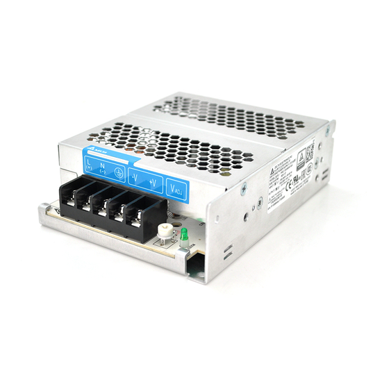
2. Device descriptions
Refer to Fig. 1.:
Input & Output terminal block connector
1
DC voltage adjustment potentiometer
2
3. Installation of the Device
Refer to Fig. 2.:
A
Mounting holes for power supply assembly onto the mounting surface.
Power supply shall be mounted on minimum 2 mounting holes using M3
screw minimum 5mm length.
This surface belongs to customer's end system or panel where the
B
power supply is mounted.
Connector
C
Use flexible cable (stranded or solid), AWG no. 14-22. The torque at the
Connector shall not exceed 7.1lbf.in The insulation stripping length
should not exceed 0.275" or 2mm Refer to Fig. 3.
4. Installation of Mounting Accessories
Only use M3 screw < 2mm through the base mounting holes. This is to
keep a safety distance between the screw and internal components.
Refer to Fig. 4.:
Recommended mounting tightening torque : 4~8Kgf.cm
REV.00
Fig. 1. Device Descriptions
Side Mounting (Vertical)
Base Mounting (Vertical)
Fig. 2. Mounting Orientation
Lug
Fig. 3. Wire Type
Fig. 4. Mounting Screw
EOE11010276
PMC-05V015W1AA
Side Mounting (Horizontal)
Stripped wire
P/N 5012279400
PAGE 3 OF 4
Advertisement

Subscribe to Our Youtube Channel
Related Manuals for Delta Electronics PMC Series


Summary of Contents for Delta Electronics PMC Series
- Page 1 EOE11010276 PMC-05V015W1AA Instruction Manual 1. Safety instructions To ensure sufficient convection cooling, always maintain a safety distance of >20mm from all ventilated surfaces while the device is in operation. The device is not recommended to be placed on low thermal conductive surface, for example, plastics.
- Page 2 EOE11010276 使用說明書 使用说明 PMC-05V015W1AA 1. 安全規範 1. 安全规范 與通風表面保持至少 20mm 的安全距離,以確保對流冷卻充分。 与通风表面保持至少 20mm 的安全距离,以确保对流冷却充分。 本產品不適合擺放在低熱導體,例如:塑膠。 本产品不适合摆放在低热导体,例如:塑胶。 受環境溫度及產品負載的影響,本機外殼溫度會很高,因 此在上電時或切 受环境温度及产品负载的影响,本机外壳温度会很高,因此在上电时或切 斷電源後短時間內不要觸摸本機,以免燙傷。 断电源后短时间内不要触摸本机,以免烫伤。 請勿在上電時觸摸連接端子,以防電擊危險。 请勿在上电时触摸连接端子,以防电击危险。 安裝過程中,應避免金屬元件或金屬導體通過空隙或通風孔進入到產品 安装过程中,应避免金属元件或金属导体通过空隙或通风孔进入到产品 內,否則會引起下列狀況。 内,否则会引起下列状况。 -電擊 ; 安全危害 ; 火災 ; 產品異常 -电击;安全危害;火灾;产品异常...
Need help?
Do you have a question about the PMC Series and is the answer not in the manual?
Questions and answers