Advertisement
Instruction Manual
1.
Safety Instructions
•
The device is not recommended to be placed on low thermal conductive surface. For
example, plastics.
•
For safety reasons, please ensure the mounted device is kept at ≥ 4mm safety distance at
all sides from other components and equipments. In addition, to ensure sufficient
convection cooling, always maintain a distance of ≥ 20mm from ventilated surfaces while
the device is in operation (Refer to Fig. 3).
•
Note that the enclosure of the device can become very hot depending on the ambient
temperature and load of the power supply. Do not touch the device while it is in operation
or immediately after power is turned OFF. Risk of burning!
•
Do not touch the terminals while power is being supplied. Risk of electric shock.
•
Prevent any foreign metal, particles or conductors from entering the device through the
openings during installation. It may cause: - Electric shock; Safety Hazard; Fire; Product
failure.
•
Warning: When connecting the device, secure Earth connection before connecting L and
N. When disconnecting the device, remove L and N connections before removing the
Earth connection. The power supply must be mounted by metal screws onto a grounded
metal surface. It is highly recommended that the Earth terminal on the connector be
connected to the grounded metal surface.
2.
Device Descriptions
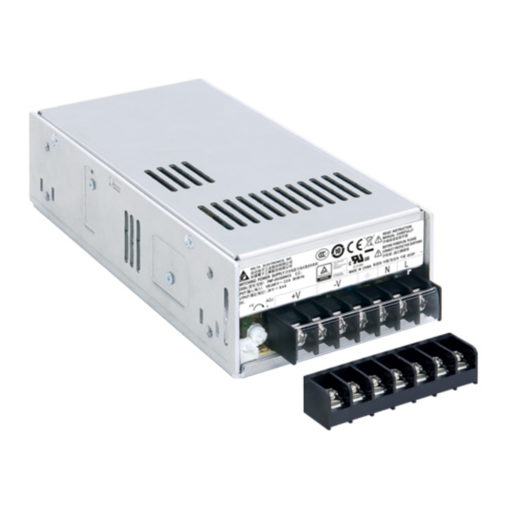
Refer to Fig. 1.:
1
Input & Output terminal block connector
2
DC voltage adjustment potentiometer
3
DC OK control LED (Green)
4
Remote ON/OFF function connector (Option)
3.
Installation of the Device
A
Side Mounting: Fig. 2 and Fig. 3 show the mounting hole locations for power supply
assembly onto a metal mounting surface. The power supply shall be mounted on
minimum of 4 mounting holes using M4 screw of maximum 4mm length (Refer to Fig.
5). This is to maintain a safety distance between the screw and internal components.
B
Base Mounting: Fig. 2 and Fig. 3 show the mounting hole locations for power supply
assembly onto a metal mounting surface. The power supply shall be mounted on
minimum of 4 mounting holes using M3 or 2 mounting holes using M4 screw of
maximum 4mm length (Refer to Fig. 5). This is to maintain a safety distance between
the screw and internal components.
C
Fig. 2: Connector
D
Fig. 2: This surface belongs to customer's end system or panel where the device is
mounted.
•
Use flexible cable (stranded or solid) of AWG No. 20-12. The input/output connectors'
allowable current is 23A max per pin. User should calculate and select the suitable wire
specification (type/quantity/diameter) according to actual output current. The torque at the
connector shall not exceed 13Kgf.cm. The insulation stripping length should not exceed
0.275" or 7mm (Refer to Fig. 4).
•
Recommended mounting torque of the product and its mounting accessories is 6~8Kgf.cm
(for M3 screw) or 9~12Kgf.cm (for M4 screw).
4.
Installation of Mounting Accessories
•
Please refer to the requirements in section 3 for the "Installation of the Device".
REV.00
PMF-24V200WCG☐, PMF-24V240WCG☐
(Front Face Terminal Block)
Fig. 1: Device Descriptions
Base Mounting (Horizontal)
Base Mounting (Vertical)
Fig. 2. Mounting Orientation
Fig. 3. Mounting Hole Locations and the Safety Distance
Lug
Stripped wire
Fig. 4. Wire Type
PMF-24V200WC☐☐ / PMF-24V240WC☐☐
PMF-24V200WCA☐, PMF-24V240WCA☐
(Standard Terminal Block)
Side Mounting (Horizontal)
Safety Distance
D1 = 4.0mm Min.
D2 = 20.0mm Min.
Fig. 5. Assembly Reference
www.DeltaPSU.com
Advertisement
Table of Contents

Related Manuals for Delta Electronics PMF Series


Summary of Contents for Delta Electronics PMF Series
- Page 1 Instruction Manual PMF-24V200WC☐☐ / PMF-24V240WC☐☐ Safety Instructions PMF-24V200WCG☐, PMF-24V240WCG☐ PMF-24V200WCA☐, PMF-24V240WCA☐ • The device is not recommended to be placed on low thermal conductive surface. For (Front Face Terminal Block) (Standard Terminal Block) example, plastics. • For safety reasons, please ensure the mounted device is kept at ≥ 4mm safety distance at all sides from other components and equipments.
- Page 2 PMF-24V200WC☐☐ / PMF-24V240WC☐☐ 使用說明書 使用说明书 安全規範 安全规范 • • 通電前需選擇正確電壓 (依據圖一)。 通电前需选择正确电压 (依据图一)。 • • 與通風表面保持至少 20mm 的距離,以確保對流冷卻充分。 与通风表面保持至少 20mm 的距离,以确保对流冷却充分。 • • 本產品不適合擺放在低熱導體,例如:塑膠。 本产品不适合摆放在低热导体,例如:塑胶。 • 本產品安裝完成後,周圍設備必須與本產品保持至少 4mm 的距離以滿足安全規範 • 本产品安装完成后,周围设备必须与本产品保持至少 4mm 的距离以满足安全规范 (依據圖三)。 (依据图三)。 • • 受環境溫度及產品負載的影響,本機外殼溫度會很高,因此在上電時或切斷電源後短 受环境温度及产品负载的影响,本机外壳温度会很高,因此在上电时或切断电源后短 時間內不要觸摸本機,以免燙傷。 时间内不要触摸本机,以免烫伤。...
Need help?
Do you have a question about the PMF Series and is the answer not in the manual?
Questions and answers