Chapters
Table of Contents

Related Manuals for OPTIKA MICROSCOPES B-290 Series


Summary of Contents for OPTIKA MICROSCOPES B-290 Series
- Page 1 B-290 Series INSTRUCTION MANUAL Model B-290 series (B-292 / B-292PLI / B-293 / B-293PLI) B-290LD series (B-292LD1.50 / B-292LD1 / B-293LD1.50 / B-293LD1) B-290TB series (B-290TB) Ver. 3.0 2019...
-
Page 2: Table Of Contents
Summary Warning Symbols and conventions Safety Information Intended use Overview B-292 / B-292PLI / B-293 / B-293PL B-292LD1.50 - B-292LD1 - B-293LD1.50 - B-293LD1 B-290TB Unpacking Assembling B-292 / B-292PLI / B-293 / B-293PLI B-292LD1 / B-292LD1.50 / B-293LD1 / B-293LD1.50 B-290TB Assembling the microscope 7.4.1 B-292 / B-292PLI / B-293 / B-293PLI... -
Page 3: Symbols And Conventions
Warning This microscope is a scientific precision instrument designed to last for many years with a minimum of maintenance. It is built to high optical and mechanical standards and to withstand daily use. We remind you that this manual contains important information on safety and maintenance, and that it must therefore be made accessible to the instrument users. -
Page 4: Overview
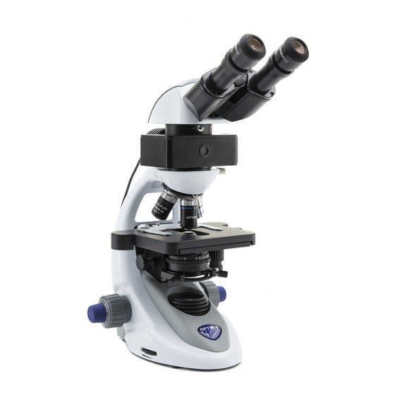
Overview B-292 / B-292PLI / B-293 / B-293PL PHOTO TUBE (ONLY FOR TRINOCULAR HEAD) EYEPIECES OBSERVATION HEAD -) BINOCULAR (B-292 / B-292PLI) -) TRINOCULAR (B-293 / B-293PLI) OBJECTIVES SLIDE HOLDER STAGE CONDENSER HEIGHT X/Y MOVEMENT ADJUSTMENT KNOBS KNOB CONDENSER CONDENSER CENTERING SCREWS FINE FOCUS KNOB COARSE FOCUS KNOB... -
Page 5: B-292Ld1.50 - B-292Ld1 - B-293Ld1.50 - B-293Ld1
B-292LD1.50 - B-292LD1 - B-293LD1.50 - B-293LD1 PHOTO TUBE (ONLY FOR TRINOCULAR HEAD) OBSERVATION HEAD EYEPIECES -) BINOCULAR (B-292LD1 / B-292LD1.50) -) TRINOCULAR (B-293LD1 / B-293LD1.50) FLUORESCENCE ATTACHMENT OBJECTIVES SLIDE HOLDER STAGE CONDENSER HEIGHT X/Y MOVEMENT ADJUSTMENT KNOBS KNOB CONDENSER CONDENSER CENTERING SCREWS FINE FOCUS KNOB... -
Page 6: B-290Tb
B-290TB TABLET DIGITAL HEAD EYEPIECES SLIDE HOLDER OBJECTIVES CONDENSER STAGE HEIGHT ADJUSTMENT KNOB X/Y MOVEMENT FINE FOCUS KNOB KNOBS COARSE FOCUS KNOB CONDENSER CENTERING SCREWS INTENSITY ADJUSTMENT DIAL Page 6... -
Page 7: Unpacking
Unpacking The microscope is housed in a moulded Styrofoam container. Remove the tape from the edge of the container and lift the top half of the container. Take some care to avoid that the optical items (objectives and eyepieces) fall out and get damaged. Using both hands (one around the arm and one around the base), lift the microscope from the container and put it on a stable desk. -
Page 8: B-292Ld1 / B-292Ld1.50 / B-293Ld1 / B-293Ld1.50
B-292LD1 / B-292LD1.50 / B-293LD1 / B-293LD1.50 ① ⑤ ③ ⑦ ② ⑧ ⑥ ④ ⑨ ① Frame ⑤ Objectives ② Observation head 10X/20X/40X/50X: B-292LD1.50 - B-293LD1.50 binocular (B-292LD1 / B-292LD1.50) 10X/20X/40X/100X(dry): B-292LD1 - B-293LD1 trinocular (B-293 / B-293PLI) ⑥ Dust cover ③... -
Page 9: B-290Tb
B-290TB ① ④ ③ ⑧ ⑦ ⑥ ⑤ ⑨ ② ⑭ ⑬ ⑩ ⑫ ⑪ ① Frame ⑧ Power supply ② Digital observation head ⑨ Tension adjustment tool ③ Eyepieces ⑩ Tablet power supply ④ Objectives (4X / 10X / 40X / 100X) ⑪... -
Page 10: Assembling The Microscope
Assembling the microscope 7.4.1 B-292 / B-292PLI / B-293 / B-293PLI 1. Remove the dust cap from the microscope frame and from the bottom of the observation head. 2. Insert the optical head above the stand and tighten the screw. (Fig. 1) • Hold the head with one hand during the lo- cking in order to avoid that the head falls. -
Page 11: B-292Ld1/B-292Ld1.50/B-293Ld1/B-2932Ld1.50
7.4.2 B-292LD1/B-292LD1.50/B-293LD1/B-2932LD1.50 1. Insert the fluorescence attachment above the frame and tighten the locking screw. (Fig. 5) Fig. 5 2. Insert the cable in the socket placed at the rear side of the microscope. (Fig. 6) Fig. 6 3. Insert the optical head above the stand and tighten the screw. -
Page 12: B-290Tb
5. Insert the power supply jack in the socket placed at the rear side of the microscope. (Fig. 3) Fig. 9 Only for trinocular head Unscrew the protection cap mounted on the photo port and screw the photo tube. (Fig. 4) Fig. - Page 13 4. Fix the rotating part of the junction using the black wing-nut ①. (Fig. 13) ① Fig. 13 5. Then hook the Tablet PC onto the 4 screws of the junction and pull toward down to firmly lock the Tablet PC in the holder.
-
Page 14: Polarizing Set (Optional)
Polarizing set (optional) 1. Place the polarizer on the light exit ① at the base of the microscope. (Fig. 16) ① Fig. 16 2. Loosen the head fixing knob ② and remove the head from the microscope frame. (Fig. 17) ②... -
Page 15: Use Of The Microscope
Use of the microscope ① Switching on the microscope Operate on the main switch ① placed in the rear side of the microscope, moving the selector on “I” (Fig. 19) Fig. 19 Light intensity adjustment Operate on the light intensity dial to increase or de- crease the illumination intensity. -
Page 16: Adjust The Interpupillary Distance
Adjust the interpupillary distance ① Hold the right and left parts of the observation head using both hands and adjust the interpupillary distan- ce by turning the two parts until one circle of light can be seen. (Fig. 23) • The graduation on the interpupillary distance in- dicator ①, pointed by the spot “.”... -
Page 17: Condenser Centering
Condenser centering The condenser is installed and pre-centered in the factory. ② To remove the condenser use an Allen wrench 1.5 mm and operate on the fixing knob placed on the right side of the condenser holder. Should a new centering is needed, operate in this ①... -
Page 18: Use Of Fluorescence
8.10 Use of fluorescence Operate on the main switch placed in the rear side of the microscope. Setting on “I” turns on transmitted light, setting on “II” turns on fluore- scence. Setting on “O” turns off the microscope. (Fig. Fig. 28 Move the filter selector in the “B” position (Fig. 29) to insert the fluorescence filter in the light path. -
Page 19: Microphotography
Microphotography Cameras with projection lens 1. Remove dust caps from camera and projection lens. 2. Screw the projection lens to camera thread. (Fig. Fig. 30 3. Insert the projection lens into the photo tube. (Fig. 31) Fig. 31 9.2 Reflex camera 1. -
Page 20: Troubleshooting
10. Troubleshooting Review the information in the table below to troubleshoot operating problems. PROBLEM CAUSE SOLUTION I. Optical Section: LED operates, but field of view re- Power supply is unplugged. Connect mains dark. Brightness is too low Set brightness to a proper level Fluorescence filter is not suitable Use a suitable filter for the specimen... - Page 21 IV. Observation tube Field of view of one eye does not Interpupillary distance is incorrect Adjust interpupillary distance match that of the other. Incorrect diopter adjustment Adjust diopter Your view is not accustomed to Quando guarda il campione non focalizzi microscope observation lo sguardo in un unico punto ma guardi l’intero campo visivo a disposizione.
-
Page 22: Maintenance
11. Maintenance To think about when and after using the microscope • The microscope should always be kept vertically when moving it and be careful so that no mo ving parts, such as the eyepieces, fall out. • Never mishandle or impose unnecessary force on the microscope. •... -
Page 23: Equipment Disposal
Equipment disposal Art.13 Dlsg 25 July 2005 N°151. “According to directives 2002/95/EC, 2002/96/EC and 2003/108/EC relating to the reduction in the use of hazardous substances in electrical and electronic equipment and waste dispo- sal.” The basket symbol on equipment or on its box indicates that the product at the end of its useful life should be collected separately from other waste. - Page 24 OPTIKA S.r.l. ® Via Rigla, 30 - 24010 Ponteranica (BG) - ITALY Tel.: +39 035.571.392 info@optikamicroscopes.com - www.optikamicroscopes.com OPTIKA Spain spain@optikamicroscopes.com OPTIKA USA usa@optikamicroscopes.com OPTIKA China china@optikamicroscopes.com OPTIKA India india@optikamicroscopes.com OPTIKA Central America camerica@optikamicroscopes.com...
- Page 25 Serie B-290 MANUALE DI ISTRUZIONI Modelli Serie B-290 (B-292 / B-292PLI / B-293 / B-293PLI) Serie B-290LD (B-292LD1.50 / B-292LD1 / B-293LD1.50 / B-293LD1) Serie B-290TB Ver. 3.0 2019...
- Page 26 Sommario Avvertenza Simboli Informazioni sulla sicurezza Utilizzo previsto Descrizione dello strumento B-292 / B-292PLI / B-293 / B-293PLI B-292LD1.50 - B-292LD1 - B-293LD1.50 - B-293LD1 B-290TB Disimballaggio Assemblaggio B-292 / B-292PLI / B-293 / B-293PLI B-292LD1 / B-292LD1.50 / B-293LD1 / B-293LD1.50 B-290TB Procedura di assemblaggio 7.4.1 B-292 / B-292PLI / B-293 / B-293PLI...
-
Page 27: Simboli
Avvertenza Questo microscopio è uno strumento scientifico di alta precisione, progettato per durare a lungo con una minima manutenzione; la realizzazione è secondo i migliori standard ottici e meccanici, per poter essere utilizzato quotidianamente. Vi ricordiamo che questo manuale contiene informazioni importanti per la sicurezza e per la manutenzione dello strumento, e deve quindi essere messo a disposizione di coloro che lo utilizzeranno. -
Page 28: Descrizione Dello Strumento
Descrizione dello strumento B-292 / B-292PLI / B-293 / B-293PLI TUBO FOTOGRAFICO (SOLO PER TESTE TRINOCULARI) OCULARI TESTA DI OSSERVAZIONE -) BINOCULARE (B-292 / B-292PLI) -) TRINOCULARE (B-293 / B-293PLI) OBIETTIVI FERMAVETRINO TAVOLINO MANOPOLA REGOLAZIONE MANOPOLE ALTEZZA TRASLAZIONE X/Y CONDENSATORE CONDENSATORE VITI DI CENTRAGGIO CONDENSATORE... -
Page 29: B-292Ld1.50 - B-292Ld1 - B-293Ld1.50 - B-293Ld1
B-292LD1.50 - B-292LD1 - B-293LD1.50 - B-293LD1 TUBO FOTOGRAFICO (SOLO PER TESTE TRINOCULARI) TESTA DI OSSERVAZIONE OCULARI -) BINOCULARE (B-292LD1 / B-292LD1.50) -) TRINOCULARE (B-293LD1 / B-293LD1.50) ILLUMINATORE PER FLUORESCENZA OBIETTIVI FERMAVETRINO TAVOLINO MANOPOLA REGOLAZIONE MANOPOLE ALTEZZA TRASLAZIONE X/Y CONDENSATORE CONDENSATORE VITI DI CENTRAGGIO CONDENSATORE... -
Page 30: B-290Tb 30
B-290TB TABLET TESTA DIGITALE OCULARI FERMAVETRINO OBIETTIVI MANOPOLA REGOLAZIONE TAVOLINO ALTEZZA CONDENSATORE MANOPOLE MANOPOLA TRASLAZIONE X/Y MACROMETRICA DI MESSA A FUOCO MANOPOLA MICROMETRICA DI MESSA A FUOCO VITI DI CENTRAGGIO CONDENSATORE MANOPOLA REGOLAZIONE INTENSITÀ Pagina 30... -
Page 31: Disimballaggio
Disimballaggio Il microscopio si trova in un imballaggio di polistirolo espanso stampato. Dopo aver tolto il nastro ade- sivo da tutti gli imballi, sollevare la metà superiore dell’imballaggio. Fare attenzione a non far cade- re o danneggiare i componenti ottici (obiettivi e oculari). Estrarre il microscopio dal suo imballaggio con entrambe le mani (una intorno al braccio e una intorno alla base) e appoggiarlo su un piano stabile. -
Page 32: B-292Ld1 / B-292Ld1.50 / B-293Ld1 / B-293Ld1.50
B-292LD1 / B-292LD1.50 / B-293LD1 / B-293LD1.50 ① ⑤ ③ ⑦ ② ⑧ ⑥ ④ ⑨ ① Stativo ⑤ Obiettivi ② Testa di osservazione 10X / 20X / 40X / 50X: B-292LD1.50 - B-293LD1.50 binoculare (B-292LD1 / B-292LD1.50) 10X / 20X / 40X / 100X(dry): B-292LD1 - B-293LD1 trinoculare (B-293 / B-293PLI) ⑥... -
Page 33: B-290Tb
B-290TB ① ④ ③ ⑧ ⑦ ⑥ ⑤ ⑨ ② ⑭ ⑬ ⑩ ⑫ ⑪ ① Stativo ⑧ Alimentatore ② Testa di osservazione digitale ⑨ Chiave regolazione tensione ③ Oculari ⑩ Alimentatore tablet ④ Obiettivi (4X / 10X / 40X / 100X) ⑪... -
Page 34: Procedura Di Assemblaggio
Procedura di assemblaggio 7.4.1 B-292 / B-292PLI / B-293 / B-293PLI 1. Rimuovere il tappo di protezione dallo stativo e dalla parte sottostante della testa di osservazio- 2. Inserire la testa sullo stativo e serrare la vite di fissaggio. (Fig. 1) • Tenere sempre la testata con una mano du- rante il serraggio della vite per evitare che la stessa cada. -
Page 35: B-292Ld1/B-292Ld1.50/B-293Ld1/B-2932Ld1.50
7.4.2 B-292LD1/B-292LD1.50/B-293LD1/B-2932LD1.50 1. Inserire l’illuminatore per fluorescenza sopra lo stativo e serrare la vite. (Fig. 5) Fig. 5 2. Collegare il cavo al connettore posto nella parte posteriore dello stativo. (Fig. 6) Fig. 6 3. Inserire la testa sullo stativo e serrare la vite di fissaggio. -
Page 36: B-290Tb
5. Inserire lo spinotto dell’alimentatore nel connet- tore posto sul retro del microscopio. (Fig. 9) Fig. 9 Solo per teste trinoculari Svitare il tappo di protezione montato sulla terza uscita ed avvitare il tubo fotografico. (Fig. 10) Fig. 10 7.4.3 B-290TB 1. - Page 37 4. Fissare la parte ruotabile del supporto stringen- do la manopola nera ① a lato. (Fig. 13) ① Fig. 13 5. Successivamente agganciare il Tablet PC alle 4 viti del supporto e tirare verso il basso per bloc- care in modo sicuro il tablet sulla staffa. (Fig. 14) •...
-
Page 38: Set Di Polarizzazione (Opzionale)
Set di polarizzazione (opzionale) 1. Posizionare il polarizzatore ① sulla lente di cam- po del microscopio. (Fig. 16) ① Fig. 16 2. Allentare la manopola di fissaggio della testa ② e rimuovere la testa di osservazione dallo stativo. (Fig. 17) ②... -
Page 39: Uso Del Microscopio
Uso del microscopio ① Accensione del microscopio Agire sull’interruttore principale ① posto nella parte posteriore dello strumento portando il selettore su “I”. (Fig. 19) Fig. 19 Regolazione intensità luminosa Agire sulla rotellina di regolazione dell’intensità lumi- nosa per aumentare o diminuire il voltaggio dell’illu- minazione. -
Page 40: Regolazione Della Distanza Interpupillare
① Regolazione della distanza interpupillare Osservando con entrambi gli occhi, sostenere il gruppo di oculari. Ruotare questi lungo l’asse comu- ne fino ad ottenere un unico campo visivo. (Fig. 23) • La scala graduata sull’indicatore della distanza interpupillare ①, indicata dal puntino “.” sul por- taoculare, mostra la distanza interpupillare dell’o- peratore. -
Page 41: Centraggio Del Condensatore
Centraggio del condensatore Il condensatore viene montato e pre-centrato prima della spedizione dalla fabbrica. Per rimuovere il condensatore usare una chiave a ② brugola da 1.5 mm ed agire sulla vite di fissaggio posta sulla parte destra del portacondensatore. Qualora si rendesse necessario effettuare un nuovo ①... -
Page 42: Uso Della Fluorescenza
8.10 Uso della fluorescenza Agire sull’interruttore principale per accendere/ spegnere lo strumento. Il posizionamento su “I” accende la luce trasmessa, mentre il posizio- namento su “II” accende la fluorescenza. Il posizionamento su “O” spegne lo strumento. (Fig. 28) Fig. 28 Spostare il selettore portafiltri nella posizione “B”... -
Page 43: Microfotografia
9. Microfotografia Telecamere con lente di proiezione 1. Rimuovere i tappi antipolvere dalla telecamera e dalla lente di proiezione. 2. Avvitare la lente di proiezione al filetto della tele- camera. (Fig. 30) Fig. 30 3. Inserire la parte terminale della lente di proiezio- ne nel tubo vuoto della terza uscita. -
Page 44: Risoluzione Dei Problemi
10. Risoluzione dei problemi Consultare le informazioni riportate nella tabella seguente per risolvere eventuali problemi operativi. PROBLEMA CAUSA SOLUZIONE I. Sezione Ottica: Il microscopio è acceso, ma il campo L’alimentatore è scollegato. Collegarlo visivo è scuro. La luminosità è troppo bassa Regolarla ad un livello adeguato Il cubo per fluorescenza non è... - Page 45 IV. Tubo di Osservazione Il campo visivo è diverso per ciascun La distanza interpupillare non è Regolare la distanza interpupillare occhio. corretta La correzione diottrica non è Regolare la correzione diottrica giusta La tecnica di visione non è cor- Quando guarda il campione non focalizzi retta, e l’operatore sforza la vista lo sguardo in un unico punto ma guardi l’intero campo visivo a disposizione.
-
Page 46: Manutenzione
11. Manutenzione Prima e dopo l’utilizzo del microscopio • Tenere il microscopio sempre in posizione verticale quando lo si sposta. • Assicurarsi inoltre che le parti mobili, ad esempio gli oculari, non cadano. • Non maneggiare senza precauzioni e non adoperare inutile forza sul microscopio. •... -
Page 47: Smaltimento
Smaltimento Ai sensi dell’articolo 13 del decreto legislativo 25 luglio 2005 n°151. “Attuazione delle direttive 2002/95/CE, 2002/96/ CE e 2003/108/CE, relative alla riduzione dell’uso di sostanze pericolose nelle apparecchiature elettriche ed elet- troniche, nonché allo smaltimento dei rifiuti”. Il simbolo del cassonetto riportato sulla apparecchiatura o sulla sua confezione indica che il prodotto alla fine del- la propria vita utile deve essere raccolto separatamente degli altri rifiuti. - Page 48 OPTIKA S.r.l. ® Via Rigla, 30 - 24010 Ponteranica (BG) - ITALY Tel.: +39 035.571.392 info@optikamicroscopes.com - www.optikamicroscopes.com OPTIKA Spain spain@optikamicroscopes.com OPTIKA USA usa@optikamicroscopes.com OPTIKA China 100 Lauman Lane, Suite A, Hicksville, NY 11801 Tel: (877) 877-7274 | Fax: (516) 801-2046 china@optikamicroscopes.com Email: Info@nyscopes.com www.microscopeinternational.com...
Need help?
Do you have a question about the B-290 Series and is the answer not in the manual?
Questions and answers