
Subscribe to Our Youtube Channel
Related Manuals for Humminbird PiranhaMAX 165


Summary of Contents for Humminbird PiranhaMAX 165
- Page 1 PiranhaMAX 165, 175, 176i, 195c, & 196ci PiranhaMAX 165, 175, 176i, 195c, & 196ci Installation and Operations Manual Installation and Operations Manual 532030-1_A...
- Page 2 Web site at humminbird.com. The following models are covered in this manual: • PiranhaMAX 165 - Single Beam, 240 V x 160 H Monochrome Display • PiranhaMAX 175 - Dual Beam, 240 V x 160 H Monochrome Display • PiranhaMAX 176i - Dual Beam, 240 V x 160 H Monochrome Display •...
- Page 3 To obtain a list of authorized international distributors, please visit our Web site at humminbird.com or contact our Customer Resource Center at (334) 687-6613. Humminbird®, Fish ID+™, Structure ID®, and WhiteLine™ are trademarked by or registered trademarks of Johnson Outdoors Marine Electronics, Inc.
-
Page 4: Table Of Contents
Table of Contents Installation Overview Fixed Control Head Installation Determine Where to Mount ......... 2 Connect the Power Cable to the Boat . - Page 5 Set Up the Control Head Contrast (PiranhaMAX 165, 175, and 176i models only) ......Fish ID+™...
- Page 6 U.S. are not intended for resale in the international market. To obtain a list of authorized International Distributors, please visit our Web site at humminbird.com or contact our Customer Resource Center at 1-800-633-1468 to locate the distributor nearest you.
-
Page 7: Installation Overview
Installation Overview Before you start installation, we encourage you to read these instructions carefully in order to get the full benefit from your PiranhaMAX. There are three basic installation tasks that you must perform for the PiranhaMAX: • Installing the Control Head •... -
Page 8: Fixed Control Head Installation
Fixed Control Head Installation 1. Determine Where to Mount Begin the installation by determining where to mount the control head. Consider the following to determine the best location: • To check the location planned for the control head, test run the cables for the power and transducer. - Page 9 NOTE: Humminbird® is not responsible for over-voltage or over-current failures. The control head must have adequate protection through the proper selection and installation of a 1 amp fuse. 1a. If a fuse terminal is available, use crimp-on type electrical connectors (not included) that match the terminal on the fuse panel.
-
Page 10: Assemble The Control Head Base
3. Assemble the Control Head Base Your control head base will have a tilt and swivel mount. See the instructions below to assemble and mount the control head base. Tilt and Swivel Mount To assemble a tilt and swivel mount: Control Head Base Assembly 1. -
Page 11: Route The Control Head Cables Under The Deck
4. Route the Control Head Cables Under the Deck Use the following steps to route the control head cables under the deck. NOTE: Under the deck cable routing is not always possible. If this is not an option, the cables should be routed and secured above deck. NOTE: See Transom Transducer Installation in order to plan the location of the transducer and cable route. -
Page 12: Attach The Control Head To The Base
5. Attach the Control Head to the Base Follow these steps to attach the control head to the already-assembled base: NOTE: The transducer cable and power cable should be routed prior to securing the mounting bracket to the deck. 1. Apply marine-grade silicone sealant to the drilled holes for the mounting bracket. -
Page 13: Attach The Cables To The Control Head
5. Align the pivot knuckle with the mount base arms and slide into place, twisting slightly if necessary, until the unit is firmly seated. 6. Rotate the control head to the desired angle and hand tighten the thumbknob bolt. 7. Thread the gimbal knob onto the pivot bolt and tighten. 6. -
Page 14: Transom Transducer Installation Overview
NOTE: If you cannot find a transom mount location that will work for your boat hull, a different mounting technique or transducer type should be considered. See the FAQ (Frequently Asked Questions) section of our Web site at humminbird.com or call our Customer Resource Center at 1-800-633-1468 . -
Page 15: Transom Transducer Installation
Transom Transducer Installation 1. Locate the Transducer Mounting Position Turbulence: You must first determine the best location on the transom to install the transducer. It is very important to locate the transducer in an area that is relatively free of turbulent water. Consider the following to find the best location with the least amount of turbulence: •... -
Page 16: Prepare The Mounting Location
NOTE: If you cannot find a transom mount location that will work for your high-speed application, please visit the FAQ (Frequently Asked Questions) section of our Web site at humminbird.com or call our Customer Resource Center at 1-800-633-1468. 2. Prepare the Mounting Location After determining the mounting location for the transducer, follow the steps below to position and mount the transducer bracket. - Page 17 1. Make sure that the boat is level on the trailer, both Positioning the Mounting Bracket from port to starboard and from bow to stern, by Level placing your level on the deck of the boat, first in one direction, then in the other. 2.
-
Page 18: Assemble And Mount The Transducer
4. Make sure that the drill bit is perpendicular to the actual surface of the transom, NOT parallel to the ground, before you drill. Using a 5/32” bit, drill the two holes only to a depth of approximately 1”. NOTE: On fiberglass hulls, it is best to use progressively larger drill bits to reduce the chance of chipping or flaking the outer coating. - Page 19 2. Place the two ratchets, one on either side of Measuring the Transom Angle the transducer knuckle, so that the beads on each ratchet line up with the desired position number on the knuckle (Figure 18a). If you are setting the ratchets at position 1, the beads Plumb Line on each ratchet will line up with the rib on the...
- Page 20 3. Put the pivot bolt through the assembly to Inserting the Pivot Bolt hold it in position and loosely install the nut, but do NOT tighten the nut at this time (Figure 19). CAUTION! Do not use a high speed driver on this combination of fasteners.
- Page 21 6. Adjust the transducer assembly vertically, Adjusting the Transducer Mounting Position until the seam on the leading edge of the transducer (the edge closest to the transom of the boat) is level and just slightly below the hull (Figure 23). NOTE: The transducer has a natural downward slant of 4-5 degrees from leading edge (closest to the boat transom) to trailing edge (farthest away from the boat).
-
Page 22: Route The Cable
If the cable is too short, extension cables are available to extend the transducer cable up to a total of 50'. For assistance, contact the Customer Resource Center at humminbird.com or call 1-800-633-1468 for more information. - Page 23 3. Place the escutcheon plate over the cable Routing the Cable hole and use it as a guide to mark the two escutcheon plate mounting holes. Remove the plate, drill two 9/64" diameter x 5/8" deep holes, and then fill both holes with marine- grade silicone sealant.
-
Page 24: Test And Finish The Installation
2. If all connections are correct and power is available, the Humminbird® control head will enter Normal operation. 3. If the bottom is visible on-screen with a digital depth readout, the unit is working properly. - Page 25 NOTE: It is often necessary to make several incremental transducer adjustments before optimum high speed performance is achieved. Due to the wide variety of boat hulls, however, it is not always possible to obtain high speed depth readings. 6. Once you have reached a consistently good sonar signal at the desired speeds, you are ready to lock down the transducer settings.
-
Page 26: Piranhamax Portable Case Assembly
PiranhaMAX Portable Case Assembly It is important to perform the PiranhaMAX portable case assembly tasks in order, referring to the step-by-step procedures that represent the following main assembly tasks: • Assembling the PiranhaMAX mount • Assembling the base and handle •... -
Page 27: Assemble The Control Head Base
1. Assemble the Control Head Base Your control head base will have a tilt and swivel mount. See the instructions below to assemble and mount the control head base. Tilt and Swivel Mount To assemble a tilt and swivel mount: Control Head Base Assembly 1. -
Page 28: Assemble The Base And Handle
2. Assemble the Base and Handle In this procedure, you will install the PiranhaMAX mount and handle to the base of the portable case. 1. Turn the base upside down. Punch Punching Holes out the mounting holes labeled “C” with a hammer and a screwdriver (or an awl) as shown in the illustration Punching Holes. -
Page 29: Attach The Control Head To The Base And Handle
4. Install the handle onto the base, so that the curved part of the handle faces towards the back of the base, towards the battery well. Use the four included #8-32 x 7/16" screws, two on each side, to attach the handle to the base (see the illustrations Installing the Handle Onto the Base and Sliding in the Handle). -
Page 30: Route The Cables
Attaching the Control Head to the Base and Handle Pivot Knuckle Thumbknob Gimbal Knob Bolt Gimbal Knob Rear View Front View Figure 32 4. Route the Cables In this procedure, you will route the power Attaching the Battery Tie-Down Straps and transducer jumper cables on the underside of the base, and attach the tie- down straps that will be used to secure... - Page 31 2. Route the power cable from the mount Pulling the Cables Through the Base DOWN through the center hole of the base. Route the transducer jump cable UP through the base and mount. (Figure 34) 3. Connect the cables to the control head. The slots for the plugs are keyed to prevent reverse installation, and insertion should be easy.
- Page 32 6. Fit the transducer jumper cable connector down into the jumper cable well and snap it into place. Insert the two #6-32 x 1/4" screws included to secure the transducer jumper connector and tighten using a Phillips screwdriver. Hand tighten only! 7.
-
Page 33: Assemble The Portable Case
5. Assemble the Portable Case In this procedure, you will install the base assembly into the portable case. 1. Unzip the largest opening on the front of the portable case. 2. Insert the base assembly into the portable case, so that the PiranhaMAX control head is facing out of the case. -
Page 34: Assemble The Transducer Mounting Bracket
Installing the Battery Tying Down the Battery Figure 39 3. Pull the two battery tie-down straps over the top of the battery and connect both ends of each strap over the top, making sure that the straps are pulled tight around the battery and that the battery is seated securely in the battery well. -
Page 35: Stow The Portable Transducer And Battery Charger Into The Portable Case
2. Assemble the other transducer parts as shown (see the illustration Assembling the Portable Bracket below). Hand tighten only! Assembling the Portable Bracket Suction Cup Portable Transducer Assembly Phillips Head Screw Washer Bolt Wing Nut Ratchet Figure 41 NOTE: If you are unable to ratchet the transducer so Ratchets Placed in Position 2 that it rests below the water and points straight Bead... -
Page 36: Installing The Portable Case On The Boat
Installing the Portable Case on the Boat Since the portable case has a large non-skid mounting surface, it may be attached to almost any surface. In this section, you will route the cables on the boat, connect the transducer and power cables to the portable case, and attach the portable case to a dry and convenient location on your boat. -
Page 37: Attach The Portable Case To The Boat
(not provided) through the D-rings on either side of the portable case. NOTE: Humminbird® recommends that you do NOT position the portable case on the bottom of the boat, or in a location where it can be splashed by or immersed in water, as the portable case is water resistant, but not waterproof. -
Page 38: Mounting The Portable Transducer
Mounting the transducer to the boat is a simple yet important operation. A poor mounting location will affect the overall performance of the Humminbird® unit, so follow the mounting instructions carefully. It is important that the mounting position allows the transducer to rest beneath the surface of the water, pointing straight down. - Page 39 NOTE: If you are trolling, it is best to mount the transducer on the transom of the boat. 1. Mount the transducer so that it points straight down and so that the transducer itself is submerged in the water (see the illustration Portable Transducer Mount).
-
Page 40: Moving The Portable Fishfinder
Moving the Portable Fishfinder You should take the portable case with you when you leave the boat and will not be using it. Perform the following steps to make your unit mobile: 1. With the boat engine off, loosen all cable retainers/clips holding the transducer. -
Page 41: Power On And Off
Power ON and OFF Use the following instructions to power on your PiranhaMAX unit: • Power On: Press the POWER/MENU key until the PiranhaMAX powers on, then release the key. • Start-Up Menu: When the PiranhaMAX powers on, the Start-Up menu temporarily appears. From this menu, select either Normal or Simulator. -
Page 42: Piranhamax Sonar Technology
PiranhaMAX Sonar Technology The PiranhaMAX is the easiest to use fishfinder ever. For most anglers, all you’ll ever need to do is power on and fish! The PiranhaMAX automatically determines depth and makes adjustments to keep the bottom and fish visible on the display. -
Page 43: Single Beam Sonar
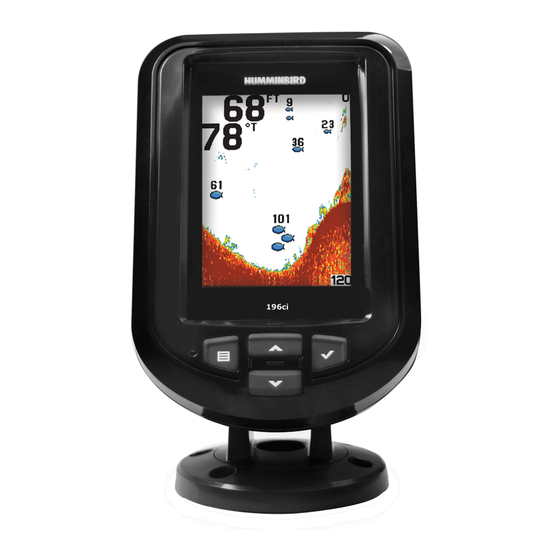
Single Beam Sonar The PiranhaMAX 165 uses a 200 kHz single beam sonar system with a 28° area of coverage. Boat speed, wave action, bottom hardness, water conditions and transducer installation can all affect depth capability. Dual Beam Sonar The PiranhaMAX 175, 176i, 195c, and 196ci use a 200/455 kHz dual beam sonar system with a 28°... -
Page 44: What You See On The Display
What You See on the Display The PiranhaMAX displays underwater information in an easy-to-understand format. The top of the display corresponds to the water surface at the transducer, and the bottom of the display corresponds to the Depth Range automatically selected for the current water depth. The Bottom Contour varies as the depth under the boat changes. -
Page 45: How Gps Works
How GPS Works If your PiranhaMAX model includes GPS (Global Positioning System), it will use GPS and sonar to determine your current track, display it on a grid, and provide detailed underwater information. GPS uses a constellation of satellites that continually send radio signals to the earth. -
Page 46: The Piranhamax Control Head
The PiranhaMAX Control Head Your PiranhaMAX unit interface is easy to use. A combination of keys and special features allows you to control what you see on the display. Refer to the following illustration, and see Key Functions for more information. Display POWER/MENU CHECK/ENTER... -
Page 47: Key Functions
Key Functions Your Fishfinder has a set of easy to use keys that give you flexibility and control over your fishing experience. POWER/MENU Key The POWER/MENU key is used to power the PiranhaMAX on and off. It is also used to open and close the menu system. •... -
Page 48: Check/Enter Key
CHECK/ENTER Key The CHECK/ENTER Key has multiple functions, which depend on the view, menu, or situation. • Menu Activation: Press the CHECK/ENTER key after selecting a menu option to activate the menu or open a submenu. NOTE: See How to Use the Menu System for more information. •... -
Page 49: How To Use The Menu System
How to Use the Menu System Review the instructions below to understand how to use the menu system. 1. Open the Menu System Press the POWER/MENU key. 2. Select a Menu Option Press the UP or DOWN Arrow key to select a menu option. NOTE: Available menu options will be determined by the view currently displayed on-screen. - Page 50 Adjust a Menu Setting: After a menu is selected, press the UP or DOWN Arrow keys to adjust the menu setting. Press the CHECK/ENTER key or the POWER/MENU key to confirm the selection. Menu settings are saved and removed from the screen automatically after several seconds. NOTE: In Normal operating mode, most menu settings saved to memory will not return to their default values when the unit is turned off.
-
Page 51: Set Up The Control Head
• International Units will have menu options such as Language and Units of Measurement for depth, speed, distance, and temperature. NOTE: Menu options are determined by your Humminbird® model. See the following pages for full menu descriptions. NOTE: If Simulator Mode is selected from the Start-Up Menu and a transducer is plugged in, some menu setting changes will be saved in memory even after the unit is powered down. -
Page 52: Contrast (Piranhamax 165, 175, And 176I Models Only)
Bottom View (Sonar View only) Settings: PiranhaMAX 165, 175, and 176i: Structure ID, Black, WhiteLine, Inverse; PiranhaMAX 195c and 196ci: Structure ID, WhiteLine; Default = Structure ID, Setting Saved in Memory Bottom View selects the method used to represent the bottom and structure on the display. - Page 53 Structure ID® represents weak returns as light pixels and strong returns as dark pixels. This has the benefit of ensuring that strong returns will be clearly visible on the display. Black (Bottom Black [monochrome models only]) displays all pixels below the bottom contour as black, regardless of signal strength.
-
Page 54: Reset
Reset Settings: Select CONFIRM and press the CHECK/ENTER key to activate. Use this menu choice with caution! Reset restores ALL menu settings to their factory defaults. Language (International Models only) Settings Vary; Default = English, Setting Saved in Memory Language selects the display language for menus. Units - Distance (Units submenu) Settings: Domestic Models: Miles (MI), Nautical Miles;... -
Page 55: Views
Views The sonar and navigation information from your Fishfinder are displayed on the screen in a variety of easy-to-read views. • Default View: When you first power up the control head, Sonar View will be the default view. • Available Views: The available views on your PiranhaMAX unit will vary with the model. -
Page 56: Status View
Status View Status View displays current data, including the unit model number, serial number, and battery status. • PiranhaMAX models that include GPS will also display GPS data, such as GPS Fix, latitude and longitude, average satellite strength (CNO Avg.), and HDOP (the Horizontal Dilution of Precision). HDOP is a GPS system parameter which depends on the current satellite configuration. -
Page 57: Sonar View
CHECK/ENTER key to mark the current position of the boat as a waypoint. Waypoints are saved in numerical order. NOTE: Waypoints are saved to the unit even after it is powered off. Tracks are not saved after the unit is powered off. Sonar View (PiranhaMAX 165) Upper Range Depth Surface Clutter... -
Page 58: Sonar Menu
• Customize the Sonar View Display: Set the Depth Range, Chart Speed, Zoom level, etc. NOTE: Menu options are determined by your Humminbird® model. See the following pages for full menu descriptions. • Access Sonar Setup Menu Options: Open the Setup submenu to set the Contrast, Bottom View, and Fish ID+™... -
Page 59: View
View Settings: Sonar, Track (PiranhaMAX 176i and 196ci only), Status; Default = Sonar View selects a view to be displayed on the screen. Depth Range Settings: Auto, 15 ft - 600 ft, 5 m - 184 m (International Models only); Default = Auto Depth Range sets the deepest depth range that will be displayed by the unit. -
Page 60: Zoom
Zoom Settings: Off, Auto, Manual Ranges; Default = Off Zoom provides a magnified view of the bottom and structure. Auto: Select Auto to magnify the area around the bottom in order to reveal fish and structure close to the bottom that may not be visible during normal operation. -
Page 61: Filter
NOTE: Continuous backlight operation will significantly decrease the battery life for PiranhaMAX Portables. Beam Select Settings: PiranhaMAX 165: 200 kHz; PiranhaMAX 175, 176i, 195c, and 196ci: 200 kHz, 455 kHz; Default = 200 kHz Beam Select sets which sonar returns from the transducer will be displayed on the screen. -
Page 62: Track View (Piranhamax 176I And 196Ci Only)
Track View (PiranhaMAX 176i and 196ci only) Track View displays the current track (also known as the position history or breadcrumb trail) showing where the boat has been, along with saved waypoints. • Digital Readouts: The digital readouts in this view are fixed. •... - Page 63 • Customize the Track View Display: Turn the COG Vector on or off, delete waypoints, start a new track, etc. NOTE: Menu options are determined by your Humminbird® model. See the following pages for full menu descriptions. • Access Control Head Settings : Open the Setup submenu to change display settings on your control head (see Set Up the Control Head).
-
Page 64: View
View Settings: Sonar, Track, Status; Default = Sonar View selects the current view displayed on the screen. Zoom Settings: Off, Manual Ranges; Default = Off Zoom adjusts the scale of the Track View. The zoom scale is indicated on the display as you adjust the setting. -
Page 65: Delete All
Delete All Settings: Select CONFIRM and press the CHECK/ENTER key to activate. Use this menu choice with caution! Delete All allows you to delete all saved waypoints at one time. Light Settings: 0 - 5; Default = 0 Light adjusts the brightness of the display. Use a higher backlight setting for night fishing. -
Page 66: Alarms
Alarms Alarms are based on the limits you set for a device, such as battery voltage, depth, and more. Set the alarms that apply to your PiranhaMAX installation and configuration. See the Alarms table for a complete list of PiranhaMAX alarms. - Page 67 Menu Alarm Name Alarm Description Range Mute controls the audible On, Off; Sonar Menu: Alarms Mute sound made when an alarm Default = Off is triggered. Battery Alarm sounds when the input battery voltage is Off, 8.5V – 13.5V; Battery equal to or less than the Default = Off menu setting.
-
Page 68: Maintenance
Maintenance Your Humminbird® fishfinder is designed to provide years of trouble free operation with very little maintenance. Use the following procedures to ensure your Humminbird® continues to deliver top performance. Control Head Maintenance It is important to consider the following precautions when using your Humminbird®... - Page 69 • If your boat remains out of the water for a long period of time, it may take some time to wet the transducer when it is returned to the water. Small air bubbles can climb to the surface of the transducer and interfere with proper operation.
-
Page 70: Troubleshooting
Repairs should be performed only by authorized Humminbird® technicians. Many requests for repair received by Humminbird® involve units that do not actually need repair. These units are returned “no problem found.” If you have a problem with your PiranhaMAX, use the following troubleshooting guide before calling the Customer Resource Center or sending your unit in for repair. - Page 71 the problem, inspect the transducer cable from end to end for breaks, kinks, or cuts in the outer casing of the cable. If the transducer is connected to the unit through a switch, temporarily connect it directly to the unit and try again. If none of these actions identifies an obvious problem, the transducer itself may be at fault.
-
Page 72: Piranhamax 165 Specifications
Transducer Cable Length ........20 ft (6 m) NOTE: Product specifications and features are subject to change without notice. NOTE: Humminbird® verifies maximum stated depth in saltwater conditions, however actual depth performance may vary due to transducer installation, water type, thermal layers, bottom composition, and slope. -
Page 73: Piranhamax 175/176I/195C/196Ci Specifications
Transducer Cable Length ........20 ft (6 m) NOTE: Product specifications and features are subject to change without notice. NOTE: Humminbird® verifies maximum stated depth in saltwater conditions, however actual depth performance may vary due to transducer installation, water type, thermal layers, bottom composition, and slope. - Page 74 Environmental Compliance Statement: It is the intention of Johnson Outdoors Marine Electronics, Inc. to be a responsible corporate citizen, operating in compliance with known and applicable environmental regulations, and a good neighbor in the communities where we make or sell our products. WEEE Directive: EU Directive 2002/96/EC “Waste of Electrical and Electronic Equipment Directive (WEEE)”...
-
Page 75: Contact Humminbird
Contact Humminbird® Contact the Humminbird® Customer Resource Center in any of the following ways: By Telephone: (Monday - Friday 8:00 a.m. to 4:30 p.m. Central Standard Time): 1-800-633-1468 By e-mail: (typically we respond to your e-mail within three business days): service@humminbird.com...
Need help?
Do you have a question about the PiranhaMAX 165 and is the answer not in the manual?
Questions and answers