Table of Contents
Advertisement
Quick Links
Device Description
Interpreter for the Inductive
Track Guidance of Vehicles
for the connection of 2 antennas / interfaces:
CANopen® HG 73350ZA & Profibus HG 73351ZA
English, Revision 03
Date: 20.11.2015
Götting KG, Celler Str. 5, D-31275 Lehrte - Röddensen (Germany), Tel.: +49 (0) 51 36 / 80 96 -0,
Fax: +49 (0) 51 36 / 80 96 -80, eMail: info@goetting.de, Internet: www.goetting.de
HG 7335xZA
Dev. by:
Authors.:
HG 7335xZA
W.M.
RAD / A.F.
Advertisement
Chapters
Table of Contents

Related Manuals for Gotting HG 7335 ZA Series


Summary of Contents for Gotting HG 7335 ZA Series
- Page 1 Device Description HG 7335xZA Interpreter for the Inductive Track Guidance of Vehicles for the connection of 2 antennas / interfaces: CANopen®...
-
Page 2: Table Of Contents
Content HG 7335xZA Content Introduction ...............5 Variant Overview ..............5 Components ................5 Mounting ................6 Casing ..................6 Connectors ................6 2.2.1 Antenna Sockets on the Interpreter ..........6 2.2.2 CAN Bus (HG 73350)..............7 2.2.3 Profibus (HG 73351) ..............7 2.2.4 Power supply and serial interface........... - Page 3 Content HG 7335xZA Object directory ..............25 6.5.1 Communication specific entries ............ 25 6.5.2 Manufacturer entries ..............27 6.5.3 Standard device profile ..............28 6.5.4 CANopen Object Dictionary ............28 6.5.4.1 Device Type ................28 6.5.4.2 Error Register ................. 28 6.5.4.3 COB-ID SYNC message ............
- Page 4 Content HG 7335xZA 14.3 Trade Marks and Company Names........50 English, Revision 03, Date: 20.11.2015...
-
Page 5: Introduction
Introduction HG 7335xZA Introduction The described interpreter allows to connect two tracking antennas to one device. The interpreter contains two identical channels with an independent setting of the filter fre- quency. The data output is carried out either via CAN Bus or Profibus, this depends on the Variant (see below). -
Page 6: Mounting
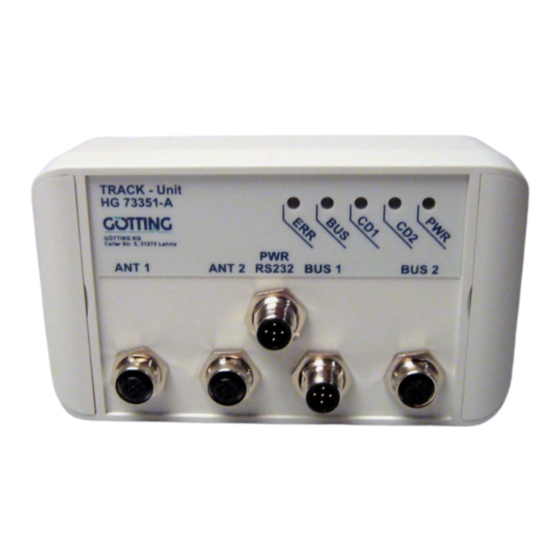
Mounting HG 7335xZA Mounting 2.1 Casing Casing interpreter HG 73350/HG 73351 Figure 1 2.2 Connectors All connectors are A-coded M12 panel plugs/jacks. 2.2.1 Antenna Sockets on the Interpreter The steering antennas are connected via a 1:1 cable to the corresponding 4-pin A- coded M12 panel jack. -
Page 7: Can Bus (Hg 73350)
Mounting HG 7335xZA 2.2.2 CAN Bus (HG 73350) The CAN bus is connected to the device via two 5-pin A-coded M12 connectors male/ female (see „Casing interpreter HG 73350/HG 73351“ on page 6.). There they can be found as BUS1 and BUS2, which are allocated as follows: Signal +24 V CAN_H... -
Page 8: Power Supply And Serial Interface
Mounting HG 7335xZA 2.2.4 Power supply and serial interface Here a 5-pin A-coded M12 panel plug is used, in Figure 1 referred to as PWR RS232. Signal Annotation +24 V Serial RS 232 data output Serial RS 232 data input Pin allocation of power supply and serial interface Table 5 This connection serves as the power supply. -
Page 9: Commissioning
Commissioning HG 7335xZA Commissioning After mounting or changing the antennas, a position calibration is recommended. Please see chapter 5.1.2 on page 14 and 6.5.4.18 on page 35. The position calibration has to be carried out for each antenna individually. NOTE! Only by processing this position calibration the interpreter is able to calculate and display the deviation scaled to mm. -
Page 10: Hardware
Hardware HG 7335xZA Hardware The casing of the interpreter is made of plastic. All wires etc. can be connected via M12 connectors on the front panel. The input signals (two per antenna) are amplified, filtered with an adjustable band filter (frequency input, see Figure 13 on page 42) and rectified synchronously. -
Page 11: The Control Leds
Hardware HG 7335xZA As in this range the DC offsets of the channels have to be compensated, a range of about 16000 resp. ±8000 units is usable. Further information may be found in chapter 6 on page 20 (CAN Bus) resp. chapter 7 on page 38 (Profibus). 4.4 The Control LEDs On the front panel a group of 5 LEDs can be found. -
Page 12: Software
Software HG 7335xZA Software 5.1 Monitor program The terminal (PC with the terminal program) has to be connected to the interpreter us- ing the socket in the middle (power supply and serial interface). The parameters for the serial interface are: ... -
Page 13: Table 6 Meaning Of The Possible Values In The Status Output
Software HG 7335xZA The first two lines represent the input. S1, S2, D1, D2 The values for S1, D1, S2, and D2 are each the sum of the 16 samplings. The range for the sum voltage is 0 to 16383 and for the difference voltage -8192 to +8191. X1, X2 X1 and X2 present the calculated values for the collateral deviation of the antennas above the guide wire in a range from -255 to +255 in mm. -
Page 14: Antenna Menu
Software HG 7335xZA 44,0,-15,9627,-3335,-256,50 44,0,-17,9626,-3333,-256,51 In this example the first number “44“ presents the current status of the device (here: threshold 2 exceeded), then Us1= 0 and Ud1= 17, followed by Us2= 9626 and Ud2= -3333. The last displayed numbers show the collateral deviations for antenna 1 and antenna 2. -
Page 15: Figure 6 Screenshot: Calibration Menu Antenna 1
Software HG 7335xZA starts the calibration of the distance output. Now the corresponding antenna has to be moved in an area of ±2x height over the guide wire. For the calibration a 10 kHz wire frequency is recommended as the frequency compensation is also referred to this frequency. -
Page 16: Can Menu (Hg 73350)
Software HG 7335xZA 5.1.3 CAN menu (HG 73350) You can find general information about the CAN Bus and the corresponding terms in chapter 6 on page 20. The CAN menu is made up as follows: X1: -256 X2: -256 Status: 0x00 Bus online Operational Last Err: 0000... -
Page 17: Profibus-Menu (Hg 73351)
Software HG 7335xZA is the time of the cycle of the PDO_2 transmission. If both values are 0, PDO_2 will no be transmitted. changes the so called Heartbeat time. At the chosen interval of this cycle time a control message is sent. If the time equals 0 no message is sent. ... -
Page 18: Switching To Different Environment Parameters
Software HG 7335xZA 5.2 Switching to different environment parameters The interpreter can also be used in combination with tracking systems which have an- other guide wire current or another reading height. Minor changes in the surrounding of the device (e.g. guide wire current between 35mA and 100mA at the same reading height) are compensated by the dynamic range of the device. -
Page 19: Figure 10 Screenshot: Firmware Upload
Software HG 7335xZA Now wait until the deletion of the flash memory is getting confirmed with <R>. Then choose the menu <Transmisson> <Send Text file> in Hyperterminal and enter the name of the software which should be programmed. The progress of the program- ming is displayed by <.>... -
Page 20: Can Interface (Hg 73350)
CAN Interface (HG 73350) HG 7335xZA CAN Interface (HG 73350) The node ID and the transfer rate have to be selected by using the serial monitor (de- scribed in section 5.1 on page 12) or the corresponding SDOs. The measured values of the system are transmitted via two so called TxPDOs. They can be parametrized using the SDOs. -
Page 21: Table 8 Pdo Operation Modes
CAN Interface (HG 73350) HG 7335xZA Operation Mode Explanation Cyclic every n‘th Sync telegram data is transmitted Acyclic transmits if an event has occurred since the last Sync tele- gram Synchronous data is transmitted after a Sync telegram is received Asynchronous data is transmitted event-driven solely upon request via a Remote Frame... -
Page 22: Description Of The Process Data Objects (Pdos)
CAN Interface (HG 73350) HG 7335xZA Name Meaning Stopped only network management service can be executed Pre-Operational full configuration possible, PDOs are not transmitted Operational full configuration possible, PDOs are transmitted CANopen® operation states Table 11 NOTE! Please observe that a CAN Identifier (for CANopen® the combi- nation of a CAN Identifier and Node Identifier) always has to be unique! 6.2 Description of the process data objects (PDOs) -
Page 23: Pdo_2
CAN Interface (HG 73350) HG 7335xZA The meaning of the status bits is determined as follows: Bit no. Value Meaning 0x80 Us1 exceeds chosen threshold for channel 1 0x40 Us2 exceeds chosen threshold for channel 2 0x20 Toggle-Bit, changes its status after each transmission of PDO_1 0x10 calibration is active 0x08... -
Page 24: Receiving Objects
CAN Interface (HG 73350) HG 7335xZA 6.2.2 Receiving objects The frequency of the wires can also be changed using a non-cyclical receiving PDO. Additionally, the RPDO can be deactivated/activated by setting/deleting the highest bit in the corresponding PDO-COB identifier [1400,01]. The RPDO is expected on identifier 0x200 + node address. -
Page 25: Object Directory
CAN Interface (HG 73350) HG 7335xZA Name Number Meaning SDO_ABORT_UNSUPPORTED 0x06010000 non-supported access to an object SDO_ABORT_READONLY 0x06010001 write access to read only object SDO_ABORT_NOT_EXISTS 0x06020000 object is not implemented SDO_ABORT_TRANSFER 0x08000020 During saving/loading of parameters the signature “load“ or “save“ has not been used. When calling calibration. - Page 26 CAN Interface (HG 73350) HG 7335xZA Communication specific entries located from 0x1000 to 0x1FFF Index Subindex Access Content EEProm 0x1011 Number of entries of Restore Default Parameter Restore Default all Restore Default Communication Parameter Restore Default Manufacture Parameter 0x1017 Producer Heartbeat Time 0x1018 Number of entries of Identity Object Vendor ID...
-
Page 27: Manufacturer Entries
CAN Interface (HG 73350) HG 7335xZA Communication specific entries located from 0x1000 to 0x1FFF Index Subindex Access Content EEProm 0x1A01 Number of Objects mapped to Transmit PDO_2 Specification of Appl. Object 1 Specification of Appl. Object 2 Specification of Appl. Object 3 Specification of Appl. -
Page 28: Standard Device Profile
CAN Interface (HG 73350) HG 7335xZA 6.5.3 Standard device profile When applying “Restore All“ the node ID is set to 1 and the baud rate to 125 Kbaud. Standard device profile from 0x6000 on Index Subindex Access Content 0x6000 Number of 8 Bit Digital Inputs System status 0x6401 Number of 16 Bit analog Inputs... -
Page 29: Cob-Id Sync Message
CAN Interface (HG 73350) HG 7335xZA 6.5.4.3 COB-ID SYNC message Index Sub Index Name Format Attr. Default Meaning 0x1005 COB-ID Unsigned 32 0x80000080 Sync Consumer, SYNC Sync ID = 0x80 CAN: COB-ID SYNC message Table 24 6.5.4.4 Device Name Index Subindex Name Format... -
Page 30: Restore Default Parameter
CAN Interface (HG 73350) HG 7335xZA By writing the signature “save“ in ASCII code (hex-Code: 0x65766173) or “evas“ (hex- Code: 0x73617665) on sub index 1 the current parameters are not quick saved. A suc- cesful save procedure will be confirmed after ca. 400 ms by the TxSDO (1st byte = 0x80). -
Page 31: Identity Object
CAN Interface (HG 73350) HG 7335xZA 6.5.4.10 Identity Object Index Sub Index Name Format Attr. Default Meaning 0x1018 Identity Unsigned 8 0x03 number of sub Object indexes Vendor ID Unsigned 32 0x00000202 manufacturer number, deter- mined by CiA Product Unsigned 32 0x00073350 name of the Code... -
Page 32: Transmit Pdo_1 Parameter
CAN Interface (HG 73350) HG 7335xZA 6.5.4.13 Transmit PDO_1 Parameter Index Sub Index Name Format Attr. Default Meaning 0x1800 TxPDO_1 Unsigned 8 0x04 number of sub Parameter indexes COB ID Unsigned 32 0x40000180 PDO_1 valid, ID + Node-ID = 0x180 + Node- Transmis- Unsigned 8 Asynchronous... -
Page 33: Mapping Txpdo_1
CAN Interface (HG 73350) HG 7335xZA 6.5.4.15 Mapping TxPDO_1 Index Sub Index Name Format Attr. Default Meaning 0x1A00 Number of Unsigned 8 0x03 number of sub mapped indexes objects 1st mapped Unsigned 32 0x60000108 mapped on Index object 0x6000,01 with 8 Bit length (Sta- tus) 2nd mapped... -
Page 34: Manufacture Parameter - Parameters Of The Antenna
CAN Interface (HG 73350) HG 7335xZA 6.5.4.17 Manufacture Parameter - parameters of the antenna Index Sub Index Name Format Attr. Default Meaning 0x2000 number of Unsigned 8 0x08 number of sub parameter indexes Frequency 1 Unsigned 16 10000 Frequency chan- nel 1 in Hz Frequency 2 Unsigned 16... -
Page 35: Manufacture Parameter - Calibration Of The Antenna
CAN Interface (HG 73350) HG 7335xZA 6.5.4.18 Manufacture parameter - calibration of the antenna Index Sub Index Name Format Attr. Default Meaning 0x2001 number of Unsigned 8 0x02 number of sub parameter indexes Start Ant-1 Unsigned 32 calibration Stop Ant-1 Unsigned 32 0x00000001 calibration... -
Page 36: Manufacture Parameter - Node Parameter
CAN Interface (HG 73350) HG 7335xZA 6.5.4.19 Manufacture parameter - node parameter Index Sub Index Name Format Attr. Default Meaning 0x2002 Number of Unsigned 8 0x02 number of sub Parameter indexes Node Baud- Unsigned 8 0x02 125 Kbaud, *) rate see Table 40 Node ID Unsigned 8... -
Page 37: Bit Digital Input (Transmitted In Txpdo 1)
CAN Interface (HG 73350) HG 7335xZA 6.5.4.20 8 Bit Digital Input (transmitted in TxPDO 1) Index Sub Index Name Format Attr. Default Meaning 0x6000 number of 8 Unsigned 8 0x01 number of 8 bit bit inputs inputs 8 bit digital Unsigned 8 system status / input... -
Page 38: Profibus Interface (Hg 73351)
Profibus Interface (HG 73351) HG 7335xZA Profibus Interface (HG 73351) The Node-ID has to be selected via the serial monitor described in section 5.1 on page 12. Using the GSD file 73351A0.GSD (see section D on page 45 in the appendix) two different configurations can be displayed, see below. -
Page 39: Troubleshooting
Troubleshooting HG 7335xZA Troubleshooting The following table contains a list of errors that might occur. For each error, a symptom description is given. In the third column you will find a description of how to locate and possibly correct the error. If you should not be able to correct an occurring error, please use the table below to locate the source of the error as exactly as possible (nature of malfunction, at which point of time did the error occur, etc.) before contacting us. -
Page 40: Technical Data
Technical Data HG 7335xZA Technical Data Interpreter for the Inductive Track Guidance of Vehicles HG 7335xZA Dimensions 160 mm x 90 mm x 50 mm Weight 400 g Protection class IP 64 Relative humidity at 25 95% (without bedewing) Operating temperature C to +50 Storage temperature C to +70... -
Page 41: Appendix
Appendix HG 7335xZA 10 Appendix Block Diagrams 4-25kHz 40Hz RS 232 µP 200kHz-1,25MHz Block diagram HG 73350 (CAN-Bus) Figure 11 4-25kHz 40Hz RS 232 µP Profibus 200kHz-1,25MHz Block diagram 73351 (Profibus) Figure 12 English, Revision 03, Date: 20.11.2015... -
Page 42: B Diagrams
Appendix HG 7335xZA Diagrams Frequency response interpreter 73350ZA + antenna 19200Z(Y)C Figure 13 Frequency response output compensated) Figure 14 English, Revision 03, Date: 20.11.2015... -
Page 43: Figure 15 Band Filter Characteristics At 5 Khz (Q=20)
Appendix HG 7335xZA Band filter characteristics at 5 kHz (Q=20) Figure 15 Band filter characteristics at 10 kHz (Q=22) Figure 16 English, Revision 03, Date: 20.11.2015... -
Page 44: Figure 17 Band Filter Characteristics At 15 Khz (Q=21)
Appendix HG 7335xZA Band filter characteristics at 15 kHz (Q=21) Figure 17 Band filter characteristics at 20 kHz (Q=22) Figure 18 English, Revision 03, Date: 20.11.2015... -
Page 45: C Electronic Data Sheet (Esd File, Hg 73350)
Appendix HG 7335xZA Band filter characteristics at 25 kHz (Q=28) Figure 19 Electronic Data Sheet (ESD File, HG 73350) You can find the latest version of the ESD file for the CAN configuration for download from our homepage at http://www.goetting-agv.com/components/7335x GSD File (HG 73351) You can find the latest version of the GSD file for the Profibus configuration for down- load from our homepage at http://www.goetting-agv.com/components/7335x. -
Page 46: List Of Figures
List of figures HG 7335xZA 11 List of figures Figure 1 Casing interpreter HG 73350/HG 73351 ..........6 Figure 2 Position of the LEDs................11 Figure 3 Screenshot: Main menu of the monitor program (HG 73350 with CAN Bus)....................12 Figure 4 Screenshot: Main menu of the monitor program (HG 73351 with Profi- bus).................... -
Page 47: List Of Tables
List of tables HG 7335xZA 12 List of tables Table 1 Variant Overview ................5 Table 2 Pin allocation antenna sockets ............6 Table 3 Pin allocation CAN bus ..............7 Table 4 Pin allocation Profibus............... 7 Table 5 Pin allocation of power supply and serial interface ......8 Table 6 Meaning of the possible values in the status output....... - Page 48 List of tables HG 7335xZA Table 34 CAN: Transmit PDO_1 Parameter ........... 32 Table 35 CAN: Transmit PDO_2 Parameter ........... 32 Table 36 CAN: Mapping TxPDO_1 ..............33 Table 37 CAN: Mapping TxPDO_2 ..............33 Table 38 CAN: Manufacture Parameter - parameters of the antenna ... 34 Table 39 CAN: Manufacture Parameter - calibration of the antenna.....
-
Page 49: Basic Information For Reading This Manual
Basic Information for Reading this Manual HG 7335xZA 13 Basic Information for Reading this Manual In documentations of Götting KG the following symbols and assignments were used at the time of printing this manual: Security advices have the following symbols, depending on the emphasis and the degree of exposure: NOTE! ATTENTION! -
Page 50: Copyright And Terms Of Liability
Copyright and Terms of Liability HG 7335xZA 14 Copyright and Terms of Liability 14.1 Copyright This manual is protected by copyright. All rights reserved. Violations are subject to pe- nal legislation of the Copyright. 14.2 Exclusion of Liability Any information given is to be understood as system description only, but is not to be taken as guaranteed features.
Need help?
Do you have a question about the HG 7335 ZA Series and is the answer not in the manual?
Questions and answers