Sign In
Upload
Manuals
Brands
Gotting Manuals
Media Converter
HG 73350ZA
Gotting HG 73350ZA Manuals
Manuals and User Guides for Gotting HG 73350ZA. We have
3
Gotting HG 73350ZA manuals available for free PDF download: Device Description, Manual
Gotting HG 73350ZA Manual (50 pages)
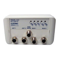
Interpreter for the Inductive Track Guidance of Vehicles, For the connection of 2 antennas Interfaces: CANopen HG G-73350ZA & Profibus HG G-73351ZA
Brand:
Gotting
| Category:
Media Converter
| Size: 2 MB
Table of Contents
Table of Contents
3
About this Document
5
Function
5
Symbols
5
Chapter 13 : List of Tables
7
Introduction
7
Components
7
Variant Overview
7
Table 1 Variant Overview
7
Mounting
8
Antenna Sockets on the Interpreter
8
Casing
8
Connectors
8
46 Chapter 46 46 Chapter 12: List of Figures
8
Figure 1 Casing Interpreter HG G-73350/HG G-73351
8
Table 2 Pin Allocation Antenna Sockets, Connectors ANT1 and ANT2
8
CAN Bus (HG G-73350)
9
Profibus (HG G-73351)
9
Table 3 Pin Allocation CAN Bus, Connectors BUS1 and BUS2
9
Table 4 Pin Allocation Profibus, Connectors BUS1 and BUS2
9
Power Supply and Serial Interface
10
Table 5 Pin Allocation of Power Supply and Serial Interface, Connector PWR / RS232
10
Commissioning
11
Hardware
12
Monitoring
12
Presettings
12
Processing the Signal
12
CAN Bus (HG G-73350)
13
Figure 2 Position of the Leds
13
Profibus (HG G-73351)
13
The Control Leds
13
Software
14
Connection to a PC Via the Serial Interface
14
Figure 3 Connection Example: Connection to the Serial Interface of a PC
14
Table 6 Transmission Parameters of the Serial RS 232 Interface
14
Terminal Program
14
Figure 4 Screenshot: Main Menu of the Monitor Program (HG G-73350 with CAN Bus)
15
Figure 5 Screenshot: Main Menu of the Monitor Program (HG G-73351 with Profibus)
15
Main Menu
15
Monitor Program
15
Table 7 Meaning of the Possible Values in the Status Output
16
Antenna Menu
17
Figure 6 Screenshot: Antenna Menu
17
CAN Menu (HG G-73350)
18
Figure 7 Screenshot: Calibration Menu Antenna 1
18
Figure 8 Screenshot: CAN Menu (HG G-73350)
18
Profibus-Menu (HG G-73351)
19
Figure 9 Screenshot: Profibus-Menu (HG G-73351)
20
Switching to Different Environment Parameters
20
Updating the Firmware
20
Figure 10 Screenshot: Firmware Update
21
Figure 11 Screenshot: Firmware Upload
21
CAN Interface (HG G-73350)
22
Definition of the Terms CAN and Canopen
22
Table 8 Parameters PDO Operation Mode
22
Table 10 Definition of Terms Can/Canopen
23
Table 11 Bit and Byte Order
23
Table 12 Canopen® Operation States
23
Table 9 PDO Operation Modes
23
Description of the Process Data Objects (Pdos)
24
Pdo_1
24
Table 13 CAN: Displayed Numbers for PDO_1
24
Table 14 CAN: Meaning of the Status Bits
24
Transmission Objects
24
Table 15 CAN: Calculation of Negative Deviation Values (Example: Maximum)
25
Table 16 CAN: Calculation of Positive Deviation Values (Example: Maximum)
25
Table 17 CAN: Deviation Value Output for Loss of Wire
25
Table 18 CAN: Example Values for the Deviation Value Output
25
Pdo_2
26
Receiving Objects
26
Table 19 CAN: Displayed Numbers for PDO_2
26
Table 20 Examples for the Conversion in PDO_2
26
Table 21 CAN: Displayed Numbers for RPDO
26
Heartbeat
27
Object Directory
27
Table 22 CAN: Heartbeat Device Statuses
27
Table 23 CAN: SDO Error Codes
27
Writing on Service Data Objects (Sdos)
27
Communication Specific Entries
28
Table 24 CAN: Overview of Object Directory, Communication Specific Entries between 0X1000 and
28
Manufacturer Entries
29
Table 25 CAN: Overview of Object Directory, Manufacture Specific Entries from 0X2000 on
29
Canopen Object Dictionary
30
COB-ID SYNC Message
30
Device Type
30
Error Register
30
Standard Device Profile
30
Table 26 CAN: Overview Object Directory, Standardized Device Profile from 0X6000 on
30
Table 27 CAN: Device Type
30
Table 28 CAN: Error Register
30
Table 29 CAN: COB-ID SYNC Message
30
Device Name
31
Hardware Version
31
Restore Default Parameter
31
Save Parameter
31
Software Version
31
Table 30 CAN: Device Name
31
Table 31 CAN: Hardware Version
31
Table 32 CAN: Software Version
31
Table 33 CAN: Save Parameter
31
Table 34 CAN: Restore Default Parameter
31
Identity Object
32
Mapping RPDO_1
32
Producer Heartbeat Time
32
Receive PDO Parameter
32
Table 35 CAN: Producer Heartbeat Time
32
Profibus Interface (HG G-73351)
38
Table 50 Format of the 5 Profibus Input Bytes
38
Table 51 Profibus: Meaning of the Profibus Status Bits
38
Table 52 Profibus: Setting the Wire Frequencies
38
Table 53 Troubleshooting
39
Troubleshooting
39
48 Chapter 48 48 Chapter 13: List of Tables
32
Table 36 CAN: Identity Object
32
Table 37 CAN: Receive PDO Parameter
32
Table 38 CAN: Mapping RPDO_1
32
Mapping Txpdo_1
33
Table 39 CAN: Transmit PDO_1 Parameter
33
Table 40 CAN: Transmit PDO_2 Parameter
33
Table 41 CAN: Mapping Txpdo_1
33
Transmit PDO_1 Parameter
33
Transmit PDO_2 Parameter
33
Manufacture Parameter - Parameters of the Antenna
34
Mapping Txpdo_2
34
Table 42 CAN: Mapping Txpdo_2
34
Table 43 CAN: Manufacture Parameter - Parameters of the Antenna
34
Manufacture Parameter - Calibration of the Antenna
35
Table 44 CAN: Manufacture Parameter - Calibration of the Antenna
35
Bit Digital Input (Transmitted in Txpdo 1)
36
Manufacture Parameter - Node Parameter
36
Table 45 CAN: Coding of the Node Baudrate
36
Table 46 CAN: Coding of the Node Config Byte
36
Table 47 CAN: Manufacture Parameter - Node Parameter
36
Table 48 CAN: 8 Bit Digital Input (Transmitted in Txpdo 1)
36
Bit Analog Inputs (Transmitted in Txpdo 1 und Txpdo 2)
37
Table 49 CAN: 16 Bit Analog Inputs (Transmitted in Txpdo 1 und Txpdo 2)
37
Table 54 Technical Data HG G-7335Xza
40
Technical Data
40
Appendix
41
A Block Diagrams
41
Figure 12 Block Diagram HG G-73350 (CAN-Bus)
41
Figure 13 Block Diagram HG G-73351 (Profibus)
41
B Diagrams
42
Figure 14 Frequency Response Interpreter HG G-73350ZA + Antenna HG G-19200Z(Y)C
42
Figure 15 Frequency Response Output Compensated)
42
Figure 16 Band Filter Characteristics at 5 Khz (Q=20)
43
Figure 17 Band Filter Characteristics at 10 Khz (Q=22)
43
Figure 18 Band Filter Characteristics at 15 Khz (Q=21)
44
Figure 19 Band Filter Characteristics at 20 Khz (Q=22)
44
C Electronic Data Sheet (ESD File, HG G-73350)
45
DGSD File (HG G-73351)
45
Figure 20 Band Filter Characteristics at 25 Khz (Q=28)
45
12: List of Figures List of Figures
46
List of Figures
46
List of Tables
47
Copyright and Terms of Liability
49
Copyright
49
Exclusion of Liability
49
Trade Marks and Company Names
49
Advertisement
Gotting HG 73350ZA Device Description (50 pages)
Interpreter for the Inductive Track Guidance of Vehicles
Brand:
Gotting
| Category:
GPS
| Size: 0 MB
Table of Contents
Table of Contents
2
1 Introduction
5
Variant Overview
5
Components
5
Table 1 Variant Overview
5
2 Mounting
6
Casing
6
Connectors
6
Antenna Sockets on the Interpreter
6
Figure 1 Casing Interpreter HG 73350/HG 73351
6
Table 2 Pin Allocation Antenna Sockets
6
CAN Bus (HG 73350)
7
Profibus (HG 73351)
7
Table 3 Pin Allocation CAN Bus
7
Table 4 Pin Allocation Profibus
7
Power Supply and Serial Interface
8
Table 5 Pin Allocation of Power Supply and Serial Interface
8
3 Commissioning
9
4 Hardware
10
Monitoring
10
Presettings
10
Processing the Signal
10
The Control Leds
11
CAN Bus (HG 73350)
11
Figure 2 Position of the Leds
11
Profibus (HG 73351)
11
5 Software
12
Monitor Program
12
Figure 3 Screenshot: Main Menu of the Monitor Program
12
Figure 4 Screenshot: Main Menu of the Monitor Program
12
Main Menu
12
Table 6 Meaning of the Possible Values in the Status Output
13
Antenna Menu
14
Figure 5 Screenshot: Antenna Menu
14
Figure 6 Screenshot: Calibration Menu Antenna 1
15
CAN Menu (HG 73350)
16
Figure 7 Screenshot: CAN Menu (HG 73350)
16
Figure 8 Screenshot: Profibus-Menu (HG 73351)
17
Profibus-Menu (HG 73351)
17
Switching to Different Environment Parameters
18
Updating the Firmware
18
Figure 9 Screenshot: Firmware Update
18
Figure 10 Screenshot: Firmware Upload
19
6 CAN Interface (HG 73350)
20
Definition of the Terms CAN and Canopen
20
Table 7 Parameters PDO Operation Mode
20
Table 8 PDO Operation Modes
21
Table 9 Definition of Terms Can/Canopen
21
Table 10 Bit and Byte Order
21
Description of the Process Data Objects (Pdos)
22
Pdo_1
22
Table 11 Canopen® Operation States
22
Table 12 CAN: Displayed Numbers for PDO_1
22
Transmission Objects
22
Pdo_2
23
Table 13 CAN: Meaning of the Status Bits
23
Table 14 CAN: Displayed Numbers for PDO_2
23
Table 15 Examples for the Conversion in PDO_2
23
Receiving Objects
24
Heartbeat
24
Writing on Service Data Objects (Sdos)
24
Table 16 CAN: Displayed Numbers for RPDO
24
Table 17 CAN: Heartbeat Device Statuses
24
Object Directory
25
Communication Specific Entries
25
Table 18 CAN: SDO Error Codes
25
Table 19 CAN: Overview of Object Directory, Communication Specific Entries
25
Manufacturer Entries
27
Table 20 CAN: Overview of Object Directory, Manufacture Specific Entries from 0X2000 on
27
Canopen Object Dictionary
28
Device Type
28
Error Register
28
Standard Device Profile
28
Table 21 CAN: Overview Object Directory, Standardized Device Profile from
28
Table 22 CAN: Device Type
28
Table 23 CAN: Error Register
28
COB-ID SYNC Message
29
Device Name
29
Hardware Version
29
Save Parameter
29
Software Version
29
Table 24 CAN: COB-ID SYNC Message
29
Table 25 CAN: Device Name
29
Table 26 CAN: Hardware Version
29
Table 27 CAN: Software Version
29
Table 28 CAN: Save Parameter
29
Producer Heartbeat Time
30
Restore Default Parameter
30
Table 29 CAN: Restore Default Parameter
30
Table 30 CAN: Producer Heartbeat Time
30
Identity Object
31
Mapping RPDO_1
31
Receive PDO Parameter
31
Table 31 CAN: Identity Object
31
Table 32 CAN: Receive PDO Parameter
31
Table 33 CAN: Mapping RPDO_1
31
Table 34 CAN: Transmit PDO_1 Parameter
32
Table 35 CAN: Transmit PDO_2 Parameter
32
Transmit PDO_1 Parameter
32
Transmit PDO_2 Parameter
32
Mapping Txpdo_1
33
Mapping Txpdo_2
33
Table 36 CAN: Mapping Txpdo_1
33
Table 37 CAN: Mapping Txpdo_2
33
Manufacture Parameter - Parameters of the Antenna
34
Table 38 CAN: Manufacture Parameter - Parameters of the Antenna
34
Manufacture Parameter - Calibration of the Antenna
35
Table 39 CAN: Manufacture Parameter - Calibration of the Antenna
35
Manufacture Parameter - Node Parameter
36
Table 40 CAN: Coding of the Node Baudrate
36
Table 41 CAN: Coding of the Node Baudrate
36
Table 42 CAN: Manufacture Parameter - Node Parameter
36
Bit Analog Inputs (Transmitted in Txpdo 1 und Txpdo 2)
37
Bit Digital Input (Transmitted in Txpdo 1)
37
Table 43 CAN: 8 Bit Digital Input (Transmitted in Txpdo 1)
37
7 Profibus Interface (HG 73351)
38
Table 45 Format of the 5 Profibus Input Bytes
38
Table 46 Profibus: Meaning of the Profibus Status Bits
38
Table 47 Profibus: Setting the Wire Frequencies
38
8 Troubleshooting
39
Table 48 Troubleshooting
39
9 Technical Data
40
Table 49 Technical Data Interpreter for the Inductive Track Guidance of Vehi- Cles HG 7335Xza
40
10 Appendix
41
A Block Diagrams
41
Figure 11 Block Diagram HG 73350 (CAN-Bus)
41
Figure 12 Block Diagram 73351 (Profibus)
41
B Diagrams
42
Figure 13 Frequency Response Interpreter 73350ZA + Antenna 19200Z(Y)C
42
Figure 14 Frequency Response Output Compensated)
42
Figure 15 Band Filter Characteristics at 5 Khz (Q=20)
43
Figure 16 Band Filter Characteristics at 10 Khz (Q=22)
43
Figure 17 Band Filter Characteristics at 15 Khz (Q=21)
44
Figure 18 Band Filter Characteristics at 20 Khz (Q=22)
44
C Electronic Data Sheet (ESD File, HG 73350)
45
DGSD File (HG 73351)
45
Figure 19 Band Filter Characteristics at 25 Khz (Q=28)
45
List of Figures
46
12 List of Tables
47
13 Basic Information for Reading this Manual
49
14 Copyright and Terms of Liability
50
Copyright
50
Exclusion of Liability
50
Gotting HG 73350ZA Device Description (45 pages)
For Inductive Guidance Of Vehicles, CAN-Open
Brand:
Gotting
| Category:
Microphone system
| Size: 1 MB
Table of Contents
Table of Contents
2
1 Essential Information for Reading this Manual
4
2 Introduction
5
3 Mounting
6
CAN Bus
7
4 Commissioning
8
5 Hardware
9
The Control LED
10
6 Software
11
Antenna Menu
12
CAN Menu
14
Changing the Surrounding
16
7 CAN Interface
18
Receiving Objects
19
Heartbeat
20
Object Directory
21
Manufacturer Entries
23
Standard Device Profile
24
Canopen Object Dictionary
25
Hardware Version
26
Producer Heartbeat Time
27
Mapping RPDO_1
28
Transmit PDO_2 Parameter
29
Mapping Txpdo_2
30
Manufacture Parameter - Parameters of the Antenna
31
Manufacture Parameter - Calibration of the Antenna
32
Manufacture Parameter - Node Parameter
33
Bit Digital Input (Transmitted in Txpdo 1)
34
8 Troubleshooting
35
9 Technical Data
36
10 Appendix
37
Diagrams
38
Electronic Data Sheet (EDS File)
41
11 List of Figures
42
12 List of Tables
43
13 Copyright and Terms of Liability
45
Advertisement
Advertisement
Related Products
Gotting HG 73351ZA
Gotting HG G-71912-A
Gotting HG 73350
Gotting HG 7335 ZA Series
Gotting HG 73840ZB
Gotting HG 76342-A
Gotting HG 71912-A
Gotting HG 71451-A
Gotting HG 71453-A
Gotting HG 71450-A
Gotting Categories
Antenna
GPS
Accessories
Controller
Marine Radio
More Gotting Manuals
Login
Sign In
OR
Sign in with Facebook
Sign in with Google
Upload manual
Upload from disk
Upload from URL