Table of Contents
Advertisement
Quick Links
Guide Wire
Track-Unit
HG G-7335xZB
Interpreter for the Inductive Track Guidance of Vehicles for the
connection of 2 antennas – Interfaces:
CANopen® HG G-73350ZB / Profibus HG G-73351ZB
English, Revision 07
Date: 10.05.2023
Dev. by: WM
Author(s): RAD / MN
Innovation through Guidance
www.goetting-agv.com
Advertisement
Chapters
Table of Contents

Related Manuals for Gotting HG G-73350ZB


Summary of Contents for Gotting HG G-73350ZB
- Page 1 Guide Wire Track-Unit HG G-7335xZB Interpreter for the Inductive Track Guidance of Vehicles for the connection of 2 antennas – Interfaces: CANopen® HG G-73350ZB / Profibus HG G-73351ZB English, Revision 07 Date: 10.05.2023 Dev. by: WM Author(s): RAD / MN Innovation through Guidance www.goetting-agv.com...
- Page 2 Overview Basic characteristics of the Track-Units HG G-73350ZB (CAN bus) and HG G-73351ZB (Profibus) Interpreter for inductive track guidance systems For the connection of 2 guidance antennas 2 identical channels with independent filter frequency setting Monitoring of connected antennas for correct operation and wire breakage ...
-
Page 3: Table Of Contents
Table of Contents Contents About this Document..................5 Validity ................................5 1.1.1 Target Group............................5 1.1.2 Other Applicable Documents......................5 Declaration of Conformity (only HG G-73350) ................5 Presentation of Information........................6 1.3.1 Warning Notices.............................6 1.3.2 Symbols..............................7 Safety Instructions ..................8 Intended Use..............................8 Improper Use ..............................8 Qualification of the Users........................9 Operating Conditions ..........................9 General Safety Instructions.........................10 Obligations of the Operator.........................10... - Page 4 Table of Contents 8.2.2 Receiving Objects ..........................32 Heartbeat ..............................33 Writing on Service Data Objects (SDOs) ..................33 Object Directory............................33 8.5.1 Communication specific entries....................34 8.5.2 Manufacturer entries .........................35 8.5.3 Standard device profile ........................36 8.5.4 CANopen Object Dictionary ......................36 8.5.4.1 Device Type ............................36 8.5.4.2 Error Register ...........................36 8.5.4.3...
-
Page 5: About This Document
About this Document – Chapter 1 About this Document 1.1 Validity This device description applies to the interpreter HG G-7335xZB. It contains information on correct mounting, electrical installation, commissioning, operation, maintenance and fault rectification. This device description refers to devices from firmware as specified in section 3.1 on page 12. -
Page 6: Presentation Of Information
Chapter 1 – About this Document You can request the EU declaration of conformity from Götting KG or download it from the following address https://www.goetting-agv.com/components/7335x 1.3 Presentation of Information For you to be able to use your product simply and safely this device description uses consistent warning notices, symbols, terms and abbreviations. -
Page 7: Symbols
About this Document – Chapter 1 1.3.2 Symbols In this device description the following symbols and formatting are used: If this information is ignored the product may not be operated in an optimal way. Indicates one or more links to the Internet. –... -
Page 8: Safety Instructions
Chapter 2 – Safety Instructions Safety Instructions This product has been manufactured in accordance with the generally recognized rules of technology. Nevertheless, there is a risk of personal injury and material dam- age if you do not observe this chapter and the safety instructions in this documen- tation. -
Page 9: Qualification Of The Users
Safety Instructions – Chapter 2 Improper use includes: The use of the track guidance system in vehicles that are not equipped with safety devices for personal protection and safe detection of obstacles. Any departure from the lane or the appearance of a person or an obstacle in the danger area must be reliably detected at all times and immediate stopping of moving parts (e.g. -
Page 10: General Safety Instructions
Chapter 2 – Safety Instructions The nominal reading distance between antenna and wire depends on the antenna type and the wire current. In between antenna and guide wire there may be no metal. Non-conducting and non-shielding dirt on the roadway as well as water, oil, tar, earth, fog, snow and ice do not influence the positioning. - Page 11 Safety Instructions – Chapter 2 all components of the track guidance system is in a technically perfect condi- tion. The operator may not modify or convert Götting systems, devices and components without authorization. Device Description HG G-7335xZB | English, Revision 07 | Date: 10.05.2023...
-
Page 12: Introduction
HG 73351ZB Profibus This manual describes the hardware revision 73350ZA2 starting at firmware 73350A01.14 (HG G-73350ZB) resp. 73350YA2 with firmware 73351A01.00 (HG G- 73351ZB). 3.2 System Components At the time this manual was printed, the interpreter can be combined with the fol-... - Page 13 Introduction – Chapter 3 Cable for CAN-Bus Bus cable 2 pin or sensor cable 5 pin (incl. voltage supply), shielded, plug or socket, A-coded, max. length 30 m cable length influences max. baud rate, e.g. 2 pin bus cable, baud rate 1 MBit, max.
-
Page 14: Mounting
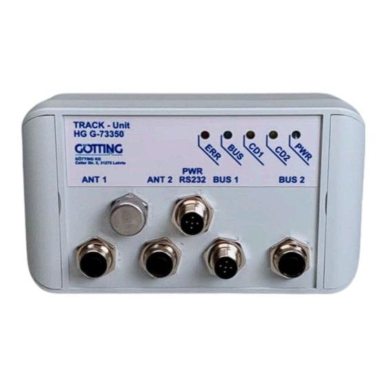
Chapter 4 – Mounting Mounting 4.1 Casing Dimensions Casing dimensions interpreter HG G-73350/HG G-73351 Figure 1 approx. 4.2 Connectors All connectors are M12 panel plugs/jacks, except for the B-coded Profibus connec- tors they are A-coded. The casings of all connectors are connected to the device GND (Pin 5 in Table 6 on page 16). -
Page 15: Can Bus (Hg G-73350)
Mounting – Chapter 4 These panel jacks provide connection to the antennas. It is irrelevant whether one or two antennas are connected. When using only one antenna, ANT1 or ANT2 can be chosen. The displaying of CD1/CD2 on the front panel (Siehe „Position of the LEDs“ auf Seite 19.) refers to the corresponding antenna input. -
Page 16: Power Supply And Serial Interface
Chapter 4 – Mounting The connectors of the inputs BUS1/BUS2 are connected in parallel, i.e. there is no input or output. If the interpreter is installed at the end of the bus line, a bus termi- nator has to be provided. Those terminators can be ordered from different manufac- turers and are available for most plugs and jacks. -
Page 17: Commissioning
Commissioning – Chapter 5 Commissioning After mounting or changing the antennas, a position calibration is recommended. Please see sections 7.3.2 on page 23 and 8.5.4.18 on page 42. The position calibra- tion has to be carried out for each antenna individually. Only by processing this position calibration the interpreter is able to calculate and display the deviation scaled to mm. -
Page 18: Hardware
Chapter 6 – Hardware Hardware The casing of the interpreter is made of plastic. All wires etc. can be connected via M12 connectors on the front panel. The input signals (two per antenna) are ampli- fied, filtered with an adjustable band filter (frequency input, see Figure 14 on page 49) and rectified synchronously. -
Page 19: The Control Leds
Hardware – Chapter 6 have to As in this range the DC offsets of the channels be compensated, a range of about 16000 resp. ±8000 units is usable. Further information may be found in chap- ter on page 28 (CAN Bus) resp. chapter on page 45 (Profibus). 6.4 The Control LEDs On the front panel a group of 5 LEDs can be found. -
Page 20: Software
Chapter 7 – Software Software 7.1 Connection to a PC via the Serial Interface The interpreter has a serial interface included in the 5 pin PWR RS232. This interface can be used for its diagnosis, configuration or a software update. A PC with a serial RS 232 interface is needed. -
Page 21: Monitor Program
Software – Chapter 7 7.3 Monitor Program Connect the PC to the interpreter and start the Terminal program.The monitor will start after pressing ‘m‘ or 7.3.1 Main Menu Depending to the variant the following menu appears: Screenshot: Main menu of the monitor program (HG G-73350 with CAN Bus) Figure 4 S2: 10816 D2: -4403... -
Page 22: Table 8 Meaning Of The Possible Values In The Status Output
Chapter 7 – Software Meaning of the possible values in the status output Table 8 Hex value Meaning 0x80 S1 has exceeded the set threshold for channel 1 0x40 S2 has exceeded the set threshold for channel 2 0x20 not connected 0x10 calibration in progress 0x08... -
Page 23: Antenna Menu
Software – Chapter 7 7.3.2 Antenna Menu In this chapter the sub menu for antenna 1 will be explained. The sub menu for an- tenna 2 is identical. Screenshot: Antenna menu Figure 6 S2: 10816 D2: -4403 X1:-256 mm X2: -50 mm Status: 0x40 (F)req 1 select [/Hz]:... -
Page 24: Can Menu (Hg G-73350)
Chapter 7 – Software Calibration Menu The calibration menu (here: antenna 1) is made up as follows: Screenshot: Calibration menu antenna 1 Figure 7 3780 3617 3133 4590 Status: 0xc0 Us1: 3795 Udl1: Udr1: 3645 shift Antenna 1 from -2*H to +2*H and press any key when ready During the calibration the maximum of the voltage is saved in . - Page 25 Software – Chapter 7 with the node address in a range from 1 to 127 can be chosen. by pressing one of the listed baudrates can be chosen, the function auto- baud is not implemented. PDO_1 ...
-
Page 26: Profibus Menu (Hg G-73351)
Chapter 7 – Software 7.3.4 rofibus Menu (HG G-73351) The specification of the Profibus telegrams is shown in chapter on page 45. The Pro- fibus menu is made up as follows: Screenshot: Profibus-Menu (HG G-73351) Figure 9 6453 X2: -256 Status: 0x80 Byte # Master-Input... -
Page 27: Figure 10 Screenshot: Firmware Update
Software – Chapter 7 The XON/XOFF flow control has to be activated! Start the interpreter‘s main menu (description see above) and choose (U)pdate firmware. Then enter the password On the screen the following image appears: Screenshot: Firmware update Figure 10 Please wait for 'R' and transfer Intel-Hex file as ASCII upload -------------- Flash Loader... -
Page 28: Can Interface (Hg G-73350)
Chapter 8 – CAN Interface (HG G-73350) CAN Interface (HG G-73350) The node ID and the transfer rate have to be selected by using the serial monitor (de- scribed in section 7.2 on page 20) or the corresponding SDOs. The measured values of the system are transmitted via two so called TxPDOs. They can be parametrized using the SDOs. -
Page 29: Table 10 Pdo Operation Modes
CAN Interface (HG G-73350) – Chapter 8 PDO operation modes Table 10 Operation Mode Explanation Cyclic every n‘th Sync telegram data is transmitted Acyclic transmits if an event has occurred since the last Sync tele- gram Synchronous data is transmitted after a Sync telegram is received Asynchronous data is transmitted event-driven solely upon request via a Remote Frame... -
Page 30: Description Of The Process Data Objects (Pdos)
Chapter 8 – CAN Interface (HG G-73350) 8.2 Description of the Process Data Objects (PDOs) 8.2.1 Transmission Objects The measured data are allocated to particular places in the PDO, a dynamical map- ping is not provided. The PDO mode can be set to cyclical, synchronous or a asyn- chronous. -
Page 31: Table 16 Can: Calculation Of Negative Deviation Values (Example: Maximum)
CAN Interface (HG G-73350) – Chapter 8 Directly after the MSB the 8-Bit representation of the deviation value (marked green in the below tables) does follow, while the remaining Bits of lower value are filled with 0. The internal deviation value in fact is a signed 9-bit number which has been shifted by 7 digits to the left, which equals a multiplication by 128 (2^7). -
Page 32: Pdo_2
Chapter 8 – CAN Interface (HG G-73350) 8.2.1.2 PDO_2 PDO_2 is sent with identifier 0x280 + node address. It contains exactly four 16bit words (left-aligned) in the order Us1, Ud1, Us2, Ud2. The synchronous identifier which is up to be received is 0x80. It can be read in index [1005,00]. CAN: displayed numbers for PDO_2 Table 20 Channel... -
Page 33: Heartbeat
CAN Interface (HG G-73350) – Chapter 8 8.3 Heartbeat The device supports the heartbeat mode. If a heartbeat time > 0 is set in the CAN menu the status of the device is sent to the identifier 0x700 + node address after the heartbeat timer has expired. -
Page 34: Communication Specific Entries
Chapter 8 – CAN Interface (HG G-73350) The object directory is divided into the following parts: 8.5.1 Communication specific entries CAN: overview of object directory, communication specific entries between 0x1000 Table 25 and 0x1FFF (part 1 of 2) Communication specific entries located from 0x1000 to 0x1FFF Index Subindex Access Content EEProm... -
Page 35: Manufacturer Entries
CAN Interface (HG G-73350) – Chapter 8 CAN: overview of object directory, communication specific entries between 0x1000 Table 25 and 0x1FFF (part 2 of 2) Communication specific entries located from 0x1000 to 0x1FFF Index Subindex Access Content EEProm 0x1801 0 Number of entries of Transmit PDO_2 COB-ID Transmission Type... -
Page 36: Standard Device Profile
Chapter 8 – CAN Interface (HG G-73350) CAN: overview of object directory, manufacture specific entries from 0x2000 on Table 26 (part 2 of 2) Manufacturer entries from 0x2000 on Index Subindex Access Content EEProm 0x2002 Number of Parameter Node Baudrate Node ID Node Config 8.5.3 Standard device profile... -
Page 37: Cob-Id Sync Message
CAN Interface (HG G-73350) – Chapter 8 8.5.4.3 COB-ID SYNC message CAN: COB-ID SYNC message Table 30 Index Sub Index Name Format Attr. Map Default Meaning 0x1005 00 COB-ID SYNC Unsigned 32 0x80000080 Sync Consumer, Sync ID = 0x80 8.5.4.4 Device Name CAN: Device Name Table 31 Index... -
Page 38: Restore Default Parameter
Chapter 8 – CAN Interface (HG G-73350) 8.5.4.8 Restore Default Parameter CAN: Restore Default Parameter Table 35 Index Sub Index Name Format Attr. Map Default Meaning 0x1011 00 Restore Unsigned 8 0x04 number of sub Parameter indexes Restore All Unsigned 32 RW 0x00000001 Restore All is possi- Restore Com- Unsigned 32 RW... -
Page 39: Receive Pdo Parameter
CAN Interface (HG G-73350) – Chapter 8 8.5.4.11 Receive PDO Parameter CAN: Receive PDO Parameter Table 38 Index Subindex Name Format Attr. Map Default Meaning 0x1400 00 RxPDO_1 Unsigned 8 number of sub Parameter indexes COB-ID Unsigned 32 0x40000200 RPDO valid, ID = + Node ID 0x200 + Node ID Transmission... -
Page 40: Transmit Pdo_2 Parameter
Chapter 8 – CAN Interface (HG G-73350) 8.5.4.14 Transmit PDO_2 Parameter CAN: Transmit PDO_2 Parameter Table 41 Index Sub Index Name Format Attr. Map Default Meaning 0x1801 00 TxPDO_2 Unsigned 8 0x04 number of sub Parameter indexes COB ID Unsigned 32 0x40000280 PDO_2 valid, ID = + Node-ID... -
Page 41: Mapping Txpdo_2
CAN Interface (HG G-73350) – Chapter 8 8.5.4.16 Mapping TxPDO_2 CAN: Mapping TxPDO_2 Table 43 Index Sub Index Name Format Attr. Map Default Meaning 0x1A01 00 number of Unsigned 8 0x04 number of sub indexes mapped objects 1st mapped Unsigned 32 RO 0x64010110 mapped on Index object 0x6401,01 with 16 Bit... -
Page 42: Manufacture Parameter - Calibration Of The Antenna
Chapter 8 – CAN Interface (HG G-73350) 8.5.4.18 Manufacture parameter - calibration of the antenna CAN: Manufacture Parameter - calibration of the antenna Table 45 Index Sub Index Name Format Attr. Map Default Meaning 0x2001 00 number of Unsigned 8 0x02 number of sub parameter... -
Page 43: Manufacture Parameter - Node Parameter
CAN Interface (HG G-73350) – Chapter 8 8.5.4.19 Manufacture parameter - node parameter CAN: Manufacture parameter - node parameter Table 46 Index Sub Index Name Format Attr. Map Default Meaning 0x2002 00 Number of Unsigned 8 RO 0x02 number of sub indexes Parameter Node Baud-rate Unsigned 8 RW 0x02... -
Page 44: Bit Analog Inputs (Transmitted In Txpdo 1 Und Txpdo 2)
Chapter 8 – CAN Interface (HG G-73350) 8.5.4.21 16 Bit Analog Inputs (transmitted in TxPDO 1 und TxPDO 2) CAN: 16 bit analog inputs (transmitted in TxPDO 1 und TxPDO 2) Table 50 Index Sub Index Name Format Attr. Map Default Meaning 0x6401 00 number of 16 Unsigned 8... -
Page 45: Profibus Interface (Hg G-73351)
Profibus Interface (HG G-73351) – Chapter 9 Profibus Interface (HG G-73351) The Node-ID has to be selected via the serial monitor described in section 7.2 on page 20. Using the GSD file 73351A0.GSD (see section 12.4 on page 52 in the ap- pendix) two different configurations can be displayed, see below. -
Page 46: Troubleshooting
Chapter 10 – Troubleshooting Troubleshooting The following table contains a list of errors that might occur. For each error, a symp- tom description is given. In the third column you will find a description of how to lo- cate and possibly correct the error. If you should not be able to correct an occurring error, please use the table below to locate the source of the error as exactly as possible (nature of malfunction, at which point of time did the error occur, etc.) before contacting us. -
Page 47: Technical Data
Technical Data – Chapter 11 Technical Data Technical Data HG G-7335xZB Table 55 Technical Data HG G-7335xZB Dimensions 160 mm x 90 mm x 50 mm Weight 400 g Protection class IP 64 Relative humidity at 25 C 95% (without bedewing) Operating temperature C to +50 Storage temperature... -
Page 48: Appendix
Chapter 12 – Appendix Appendix 12.1 Block Diagrams Block diagram HG G-73350 (CAN-Bus) Figure 12 4-25kHz 40Hz RS 232 µP 200kHz-1,25MHz Block diagram HG G-73351 (Profibus) Figure 13 4-25kHz 40Hz RS 232 µP Profibus 200kHz-1,25MHz Device Description HG G-7335xZB | English, Revision 07 | Date: 10.05.2023... -
Page 49: Diagrams
Appendix – Chapter 12 12.2 Diagrams Frequency response interpreter HG G-73350 + antenna HG G-19200Z(Y)C Figure 14 Frequency response output compensated) Figure 15 Device Description HG G-7335xZB | English, Revision 07 | Date: 10.05.2023... -
Page 50: Figure 16 Band Filter Characteristics At 5 Khz (Q=20)
Chapter 12 – Appendix Band filter characteristics at 5 kHz (Q=20) Figure 16 Band filter characteristics at 10 kHz (Q=22) Figure 17 Device Description HG G-7335xZB | English, Revision 07 | Date: 10.05.2023... -
Page 51: Figure 18 Band Filter Characteristics At 15 Khz (Q=21)
Appendix – Chapter 12 Band filter characteristics at 15 kHz (Q=21) Figure 18 Band filter characteristics at 20 kHz (Q=22) Figure 19 Band filter characteristics at 25 kHz (Q=28) Figure 20 Device Description HG G-7335xZB | English, Revision 07 | Date: 10.05.2023... -
Page 52: Electronic Data Sheet (Eds File, Hg G-73350)
Chapter 12 – Appendix 12.3 Electronic Data Sheet (EDS File, HG G-73350) You can find the latest version of the ESD file for the CAN configuration for download from our homepage. http://www.goetting-agv.com/components/7335x 12.4 GSD File (HG G-73351) You can find the latest version of the GSD file for the Profibus configuration for download from our homepage. -
Page 53: List Of Figures
List of Figures – Chapter 13 List of Figures Figure 1 Casing dimensions interpreter HG G-73350/HG G-73351...........14 Figure 2 Position of the LEDs........................19 Figure 3 Connection example: Connection to the serial interface of a PC......20 Figure 4 Screenshot: Main menu of the monitor program (HG G-73350 with CAN Bus)................................ -
Page 54: List Of Tables
Chapter 14 – List of Tables List of Tables Table 1 Hazard classification according to ANSI Z535.6-2006............. 6 Table 2 Variant Overview..........................12 Table 3 Pin allocation antenna sockets, connectors ANT1 and ANT2........14 Table 4 Pin allocation CAN bus, connectors BUS1 and BUS2.............15 Table 5 Pin allocation Profibus, connectors BUS1 and BUS2............15 Table 6... - Page 55 List of Tables – Chapter 14 Table 38 CAN: Receive PDO Parameter....................39 Table 39 CAN: Mapping RPDO_1 .......................39 Table 40 CAN: Transmit PDO_1 Parameter ...................39 Table 41 CAN: Transmit PDO_2 Parameter ...................40 Table 42 CAN: Mapping TxPDO_1......................40 Table 43 CAN: Mapping TxPDO_2......................41 Table 44 CAN: Manufacture Parameter - parameters of the antenna ........41 Table 45...
-
Page 56: Index
Chapter 15 – Index Index Validity..................5 Accessories ..................12 Cables..................12 EDS ......................52 ANT1 ....................14 Environment Parameters............26 ANT2 ....................14 EU Declaration of Conformity............ 6 Antenna Menu ................23 Exclusion of Liability..............58 Block Diagrams ................48 Firmware-Update ................26 BUS1 ....................15 Frequency response..............49 BUS2 ....................15 General Safety Instructions............10 Cables ....................12 Calibration Menu ................24... - Page 57 Index – Chapter 15 Interface..................45 Serial Interface ................20 Output Bytes................45 Transmission Parameters ..........20 Status Bits................45 Software....................20 Profibus Interface ................. 45 Symbols....................7 Profibus Menu ................26 System Components..............12 PWR ....................16 Target Group ..................5 Qualification of the Users.............9 Technical Data................47 Terminal Program .................20 trade marks..................58...
-
Page 58: Copyright And Terms Of Liability
Chapter 16 – Copyright and Terms of Liability Copyright and Terms of Liability 16.1 Copyright This manual is protected by copyright. All rights reserved. Violations are subject to penal legislation of the Copyright. 16.2 Exclusion of Liability Any information given is to be understood as system description only, but is not to be taken as guaranteed features. - Page 59 Copyright and Terms of Liability – Chapter 16 Device Description HG G-7335xZB | English, Revision 07 | Date: 10.05.2023...
- Page 60 Innovation through Guidance Götting KG Celler Str. 5 | D-31275 Lehrte Tel. +49 (0) 5136 / 8096 -0 Fax +49(0) 5136 / 8096 -80 info@goetting-agv.com www.goetting-agv.com www.goetting-agv.com...
Need help?
Do you have a question about the HG G-73350ZB and is the answer not in the manual?
Questions and answers