Table of Contents
Advertisement
Quick Links
Advertisement
Table of Contents

Subscribe to Our Youtube Channel
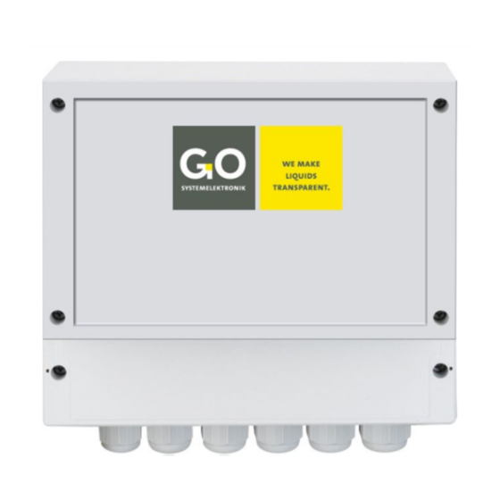
Summary of Contents for GO Systemelektronik BlueSense Module
- Page 1 Manual BlueSense Module Version of this manual: 2.3 en www.go-sys.de...
- Page 2 All rights reserved in the event of patent, utility model or design registration." Changes GO Systemelektronik GmbH retains the right to modify the contents of the manual without prior notice. Liability exclusion GO Systemelektronik GmbH takes no responsibility for correct system operation under all possible operating conditions.
-
Page 3: Table Of Contents
In the case of transnational transport routes and the associated controls, it is possible that a BlueSense Module is exposed to a too high dose of X-radiation and, as a result, stored values in the EEPROMs of the sensor plug-in cards may be affected. -
Page 4: Overview
1 Overview This user manual describes a BlueSense Module. In contrast to the BlueSense Transducer the BlueSense Module can only operate together with a BlueBox. The retrieving of the data and the configuration is done on a BlueBox or with the BlueBox PC Software. -
Page 5: Technical Data And Connection Diagrams
Ambient temperature: -10 °C to +45 °C The current outputs are optional. The type of your BlueSense Module is documented on the label on the inside of the cover lid of the cable connections. Page 5 / 16 GO Systemelektronik GmbH... -
Page 6: Connection Diagram 1 Control Parameter
B l u e S e n s e M o d u l e 2.2 Connection Diagram 1 Control Parameter The current outputs are optional. Page 6 / 16 GO Systemelektronik GmbH Faluner Weg 1 24109 Kiel Germany Tel.: +49 431 58080-0 Fax: -58080-11 www.go-sys.de... -
Page 7: Connection Diagram 2 Control Parameter
B l u e S e n s e M o d u l e 2.3 Connection Diagram 2 Control Parameter The current outputs are optional. Page 7 / 16 GO Systemelektronik GmbH Faluner Weg 1 24109 Kiel Germany Tel.: +49 431 58080-0 Fax: -58080-11 www.go-sys.de... -
Page 8: Sensor Terminal Connection Diagram
2.4 Sensor Terminal Connection Diagram If no temperature sensor is connected here, the open input must be closed with a resistor of approx. 82 kΩ. Page 8 / 16 GO Systemelektronik GmbH Faluner Weg 1 24109 Kiel Germany Tel.: +49 431 58080-0 Fax: -58080-11 www.go-sys.de... -
Page 9: Notes On The Pulse/Digital Inputs
2.6 Hazard Note Danger: Improper handling of electrical devices endangers man and property. Let carry out the commissioning of the BlueSense Module only by skilful, trained personnel using appropriate tools. Incorrect installation could cause serious faults and errors that may damage the device. -
Page 10: Commissioning
Connect the designated sensors, supply voltage and, if applicable, the relays via the crimp sockets. The crimp sockets are marked (see connection diagrams on pages 6 – 8). The cable entry is via the PG-glands. Page 10 / 16 GO Systemelektronik GmbH Faluner Weg 1 24109 Kiel Germany Tel.: +49 431 58080-0... -
Page 11: Connection To A Bluebox
B l u e S e n s e M o d u l e 4 Connection to a BlueBox Connect the cable with CAN-H and CAN-L at the BlueSense Module (see connection diagram page 6 or 7). Con- nect the BlueBox with a fitting M12-connector. -
Page 12: Procedure After Initial Start
(sensor specific) 6 Installation Notes The BlueSense Module should only be installed by skilled or instructed persons with the suitable tools. In the case of incorrect assembly serious malfunctions and errors can occur which can destroy the device. -
Page 13: Appendix A - Calibration Optical Sensors
Saves the calibration settings as .cal-file on the PC. Opens a window for choosing the file storage path. Already stored calibration settings are loaded from the PC. Opens the calibration history. Page 13 / 16 GO Systemelektronik GmbH Faluner Weg 1 24109 Kiel Germany Tel.: +49 431 58080-0 Fax: -58080-11 www.go-sys.de... -
Page 14: Recalibration
Opens the window of the calibration history. ∗ On operation with automatic range switching ( Automatic) you have to calibrate in all three areas. Page 14 / 16 GO Systemelektronik GmbH Faluner Weg 1 24109 Kiel Germany Tel.: +49 431 58080-0 Fax: -58080-11 www.go-sys.de... - Page 15 Automatic [1], before closing the window. ∗ On operation with automatic range switching ( Automatic) you have to calibrate at all three ranges. Page 15 / 16 GO Systemelektronik GmbH Faluner Weg 1 24109 Kiel Germany Tel.: +49 431 58080-0 Fax: -58080-11 www.go-sys.de...
-
Page 16: Appendix B - Eu Declaration Of Conformity
B l u e S e n s e M o d u l e Appendix B – EU Declaration of Conformity Page 16 / 16 GO Systemelektronik GmbH Faluner Weg 1 24109 Kiel Germany Tel.: +49 431 58080-0 Fax: -58080-11 www.go-sys.de...


Need help?
Do you have a question about the BlueSense Module and is the answer not in the manual?
Questions and answers