Table of Contents
Advertisement
Quick Links
Advertisement
Table of Contents

Related Manuals for GO Systemelektronik BlueBox


Summary of Contents for GO Systemelektronik BlueBox
- Page 1 Manual BlueBox DOC 486 0003-E-5.3-BDA www.go-sys.de...
- Page 2 Reproducing, copying, editing or extracting the manual contents is only allowed with the ex- press permission of GO Systemelektronik GmbH. Changes GO Systemelektronik GmbH retains the right to modify the contents of the manual without prior notice. Liability Exclusion GO Systemelektronik GmbH takes no responsibility for correct system operation under all possible operating conditions.
-
Page 3: Table Of Contents
3.3 Connecting of the power supply ..........................11 3.4 LAN-connection ............................... 12 3.5 CAN-bus termination and RS-485 termination at the BlueBox ................13 3.6 Jumper position RS-232 or RS-485 ......................... 13 4 Connection of sensor and actuator modules ........................14 4.1 Connection via M12 male plug .......................... - Page 4 Appendix C - Calibration of an oxygen sensor ........................73 Appendix D - Example configuration BlueGate-Server ..................... 74 Appendix E - Update of the BlueBox firmware ........................75 Appendix F - Opening a BlueBox housing ........................76 Appendix G - Status and error messages ......................... 77...
-
Page 5: Properties And Functions Of The Bluebox
(ISDN, analogue), EMC or Modbus (RS-232 / RS-485), current outputs (4 – 20 mA). • In mobile use it is possible to the connect the BlueBox with a GPS for the continuous position determi- nation. It is possible to connect multiple sensors/actuators to a sensor module. -
Page 6: Technical Data
To ensure equipment protection and the proper functioning of the device, the above conditions are strictly to be adhered to! ∗ The connected modules receive their power from the BlueBox. Some modules have a constricted input range, so there is a input voltage tolerance of ± 10%. Page 6 / 77... -
Page 7: Before Installation
1 x CAN connection cable with a matching cable plug 1 x 24 V DC power supply unit with a connection cable to the BlueBox (43 W or 108 W) 1 x Sensor module or actuator module with connected sensor/actuator... -
Page 8: Installation
(this is an example for a minimum delivery scope without power supply and without sensor-/actuatormodule) 1. BlueBox 2. Manual BlueBox 3. Configuration data sheet 4. Drilling template Be careful when choosing the location of the BlueBox, the location has to achieve the following properties: • rain-and sun-protected location ∗ •... -
Page 9: Connection Options
CAN-bus connection to the BlueBox sensor-/actuator modules via 4-wire CAN-Bus connection cable 4. USB connection Please note: The USB port on the BlueBox is provided for data storage and update the firmware. 5. LAN port for LAN cables in standard or cross-link design (see also 3.4). -
Page 10: Connector Pin Assignment At The Bluebox
BlueBox 3.21 Connector pin assignment at the BlueBox Power supply 24 V DC panel plug (M12, male) +24 V DC GND 24 V CAN-bus panel jack (M12, female) CAN-H CAN-L +24 V DC GND 24 V RS-232 or RS-485 panel plug (M8, male) -
Page 11: Connecting Of The Power Supply
Compare the BlueBox data for voltage and frequency with the available supply before connecting the power. Please notice that the power supply unit is placed close to the BlueBox because the voltage is declining with the length of the connecting cable. -
Page 12: Lan-Connection
Thus, a retrieval of data and direct communication with the BlueBox is possible. This requires the installation of the BlueBox PC software on your local computer (see Manual BlueBox PC Software). The connection to a network is made by a RJ-45-connector at the bottom of the BlueBox (see also 3.2 Con- nection options). -
Page 13: Can-Bus Termination And Rs-485 Termination At The Bluebox
If you need to change the jumper positions, open the housing and place the jumpers correspondingly. If the BlueBox is configured to RS-485 by GO Systemelektronik, its termination is factory preset to ON. see Appendix F - Opening a BlueBox housing... -
Page 14: Connection Of Sensor And Actuator Modules
+24 V DC brown (BN) 24 V GND BlueBox T2 and elder: If no module is connected, the BlueBox is not detected from the BlueBox PC software. Error message: Socket Error # 10061/Connection refused) ∗ The CAN-bus (Controller Area Network) is an asyn- chronous serial bus system and belongs to the field- bus. -
Page 15: Connection Via M12 Male Plug
Y-splitter Cable for data and supply 339 0001 (pass module) M 12 male plug 338 1100 M 12 Y-splitter 338 1500 Page 15 / 77 GO Systemelektronik GmbH Faluner Weg 1 24109 Kiel Germany Tel.: +49(0)431-58080-0 Fax: -58080-11 www.go-sys.de info@go-sys.de... -
Page 16: Connection Via Spring Clips
CAN-High yellow (YE) CAN-Low white (WH) +24 V DC brown (BN) 24 V GND sensor connection with spring clips (final module) Page 16 / 77 GO Systemelektronik GmbH Faluner Weg 1 24109 Kiel Germany Tel.: +49(0)431-58080-0 Fax: -58080-11 www.go-sys.de info@go-sys.de... -
Page 17: Termination Of The Can-Bus
4 24V GND leading from the M12 connector on the mother- board. Because the BlueBox is in the majority of DIP switch on position „OFF“, the termination installations at the beginning of the CAN-bus, the resistor is switched on. -
Page 18: Checking The Termination
Consider that the modules that are going to be proved are without voltage, i.e. the power supply of the BLUEBOX has to be switched off. Measure the resistance between CAN-High and CAN-Low as it is shown in the illustration. -
Page 19: Connection Of The Can-Bus Repeater
The figure below shows which connections of the CAN-bus inside the CAN repeater have to be terminated. The figure can only be seen as an example. T: Termination with DIP switch DIP switch at "ON" Page 19 / 77 GO Systemelektronik GmbH Faluner Weg 1 24109 Kiel Germany Tel.: +49(0)431-58080-0 Fax: -58080-11 www.go-sys.de... -
Page 20: The Configuration Data Sheet
BlueBox 6 The configuration data sheet The configuration data sheet contains the necessary settings to run the BlueBox. Example BlueBox TS: Page 20 / 77 GO Systemelektronik GmbH Faluner Weg 1 24109 Kiel Germany Tel.: +49(0)431-58080-0 Fax: -58080-11 www.go-sys.de info@go-sys.de... - Page 21 Is required to change the BlueBox system settings. set at the factory, not changeable Storage Device Model and size of the internal memory of the BlueBox, here CF-256 (CF = Compact Flash, 256 = 256 MB) set at the factory, changeable by replacing...
- Page 22 Password Windows xxxxx If the BlueBox is accessed via a gateway (e.g. a UMTS connection), you have to enter these access data in the BlueBox SQL Software (see Manual BlueBox PC Software, 3.2.2 Setup of a new Blue- Box).
-
Page 23: Switching On The Bluebox And Password Input
At delivery the touch panel is calibrated and ready for use. After a longer storage it may be necessary to adjust for the touch panel (see Appendix A). The setup of virtual sensors is done with the AMS software, see manual BlueBox PC Software. Page 23 / 77... - Page 24 Deletes the last entered digit. < Verifies the password and switches to the System menu. <– If the password is incorrect, you receive an error message. Page 24 / 77 GO Systemelektronik GmbH Faluner Weg 1 24109 Kiel Germany Tel.: +49(0)431-58080-0 Fax: -58080-11 www.go-sys.de...
-
Page 25: The Menu Operation
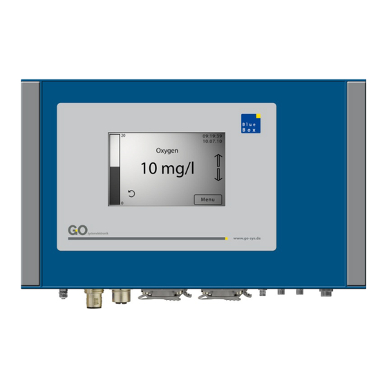
When there is no user inactivity in all other menus for 2 minutes, the software switches back to the Parame- ter display. The bar graph on the left side of the display shows the current measured value. Page 25 / 77 GO Systemelektronik GmbH Faluner Weg 1 24109 Kiel Germany Tel.: +49(0)431-58080-0 Fax: -58080-11... -
Page 26: Multiple Parameter Display
In the upper left corner you see the page number of the current display and the number of ads displayed (in this case 1/2). In the upper right corner time and date is displayed. Page 26 / 77 GO Systemelektronik GmbH Faluner Weg 1 24109 Kiel Germany Tel.: +49(0)431-58080-0 Fax: -58080-11... -
Page 27: Main Menu
Switches to the menu of the User variables. User Switches to the actuator list. Actuator list Switches to the Help menu. Help Switches to the Parameter display. <– Page 27 / 77 GO Systemelektronik GmbH Faluner Weg 1 24109 Kiel Germany Tel.: +49(0)431-58080-0 Fax: -58080-11 www.go-sys.de info@go-sys.de... -
Page 28: System Menu
Shutdown Displ ay <– Switches to the Network menu. Network Switches to the Time menu. Time Shuts down the BlueBox. Shutdown Switches to the Modem menu. Modem Switches to the GPS menu. Switches to the Display menu. Displ ay Switches to the Language menu. -
Page 29: Network Menu
System menu 8.2.1 Network The network connection allows data exchange with the BlueBox and a remote control. To ensure the accuracy of the timing, you can synchronize the time setting of the BlueBox with a timeserver. Network menu 09:19:39 10.07.10... -
Page 30: Ip-Address Menu
8.2.1.1.1 IP-Address menu Network menu 8.2.1.1 IP-Address Here you can change the IP address, which identifies the BlueBox on your local network. The IP address is configured at the factory (see 6 The configuration data sheet). The current value is displayed. -
Page 31: Netmask Menu
6 The configuration data sheet Deletes the last entered character. < Saves the netmask.. Switches back to the Network menu. <– Page 31 / 77 GO Systemelektronik GmbH Faluner Weg 1 24109 Kiel Germany Tel.: +49(0)431-58080-0 Fax: -58080-11 www.go-sys.de info@go-sys.de... -
Page 32: Gateway Ip-Address (Default Gateway)
8.2.1.1.3 Gateway IP-Address (default gateway) Network menu 8.2.1.1 Gateway If the BlueBox shall communicate via the LAN connection with other networks, enter the IP address of the device that executes the connection (another BlueBox, routers, servers, etc.). The current value is displayed. -
Page 33: Input Timeserver
Network menu 8.2.1.1 Timeser ver After entering an IP address or a Web address of a time server, the BlueBox automatically synchronizes your system time with the server time. The current IP address or web address is displayed. Saves the input and switches back to the Network menu settings. -
Page 34: Internet Settings
From this menu you can determine the manner of connection of the Blue Box to a computer on the Internet and set the connection on and off. Requires an Internet connection via the network cable to the BlueBox or an Internet connection via an inter- ∗... -
Page 35: Udp Settings
Switches to the setting of the encryption password. Password Only visible at <Enxcryption on>. Switches back to the menu Internet settings. <– Page 35 / 77 GO Systemelektronik GmbH Faluner Weg 1 24109 Kiel Germany Tel.: +49(0)431-58080-0 Fax: -58080-11 www.go-sys.de... -
Page 36: Setting Ip Address (Udp)
The UDP protocol via port 14112 is used for the transmission. The current IP address is shown. 91.221.182.141 < <– If a access to the BlueGate server was ordered, the IP address of the BlueBox is set to the default address 91.221.182.141 upon delivery. Deletes the last entered character. <... -
Page 37: Determine The Password Of The Encryption
Switches back to the Menu UDP settings without saving the input. BlueGate Settings: IP Address 91.221.182.141 xxxxx Password BlueGate see 6 The configuration settings sheet see also 8.2.1.1.5.2 Gateway settings (Internet) Page 37 / 77 GO Systemelektronik GmbH Faluner Weg 1 24109 Kiel Germany Tel.: +49(0)431-58080-0 Fax: -58080-11 www.go-sys.de info@go-sys.de... -
Page 38: Gateway Settings (Internet)
Menu Internet settings 8.2.1.1.5 Gateway settings If the BlueBox shall communicate bidirectional with a computer in the Internet, enter here the IP address of your BlueBox gateway and the associated password. IP address and password you get from GO Systemelektronik (see 6 The configuration data sheet). -
Page 39: Input Gateway Settings (Internet)
Switches between the three input menus back and forth. Deletes the last entered character. Switches back to the Menu Gateway settings (Internet) without saving the input. Page 39 / 77 GO Systemelektronik GmbH Faluner Weg 1 24109 Kiel Germany Tel.: +49(0)431-58080-0 Fax: -58080-11 www.go-sys.de... -
Page 40: Dyndns Settings
09:19:39 10.07.10 Host Username Password <– Input Name under which the BlueBox on DynDNS can be reached Host Input Login Username of your DynDNS account Username Input Login password of your DynDNS account Password Switches back to the menu Internet settings. -
Page 41: Input Dyndns Settings
Switches between the three input menu back and forth. Deletes the last entered character. Switches back to the Menu DynDNS without saving the input. Page 41 / 77 GO Systemelektronik GmbH Faluner Weg 1 24109 Kiel Germany Tel.: +49(0)431-58080-0 Fax: -58080-11 www.go-sys.de... -
Page 42: Info Network
Switches to the input of the time zone. Time zone Switches to the input of the time drift. Time drift Switches back to the System menu. <– Page 42 / 77 GO Systemelektronik GmbH Faluner Weg 1 24109 Kiel Germany Tel.: +49(0)431-58080-0 Fax: -58080-11 www.go-sys.de info@go-sys.de... -
Page 43: Date Menu
Selection of month setting Month Selection of year setting Year selection -1 selection +1 Switches back to the Time menu. <– Page 43 / 77 GO Systemelektronik GmbH Faluner Weg 1 24109 Kiel Germany Tel.: +49(0)431-58080-0 Fax: -58080-11 www.go-sys.de info@go-sys.de... -
Page 44: Time Menu
<– First set the time zone before you set the time. Summer time is adjusted only by changing the time zone (e.g. from +1 to +2). Page 44 / 77 GO Systemelektronik GmbH Faluner Weg 1 24109 Kiel Germany Tel.: +49(0)431-58080-0 Fax: -58080-11 www.go-sys.de... -
Page 45: Time Zone Menu
< Saves the input and switches back to the Time menu. Switches back to the Time menu without saving the input. <– Page 45 / 77 GO Systemelektronik GmbH Faluner Weg 1 24109 Kiel Germany Tel.: +49(0)431-58080-0 Fax: -58080-11 www.go-sys.de... -
Page 46: Shutdown
BlueBox 8.2.1.3 Shutdown System menu 8.2.1 Shutdown For a proper operation it is necessary to shut down the BlueBox before disconnecting the power supply. Shutdown? 09:19:39 10.07.10 Shutdown of the BlueBox Switches back to the System menu The state of the shutdown is displayed. -
Page 47: Modem Menu / Modem Settings
(see: 8.2.1.4.3 Modem type settings ). Switches to the Info menu of the modem settings. Info Switches back to the System menu. <– Page 47 / 77 GO Systemelektronik GmbH Faluner Weg 1 24109 Kiel Germany Tel.: +49(0)431-58080-0 Fax: -58080-11 www.go-sys.de... -
Page 48: Modem Port Setup
USB 1 For special cases, e.g. if USB 1 is allocated to a GPS receiver. Switches back to the Modem Menu. <– Page 48 / 77 GO Systemelektronik GmbH Faluner Weg 1 24109 Kiel Germany Tel.: +49(0)431-58080-0 Fax: -58080-11 www.go-sys.de... -
Page 49: Input Of The Pin Number
< Saves the input and switches back to the Modem Menu. Switches back to the Modem Menu without saving the input. <– Page 49 / 77 GO Systemelektronik GmbH Faluner Weg 1 24109 Kiel Germany Tel.: +49(0)431-58080-0 Fax: -58080-11 www.go-sys.de... -
Page 50: Modem Type Settings
A GPRS modem* or a UMTS modem is connected. GPRS/UM TS GPRS/UM TS Saves the input and switches back to the Modem Menu. <– ∗ optional extra equipment Page 50 / 77 GO Systemelektronik GmbH Faluner Weg 1 24109 Kiel Germany Tel.: +49(0)431-58080-0 Fax: -58080-11 www.go-sys.de info@go-sys.de... -
Page 51: Umts Settings
Switches back to the Modem Menu. <– The routing must be switched on, if you use this BlueBox as an Internet router. This is for example the case, when via this BlueBox other BlueBoxes send measured values. Please note that the connected BlueBoxes must use the IP address of the routing BlueBox as the address of the default gateway see (8.2.1.1.3). -
Page 52: Input Umts Settings
Display of the actual settings of the UMTS modem RX bytes: received data since connection started TX bytes: transfered data since connection started Page 52 / 77 GO Systemelektronik GmbH Faluner Weg 1 24109 Kiel Germany Tel.: +49(0)431-58080-0 Fax: -58080-11 www.go-sys.de... -
Page 53: Gps Menu
USB interface is activated for the GPS receiver by the USB 2 manufacturer via this button. Switches back to the GPS menu. <– Page 53 / 77 GO Systemelektronik GmbH Faluner Weg 1 24109 Kiel Germany Tel.: +49(0)431-58080-0 Fax: -58080-11 www.go-sys.de... -
Page 54: Display
• The parameters of all sensors and the status of all actuators are displayed. • The parameters of all sensors are displayed. Switches back to the system menu. <– Page 54 / 77 GO Systemelektronik GmbH Faluner Weg 1 24109 Kiel Germany Tel.: +49(0)431-58080-0 Fax: -58080-11 www.go-sys.de... -
Page 55: Language Settings
Selection menu language Spanish, the button is also a status indicator. Español Selection menu language French, the button is also a status indicator. Française Switches back to the system menu. <– Page 55 / 77 GO Systemelektronik GmbH Faluner Weg 1 24109 Kiel Germany Tel.: +49(0)431-58080-0 Fax: -58080-11 www.go-sys.de info@go-sys.de... -
Page 56: Sensor List
Switches to the menu of the temperature sensor. Temperature Scrolls the list. Switches back to the Main menu. <– Page 56 / 77 GO Systemelektronik GmbH Faluner Weg 1 24109 Kiel Germany Tel.: +49(0)431-58080-0 Fax: -58080-11 www.go-sys.de info@go-sys.de... -
Page 57: Sensor Menu
Cal. mode Only visible with sensors, in which a selection of calibration mode is possible. Switches back to the sensor menu. <– Page 57 / 77 GO Systemelektronik GmbH Faluner Weg 1 24109 Kiel Germany Tel.: +49(0)431-58080-0 Fax: -58080-11 www.go-sys.de... -
Page 58: Interval And Average
< Saves the input and switches back to the Sensor menu. Switches back to the Sensor menu without saving the input. <– Page 58 / 77 GO Systemelektronik GmbH Faluner Weg 1 24109 Kiel Germany Tel.: +49(0)431-58080-0 Fax: -58080-11 www.go-sys.de... -
Page 59: Calibration
BlueBox 8.2.3.2 Calibration Sensor menu 8.2.3 Calib ration The BlueBox allows calibration of sensors in the connected state. Calibration is password protected, see: 7 Switching on the BlueBox and password input. Oxygen 09:19:39 10.07.10 O x y g e n c a l i b r a t i o n 0.0 mg/l... -
Page 60: Table Display (Sensor Values)
Displays the measurement values of the previous day. < Displays the measurement values of the nest day. > Switches to the sensor menu. <– Page 60 / 77 GO Systemelektronik GmbH Faluner Weg 1 24109 Kiel Germany Tel.: +49(0)431-58080-0 Fax: -58080-11 www.go-sys.de info@go-sys.de... -
Page 61: Diagram Display (Sensor Values)
Measurement values over the past 21 - 24 hours (depending on the range of values). Pushing on the display switches to the sensor menu. Page 61 / 77 GO Systemelektronik GmbH Faluner Weg 1 24109 Kiel Germany Tel.: +49(0)431-58080-0 Fax: -58080-11 www.go-sys.de... -
Page 62: Sensor Info
Unit unit of the parameter Last update date of the last measurement Switches back to the sensor menu. <– Page 62 / 77 GO Systemelektronik GmbH Faluner Weg 1 24109 Kiel Germany Tel.: +49(0)431-58080-0 Fax: -58080-11 www.go-sys.de info@go-sys.de... -
Page 63: Selection Calibration Mode
BlueBox 8.2.3.6 Selection calibration mode Sensor menu 8.2.3 Cal. mode Here you can set the calibration mode of a sensor. GO Systemelektronik recommends using the default setting. One point calib ration y0=0 One point calib ration y0=fix Two point calib ration <–... -
Page 64: User Variables
Example with two user variables Variable1 Variable2 <– The AMS program as part of the BlueBox PC Software allows users to define variables that can be changed directly in the BlueBox. Switches to the menu of the first variable. Variable1 Switches to the menu of the second variable. -
Page 65: Actuator List
Relay 1 Switches to the menu of the second actuator. Relay 2 Scrolls the list. Switches back to the Main menu. Page 65 / 77 GO Systemelektronik GmbH Faluner Weg 1 24109 Kiel Germany Tel.: +49(0)431-58080-0 Fax: -58080-11 www.go-sys.de info@go-sys.de... -
Page 66: Actuator Menu
Selects the actuator for the multiple parameter display or not. Selected see also 8.2.1.6 Display Selected Switches back to the main menu. <– Page 66 / 77 GO Systemelektronik GmbH Faluner Weg 1 24109 Kiel Germany Tel.: +49(0)431-58080-0 Fax: -58080-11 www.go-sys.de info@go-sys.de... -
Page 67: Actuator Setting
Switches the relay on, the button is also a status indicator. Switches the relay off, the button is also a status indicator. Switches back to the Actuator menu. <– Page 67 / 77 GO Systemelektronik GmbH Faluner Weg 1 24109 Kiel Germany Tel.: +49(0)431-58080-0 Fax: -58080-11 www.go-sys.de... -
Page 68: Diagram Display (Actuator)
The update function is used for a function query and happens after each inspection interval. Switches back to the Actuator menu. <– Page 68 / 77 GO Systemelektronik GmbH Faluner Weg 1 24109 Kiel Germany Tel.: +49(0)431-58080-0 Fax: -58080-11 www.go-sys.de... -
Page 69: Help Menu
Vir tual Sensors = 1 / 1 Software Version = 2.69.82 = N/V <– Switches back to the Help menu. <– Page 69 / 77 GO Systemelektronik GmbH Faluner Weg 1 24109 Kiel Germany Tel.: +49(0)431-58080-0 Fax: -58080-11 www.go-sys.de info@go-sys.de... -
Page 70: Plug And Clip Connection
BlueBox 8.2.6.2 Plug and clip connection Help menu 8.2.6 Shows the pin assignments at the BlueBox for the current version. M12 Plug 4 p l u g m a l e [ 3 3 8 1 1 0 0 ]... -
Page 71: Appendix A - Adjustment Of The Touch Display
Press the blinking dot top left. A blinking dot appears at bottom right. Press the blinking dot bottom right. The adjustment is finished. Page 71 / 77 GO Systemelektronik GmbH Faluner Weg 1 24109 Kiel Germany Tel.: +49(0)431-58080-0 Fax: -58080-11 www.go-sys.de... -
Page 72: Appendix B - Calibrating A Ph Sensor
For the two-point calibration you need two calibration fluids with different pH values, eg pH 4 and pH 9.2. In this two-point calibration it is always the lower value first and then the higher value is measured. The Bluebox independently calculates the calibration curve. The calibration fluids are available as accessories under the item no. 3615910 at GO-Systemelektronik. -
Page 73: Appendix C - Calibration Of An Oxygen Sensor
Calibration in air Hold the oxygen sensor approximately 15 minutes to the air. Enter -1 The calibration is completed. Continue with After 2 seconds the BlueBox Continue with switches to the measurand repre- sentation. Page 73 / 77 GO Systemelektronik GmbH... -
Page 74: Appendix D - Example Configuration Bluegate-Server
If a time server is connected to the BlueBox the following configuration is necessary: • Port 37 TCP/UDP <-> Timeserver IP. Note: If the internal network is not a Class A, B or C network then communication with the BlueBox is only possible over: •... -
Page 75: Appendix E - Update Of The Bluebox Firmware
BlueBox Appendix E - Update of the BlueBox firmware Precondition is an operating LAN connection of the BlueBox. Start FirmwareUpdate.exe on your PC. Firmware version of the update Click <Update> • Select the tab <Default>. • Enter the network password of the BlueBox. -
Page 76: Appendix F - Opening A Bluebox Housing
Shut down the BlueBox. Disconnect the BlueBox from the power supply. 1. Remove the covers on both sides of the BlueBox. 2. Unscrew the four fixing screws. 3. Open the housing by hinging the cover from the front to the back. -
Page 77: Appendix G - Status And Error Messages
Description The sensor sends data. Parameter No data The sensor sends no data. Wait The BlueBox is waiting for the first measured value. Sensor warning, the measured value may be faulty. Parameter Calc error AMS formula error ? Sensor In an AMS formula an unknown sensor is used.
Need help?
Do you have a question about the BlueBox and is the answer not in the manual?
Questions and answers