Table of Contents
Advertisement
Quick Links
Advertisement
Table of Contents

Related Manuals for GO Systemelektronik BlueSense


Summary of Contents for GO Systemelektronik BlueSense
- Page 1 Manual BlueSense Transducer Version of the manual: 3.1 en www.go-sys.de...
- Page 2 Reproducing, copying, editing or extracting the manual contents is only allowed with the ex- press permission of GO Systemelektronik GmbH. Changes GO Systemelektronik GmbH retains the right to modify the contents of the manual without prior notice. Liability Exclusion GO Systemelektronik GmbH takes no responsibility for correct system operation under all possible operating conditions.
- Page 3 BlueSense blank page Page 3 / 55 GO Systemelektronik GmbH Faluner Weg 1 24109 Kiel Germany Tel.: +49 431 58080-0 Fax: -58080-11 www.go-sys.de info@go-sys.de...
-
Page 4: Table Of Contents
8 Programs ..................................35 8.1 Flushcontrol Parameters ............................37 8.2 Parameter PID ............................... 38 8.2.1 Parameter PID (Sensor selection) ........................40 Page 4 / 55 GO Systemelektronik GmbH Faluner Weg 1 24109 Kiel Germany Tel.: +49 431 58080-0 Fax: -58080-11 www.go-sys.de... - Page 5 Appendix G - Differentiation motherboard Version AB ..................... 50 Appendix H - Multipoint calibration ..........................51 Appendix I - Menu structure ............................53 Page 5 / 55 GO Systemelektronik GmbH Faluner Weg 1 24109 Kiel Germany Tel.: +49 431 58080-0 Fax: -58080-11 www.go-sys.de...
-
Page 6: Overview
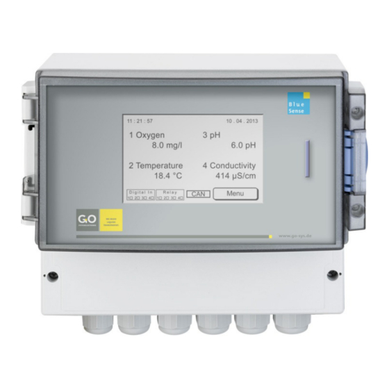
BlueSense 1 Overview This user manual describes a BlueSense-Transducer. The Transducer • receives the signals of the connected sensors, • generates there from measurement values, • displays the measurement values, • transduces the measurement values into analogue current values (4 – 20 mA), •... - Page 7 Basic structure of the menu navigation: Parameter Display Main Menu Sensors Setup Comport Memory Card Programs see Appendix I - Menu structure Page 7 / 55 GO Systemelektronik GmbH Faluner Weg 1 24109 Kiel Germany Tel.: +49 431 58080-0 Fax: -58080-11 www.go-sys.de info@go-sys.de...
-
Page 8: Technical Data And Connection Diagrams
Weight: 1.35 kg ∗ The equipment of your transducer is documented on the sticker on the inside of the cover for the cable connections. Page 8 / 55 GO Systemelektronik GmbH Faluner Weg 1 24109 Kiel Germany Tel.: +49 431 58080-0 Fax: -58080-11 www.go-sys.de... -
Page 9: Connection Diagram 1 Control Parameter
BlueSense 2.2 Connection diagram 1 control parameter Page 9 / 55 GO Systemelektronik GmbH Faluner Weg 1 24109 Kiel Germany Tel.: +49 431 58080-0 Fax: -58080-11 www.go-sys.de info@go-sys.de... -
Page 10: Sensor Terminal Connection Diagram
BlueSense 2.3 Connection diagram 2 control parameter Page 10 / 55 GO Systemelektronik GmbH Faluner Weg 1 24109 Kiel Germany Tel.: +49 431 58080-0 Fax: -58080-11 www.go-sys.de info@go-sys.de... - Page 11 On motherboard Version A the shield cable is connected with PIN 3 of slot X10. If no temperature sensor is con- nected, the open input must be closed with a resistor of 82 kΩ. Page 11 / 55 GO Systemelektronik GmbH Faluner Weg 1 24109 Kiel Germany Tel.: +49 431 58080-0 Fax: -58080-11 www.go-sys.de...
-
Page 12: Commissioning
The touch-panel is balanced and ready for use. A long storage by the customer may cause the neces- sary of a new adjustment (see Appendix C - Adjustment of the touch display). Page 12 / 55 GO Systemelektronik GmbH Faluner Weg 1 24109 Kiel Germany Tel.: +49 431 58080-0... -
Page 13: Turning On The System
When there is user inactivity in all other menus, the software switches in 2 minutes back to the Parameter Display. Not valid for input menus. Switch to the Main Menu Menu Page 13 / 55 GO Systemelektronik GmbH Faluner Weg 1 24109 Kiel Germany Tel.: +49 431 58080-0 Fax: -58080-11 www.go-sys.de... -
Page 14: Main Menu
Switch to the Programme menu, § 8. Switch to the display of the firmware version, § 9. Switch back to the Parameter Display. Switch to the Parameter Display. Page 14 / 55 GO Systemelektronik GmbH Faluner Weg 1 24109 Kiel Germany Tel.: +49 431 58080-0 Fax: -58080-11 www.go-sys.de... -
Page 15: Setup
Switch to language setting menu, § 5.4 Switch to the time and date entry menu, § 5.5 Switch back to the Main Menu. Switch to the Parameter Display. Page 15 / 55 GO Systemelektronik GmbH Faluner Weg 1 24109 Kiel Germany Tel.: +49 431 58080-0 Fax: -58080-11 www.go-sys.de... -
Page 16: Sensors
Switch to the information about the state of the digital inputs, § 6.1.3. Switch back to the Setup menu. Switch to the Parameter Display. Page 16 / 55 GO Systemelektronik GmbH Faluner Weg 1 24109 Kiel Germany Tel.: +49 431 58080-0 Fax: -58080-11 www.go-sys.de... -
Page 17: Oxygen Sensor Setup (Control Parameter)
§ 5.1.1.5 Switch back to the Sensors menu. Switch to the Parameter Display. Page 17 / 55 GO Systemelektronik GmbH Faluner Weg 1 24109 Kiel Germany Tel.: +49 431 58080-0 Fax: -58080-11 www.go-sys.de... -
Page 18: Calibration
Saves the calibration and switches to Sensor setup. The calibration is saved and completed. ∗ Exceptions possible, see Appendix H - Multipoint calibration Page 18 / 55 GO Systemelektronik GmbH Faluner Weg 1 24109 Kiel Germany Tel.: +49 431 58080-0 Fax: -58080-11 www.go-sys.de... -
Page 19: Example 2-Point-Calibration Orp
With the List menu you can check the calibration values. Aborts the calibration and switches to Sensor setup. Saves the calibration and switches to Sensor setup. The calibration is saved and completed. Page 19 / 55 GO Systemelektronik GmbH Faluner Weg 1 24109 Kiel Germany Tel.: +49 431 58080-0 Fax: -58080-11 www.go-sys.de... -
Page 20: Relay
(RSP). The Switchback-Hysteresis value (RHY) determines the Switchbackpoint (Switchpoint mi-nus Switchback-Hysteresis = Switchbackpoint). maximum switching value (Max.) is SP RSP is SP minus the switchback hysteresis value Page 20 / 55 GO Systemelektronik GmbH Faluner Weg 1 24109 Kiel Germany Tel.: +49 431 58080-0 Fax: -58080-11 www.go-sys.de... -
Page 21: Current Output
Saves the input and switches to the next menu. Without setting the old value is stored. The current settings are saved and completed. Page 21 / 55 GO Systemelektronik GmbH Faluner Weg 1 24109 Kiel Germany Tel.: +49 431 58080-0 Fax: -58080-11 www.go-sys.de... -
Page 22: Change Name
BlueBox. Switches to the setting of the measurement interval. Switch back to Sensor control-parameter setup. Switch to the Parameter Display. Page 22 / 55 GO Systemelektronik GmbH Faluner Weg 1 24109 Kiel Germany Tel.: +49 431 58080-0 Fax: -58080-11 www.go-sys.de... -
Page 23: Minimum Value And Maximum Value
Aborts the input and switches to the Parameter menu. Deletes the last entered character. Saves the input and switches back to the Parameter menu. Without setting the old value is stored. Page 23 / 55 GO Systemelektronik GmbH Faluner Weg 1 24109 Kiel Germany Tel.: +49 431 58080-0 Fax: -58080-11 www.go-sys.de... -
Page 24: Average And Interval
Switches back to the Parameter menu without saving the input. Deletes the last entered character. Saves the input and switch back to the Parameter menu. Without setting the old value is stored. Page 24 / 55 GO Systemelektronik GmbH Faluner Weg 1 24109 Kiel Germany Tel.: +49 431 58080-0 Fax: -58080-11 www.go-sys.de... -
Page 25: Temperature Sensor Setup (Associated Parameter)
Setup menu Here the state of the digital inputs is displayed. If no sensor is connected, either 0 or 0.0 is displayed. Switch back to the Setup menu Page 25 / 55 GO Systemelektronik GmbH Faluner Weg 1 24109 Kiel Germany Tel.: +49 431 58080-0... -
Page 26: Reset
Exception: Sensor calibration data remains unchanged. Switch back to the display of Measured Values. Switch back to the Setup menu. Switch to the Parameter Display. Page 26 / 55 GO Systemelektronik GmbH Faluner Weg 1 24109 Kiel Germany Tel.: +49 431 58080-0 Fax: -58080-11 www.go-sys.de... -
Page 27: Comport
The button is also a status indicator. Only visible if a CAN-bus interface is existing. Switch back to the Setup menu. Switch to the Parameter Display. Page 27 / 55 GO Systemelektronik GmbH Faluner Weg 1 24109 Kiel Germany Tel.: +49 431 58080-0 Fax: -58080-11 www.go-sys.de... -
Page 28: Protocol Selection
Switch back to the Comport menu without saving the input. Deletes the last entered character. Save the input and switch back to the Comport menu. Without setting the old value is stored. Page 28 / 55 GO Systemelektronik GmbH Faluner Weg 1 24109 Kiel Germany Tel.: +49 431 58080-0 Fax: -58080-11 www.go-sys.de... -
Page 29: Language Setting
PYCCKИЙ The button is also a status indicator. Switch back to the Setup menu. Switch to the display of Measured Values. Page 29 / 55 GO Systemelektronik GmbH Faluner Weg 1 24109 Kiel Germany Tel.: +49 431 58080-0 Fax: -58080-11 www.go-sys.de... -
Page 30: Time / Date
Increases the year / month / date by 1 Switch back to the Setup menu without storing the entry. Save the entry and switch back to the Setup menu. Page 30 / 55 GO Systemelektronik GmbH Faluner Weg 1 24109 Kiel Germany Tel.: +49 431 58080-0... -
Page 31: Screen
If the backlight is off, it can be turned on again by pressing any button. The button is also a status indicator. Switch back to the Main Menu. Switch to the display of Measured Values. Page 31 / 55 GO Systemelektronik GmbH Faluner Weg 1 24109 Kiel Germany Tel.: +49 431 58080-0 Fax: -58080-11 www.go-sys.de... -
Page 32: Memory Card
Switch to the input of the storage interval. Switch to the firmware update. Switch back to the Main Menu. Switch to the Parameter Display. Page 32 / 55 GO Systemelektronik GmbH Faluner Weg 1 24109 Kiel Germany Tel.: +49 431 58080-0 Fax: -58080-11 www.go-sys.de... -
Page 33: Adjustment Of The Storage Interval
Main Menu Starts the Firmware-Update. Follow the instructions. Switch back to the Main Menu. Switch to the display of Measured Values. Page 33 / 55 GO Systemelektronik GmbH Faluner Weg 1 24109 Kiel Germany Tel.: +49 431 58080-0 Fax: -58080-11 www.go-sys.de... -
Page 34: Read Data
Example: opening a csv-file with the program Calc from the OpenOffice package. Note: If you selected English as the menu language of the BlueSense-Transducer, the decimal separator is a dot. -
Page 35: Programs
Pressing the activated button switches to the PID control parameters (see § 8.2). ∗ Is only effective if the PID controller is activated in the parameterization (see § 8.2). Page 35 / 55 GO Systemelektronik GmbH Faluner Weg 1 24109 Kiel Germany Tel.: +49 431 58080-0 Fax: -58080-11 www.go-sys.de... - Page 36 BlueSense Switch to the Main Menu. Switch to the Parameter Display. Switch to another programs menu, here without content. Page 36 / 55 GO Systemelektronik GmbH Faluner Weg 1 24109 Kiel Germany Tel.: +49 431 58080-0 Fax: -58080-11 www.go-sys.de info@go-sys.de...
-
Page 37: Flushcontrol Parameters
Saves the input and switches to the next menu. Without setting the old value is stored. The settings of the Flushcontrol are saved and completed. Page 37 / 55 GO Systemelektronik GmbH Faluner Weg 1 24109 Kiel Germany Tel.: +49 431 58080-0 Fax: -58080-11 www.go-sys.de... -
Page 38: Parameter Pid
Deletes the last entered character. Saves the input and switches to the next menu. Without setting the old value is stored. Page 38 / 55 GO Systemelektronik GmbH Faluner Weg 1 24109 Kiel Germany Tel.: +49 431 58080-0 Fax: -58080-11 www.go-sys.de... - Page 39 Switch back to the Programs Menu. Switch to the Parameter Display. ∗ e.g. for a sensor calibration Page 39 / 55 GO Systemelektronik GmbH Faluner Weg 1 24109 Kiel Germany Tel.: +49 431 58080-0 Fax: -58080-11 www.go-sys.de...
-
Page 40: Parameter Pid (Sensor Selection)
The serial number of the transducer is also the CAN-ID (in other contexts also called DAM-ID) of the transducer for a connected BlueBox (bls + 5 digits). Page 40 / 55 GO Systemelektronik GmbH Faluner Weg 1 24109 Kiel Germany Tel.: +49 431 58080-0... -
Page 41: Version Notice
12 Maintenance instructions The Transducer itself is maintenance free. The sensors, however, should be periodically cleaned and cali- brated. The timeframes for cleaning and calibration depend heavily on the application. GO Systemelektronik GmbH Page 41 / 55 GO Systemelektronik GmbH... -
Page 42: Appendix A - Modbus
BlueSense - Modbus Appendix A - Modbus 1. Introduction The functionality of the Modbus protocol is limited to the following switches and registers. In future versions all settings will be able to be controlled via Modbus. The registers are 32 bit. - Page 43 BlueSense - Modbus 2.3 Analogue Output Holding Registers (Read & Write) Number Address Description Data format Size 0x0000 analogue value of current output 1 Double 1 Register 0x0001 analogue value of current output 2 Double 1 Register 0x0002 reserved for future functions...
- Page 44 BlueSense - Modbus 2.4 Analogue Input Register (Read Only) Number Address Description Data format Size 0x0000 first measurement value Double 1 Register 0x0001 second measurement value Double 1 Register 0x0002 third measurement value Double 1 Register 0x0003 fourth measurement value...
-
Page 45: Appendix B - Connection To A Bluebox
BlueSense - Connection BlueBox Appendix B - Connection to a BlueBox Precondition: The transducer has a CAN-bus interface. Connect the cable with CAN-H and CAN-L at the transducer (see connection diagram page 9 or 10). Connect the BlueBox with a fitting M12-connector. -
Page 46: Appendix C - Adjustment Of The Touch Display
BlueSense - Adjustment touch display Appendix C - Adjustment of the touch display If the display responses not, wrong or only under large pressure, a display adjustment is necessary. While switching on power, press display until the notice "touch adjustment ? don't touch for normal use"... -
Page 47: Appendix D - Housing Dimensions
BlueSense - Housing dimensions Appendix D - Housing dimensions Page 47 / 55 GO Systemelektronik GmbH Faluner Weg 1 24109 Kiel Germany Tel.: +49 431 58080-0 Fax: -58080-11 www.go-sys.de info@go-sys.de... -
Page 48: Appendix E - Status And Error Messages
BlueSense - Status and error messages Appendix E - Status and error messages 1 Status messages 11 : 21 : 57 10 . 04 . 2013 1 Oxygen 4 Temperature 2 8.0 mg/l 19.0 °C 2 Temperature 1 5 Salinity 18.4 °C... - Page 49 BlueSense - Status and error messages 2 Error messages Description of the error Error number Error messages appear in a separate menu. The backlight of the display flashes. Switch back to the previous menu. Password error • incorrect password input...
-
Page 50: Appendix F - Dip Switch Configuration
If these jumper slots exist, it is motherboard Version B. If these jumper slots do not exist, it is motherboard Version A. If the motherboard can not be clearly assigned, please contact GO Systemelektronik. Page 50 / 55 GO Systemelektronik GmbH... -
Page 51: Appendix H - Multipoint Calibration
BlueSense - Multipoint calibration Appendix H - Multipoint calibration Multipoint calibration, example turbidity 1. Request Activation of the calibration menu ∗ 2. Input of the measurement points Here you enter the number of measurement points. Switch back to the turbidity menu without saving the input. - Page 52 BlueSense - Multipoint calibration 3. Input of the calibration values Immerse the sensor into the calibration medium. Enter the turbidity value of the calibration medium. actual number of the measurement point / number of measurement points actual measurement value and therefore reference value, here 0.0 unit of the measurement, here FNU for turbidity Aborts the calibration and switches back to the turbidity menu.
-
Page 53: Appendix I - Menu Structure
BlueSense - Menu structure Appendix I - Menu structure Main structure see § 4.1.1 Parameter Display see § 4.1.2 Main menu see § 5 Setup see § 5.1 Sensors see § 5.2 Reset see § 5.3 Comport see § 5.4 Language see §... - Page 54 BlueSense - Menu structure Sensors see § 5.1 Sensors see § 5.1.1 Sensor X see § 5.1.1.1 Calibration see § 5.1.1.2 Relay see § 5.1.1.3 Current Output see § 5.1.1.4 Change Name see § 5.1.1.5 Parameter see § 5.1.1.5.1 Minimum value Maximum value see §...
- Page 55 BlueSense - Menu structure Memory Card Memory Card see § 7 Start/Stop see § 7.2 Interval see § 7.3 Update Programs Programs Regulation intern see § 8 Regulation extern Compensation Flushcontrol see § 8 Flushtime see § 8.1 see § 8.1...
Need help?
Do you have a question about the BlueSense and is the answer not in the manual?
Questions and answers