Table of Contents
Advertisement
Quick Links
Customer:
Job Number:
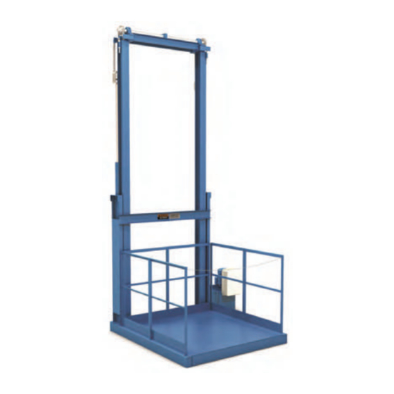
21 Series | Hydraulic VRC
2-Post Cantilever
Installation Manual
Important:
Read this entire manual.
Important safety information
is included.
Before starting the installation,
verify the job site dimensions and the
dimensions of the delivered materials
against the PFlow Industries, Inc.
General Arrangement (GA) drawing.
The illustrations depicted in this manual
are not to scale or detail. The illustrations
are for reference only.
15707-2001 | Rev - | 2018-07-01 | Printed in the U.S.A.
www.pflow.com
P 414 352 9000
F 414 352 9002
6720 N. Teutonia Ave.
Milwaukee, WI 53209
Advertisement
Table of Contents

Related Manuals for PFlow Industries 21 Series


Summary of Contents for PFlow Industries 21 Series
- Page 1 P 414 352 9000 F 414 352 9002 6720 N. Teutonia Ave. Milwaukee, WI 53209 Customer: Job Number: 21 Series | Hydraulic VRC 2-Post Cantilever Installation Manual Important: Read this entire manual. Important safety information is included. Before starting the installation,...
- Page 2 www.pflow.com P 414 352 9000 Table of Contents F 414 352 9002 6720 N. Teutonia Ave. Milwaukee, WI 53209 Description Section | Page 1. Contact Information 15705-0011 1 | 1 2. General Information 15710-0004 2 | 1 Introduction 2 | 1 General Overview 2 | 1 Code Requirements...
- Page 3 www.pflow.com P 414 352 9000 Table of Contents F 414 352 9002 6720 N. Teutonia Ave. Milwaukee, WI 53209 Description Section | Page 6. Equipment Arrival and Unpacking 15710-0006 6 | 1 Arrival 6 | 1 Inspection 6 | 1 Transportation Damage and Claims 6 | 1 Shipping Photograph Examples...
- Page 4 www.pflow.com P 414 352 9000 Table of Contents F 414 352 9002 6720 N. Teutonia Ave. Milwaukee, WI 53209 Description Section | Page 12. Column Setup (continued) Align the Wheelblocks to the Guide Angle 12 | 10 Review the Columns for Plumb 12 | 10 Install the Header Assembly 12 | 11...
- Page 5 www.pflow.com P 414 352 9000 Table of Contents F 414 352 9002 6720 N. Teutonia Ave. Milwaukee, WI 53209 Description Section | Page 16. Gate Installation 15709-0005 16 | 1 Identify Components 16 | 1 Sliding Gate 16 | 2 Assemble the Sliding Gate 16 | 2 Install the Gate Post Extensions...
- Page 6 www.pflow.com P 414 352 9000 Table of Contents F 414 352 9002 6720 N. Teutonia Ave. Milwaukee, WI 53209 Description Section | Page 16. Gate Installation (continued) Single Vertical Acting (SVA) Gate 16 | 14 Establish Placement 16 | 14 Prepare the Chains in the Gate Posts 16 | 15 Begin Horizontal Assembly...
- Page 7 www.pflow.com P 414 352 9000 Table of Contents F 414 352 9002 6720 N. Teutonia Ave. Milwaukee, WI 53209 Description Section | Page 16. Gate Installation (continued) Carriage Mounted Single Vertical Acting (SVA) Gate 16 | 29 Establish Placement 16 | 29 Prepare the Chains in the Gate Posts 16 | 30 Begin Horizontal Assembly...
- Page 8 www.pflow.com P 414 352 9000 Table of Contents F 414 352 9002 6720 N. Teutonia Ave. Milwaukee, WI 53209 Description Section | Page 17. Gate Cable Interlock 15709-0029 17 | 1 Purpose 17 | 1 General Description 17 | 3 Carriage Cam 17 | 3 Column Mounted Roller Assembly...
- Page 9 www.pflow.com P 414 352 9000 Table of Contents F 414 352 9002 6720 N. Teutonia Ave. Milwaukee, WI 53209 Description Section | Page 21. Hydraulic Installation and Start-up Procedures (continued) Route the Hydraulic Hoses 21 | 5 Attach the Fitting and Hose to the 21 | 5 Hydraulic Pump Attach the Upper High Pressure Hoses to the...
-
Page 10: Options Description
www.pflow.com P 414 352 9000 Table of Contents F 414 352 9002 6720 N. Teutonia Ave. Milwaukee, WI 53209 Customer Information Customer Name Job Number Options Description Document # Revision Safety Data Sheets Description Document # Revision Bill of Material Sheets Document # TOC | 10... - Page 11 www.pflow.com P 414 352 9000 Table of Contents F 414 352 9002 6720 N. Teutonia Ave. Milwaukee, WI 53209 Customer Information Customer Name Job Number Job Drawings Description Document # Revision...
- Page 12 www.pflow.com P 414 352 9000 Table of Contents F 414 352 9002 6720 N. Teutonia Ave. Milwaukee, WI 53209 TOC | 12...
-
Page 13: Contact Information
Product Support Department e-mail: psd@p ow.com Sales e-mail: sales@p ow.com For a list of contact personnel visit the PFlow Industries, Inc. website at: http://www.p ow.com/contact-us/ Documentation PFlow Industries, Inc. reserves the right to make changes or improvements to the standard model line at any time. PFlow Industries, Inc. reserves the right to make changes to subsequent editions of the manual without prior notice to holders of this edition. - Page 14 www.pflow.com P 414 352 9000 Contact Information Section 1 | F 414 352 9002 6720 N. Teutonia Ave. Milwaukee, WI 53209...
-
Page 15: Section 2 | General Information
VRCs general installation. The information and illustrations do not cover every possible contingency or circumstance regarding nonstandard options or site conditions. If there is a problem, call PFlow Industries, Inc. at (414) 352-9000, during normal business hours, 8:30 a.m. to 5:00 p.m. central standard time, Monday through Friday. - Page 16 www.pflow.com P 414 352 9000 General Information Section 2 | F 414 352 9002 6720 N. Teutonia Ave. Milwaukee, WI 53209...
-
Page 17: Warranty Information
7. Lost time and/or additional trips for missing or damaged components. 8. Expedited freight charges. The obligation for PFlow Industries, Inc. is limited to only the replacement or repair of defective components that received prior authorization. This is the owner’s sole remedy. - Page 18 Notify PFlow Industries, Inc. by phone, FAX, or e-mail during the next business day if an event NOTE occurs during our non-working hours. Issuance of an authorization number does not guarantee approval and/or payment.
-
Page 19: Section 4 | Important Safety
Instructions and warnings must be read and thoroughly understood by all operators and users. PFlow Industries, Inc. recommends that the owner conduct regular sta training including safety instructions on a regular basis to avoid the risk of accident or damage to the VRC. - Page 20 www.pflow.com P 414 352 9000 Important Safety Section 4 | F 414 352 9002 6720 N. Teutonia Ave. Information Milwaukee, WI 53209 Stay within the rated li capacity. Make sure all safety devices are in place and operable before using the equipment.
- Page 21 Climbing, sitting, walking, or riding on equipment while the equipment is in operation could result in death or serious injury. If this VRC needs to be modi ed in any way, contact PFlow Industries, Inc. for assistance. Do not make any unauthorized changes.
- Page 22 www.pflow.com P 414 352 9000 Important Safety Section 4 | F 414 352 9002 6720 N. Teutonia Ave. Information Milwaukee, WI 53209 Hydraulic Safety Precautions Wear personal protective equipment, such as gloves and CAUTION safety glasses, whenever installing, servicing, or checking a hydraulic system.
- Page 23 www.pflow.com P 414 352 9000 Important Safety Section 4 | F 414 352 9002 6720 N. Teutonia Ave. Information Milwaukee, WI 53209 CAUTION During operation, the surfaces of some components may become hot. Avoid touching hot surfaces or wear protective gloves. Inform personnel about the location and operation of emergency stops and power disconnection points.
-
Page 24: Electrical Safety Precautions
www.pflow.com P 414 352 9000 Important Safety Section 4 | F 414 352 9002 6720 N. Teutonia Ave. Information Milwaukee, WI 53209 Electrical Safety Precautions High Voltage! Employees servicing or maintaining VRCs may be exposed to death or serious personal injury if hazardous energy is not properly controlled. - Page 25 www.pflow.com P 414 352 9000 Important Safety Section 4 | F 414 352 9002 6720 N. Teutonia Ave. Information Milwaukee, WI 53209 Electrical Safety Precautions High Voltage! To prevent serious injury, death, or property damage, all electrical connections and permanent wiring must be installed by a licensed electrician in accordance with applicable local or national electrical codes.
- Page 26 www.pflow.com P 414 352 9000 Important Safety Section 4 | F 414 352 9002 6720 N. Teutonia Ave. Information Milwaukee, WI 53209...
-
Page 27: Section 5 | Glossary
Although the wording and descriptions may sound familiar to the person who has read the manual, other terms and descriptions might not. It is recommended by PFlow Industries, Inc. that this glossary be reviewed before reading the remainder of this manual. - Page 28 www.pflow.com P 414 352 9000 Glossary Section 5 | F 414 352 9002 6720 N. Teutonia Ave. Milwaukee, WI 53209 A horizontal conveyor that is driven by separate loops of chain or a continuous Chain Driven Live Roller chain. The chain contacts all roller sprockets, depending on the type and (CDLR) function of the horizontal conveyor.
- Page 29 www.pflow.com P 414 352 9000 Glossary Section 5 | F 414 352 9002 6720 N. Teutonia Ave. Milwaukee, WI 53209 Drive chains on the F series mechanical VRC, through a series of a sha and Drive chain sprockets allow the carriage to be raised and lowered. The action of a li carriage slowly dropping, usually due to slight internal Drift leaks in a hydraulic system or mechanical slippage of a motor brake.
- Page 30 Section 5 | F 414 352 9002 6720 N. Teutonia Ave. Milwaukee, WI 53209 The drawing produced by PFlow Industries, Inc. which shows the VRC General Arrangement li , gates, and enclosures. The drawing may show but does not specify (GA) drawing building details.
- Page 31 www.pflow.com P 414 352 9000 Glossary Section 5 | F 414 352 9002 6720 N. Teutonia Ave. Milwaukee, WI 53209 A permanent-working surface at a xed elevation used for loading or unloading Landing the carriage. Lift chain A chain that li s the carriage and load. Lift location light Illuminated push button that indicates at which level the carriage is located.
- Page 32 www.pflow.com P 414 352 9000 Glossary Section 5 | F 414 352 9002 6720 N. Teutonia Ave. Milwaukee, WI 53209 A sensor which detects hydraulic pressure. The sensor can be set to trip at a Pressure switch predetermined pressure. When this pressure setting is reached, the pressure (hydraulic) switch will activate, opening the control circuit and stopping the pump motor.
- Page 33 Conveyor (VRC) these objects from one operating elevation to another. PFlow Industries, Inc. informational data sheet providing general information on a speci c VRC. sheet Sub-assembly fastened to the carriage upright that contains the guide roller Wheelblock assembly elements and safety cam for the chain driven VRC li .
-
Page 34: Gate Types
www.pflow.com P 414 352 9000 Glossary Section 5 | F 414 352 9002 6720 N. Teutonia Ave. Milwaukee, WI 53209 Gate Types: This type of gate hinges on one side and latches on the other, may be either Single swing gate right or le -hand swing. - Page 35 P 414 352 9000 Glossary Section 5 | F 414 352 9002 6720 N. Teutonia Ave. Milwaukee, WI 53209 21 Series Cantilever Sprocket Drivebase assembly Jackscrew Guide column, Column Cylinder sprocket Hydraulic cylinder Upper wheelblock Carriage header Carriage upright...
- Page 36 www.pflow.com P 414 352 9000 Glossary Section 5 | F 414 352 9002 6720 N. Teutonia Ave. Milwaukee, WI 53209 Push-button (PB) station 12643-0002.SMG PFL-3084 Carriage header Interlock Gate header Gate panel Bi-parting swing gate Gate post 12944-0005.SMG PFL-1081-2...
- Page 37 PFlow Industries, Inc. is not responsible for damage due to shipping or receiving once the equipment has le the factory nor will PFlow Industries, Inc. file any claims for damage that may occur. Inspection Upon receipt, conduct an immediate inspection while the equipment is still on the truck or immediately a er it is moved to the receiving area.
- Page 38 www.pflow.com P 414 352 9000 Equipment Arrival Section 6 | F 414 352 9002 6720 N. Teutonia Ave. and Unpacking Milwaukee, WI 53209 Shipping Photograph Examples 1. Carriage 2. Parts Crate 3. Drivebase 4. Gates, etc. 5. Bracing 6. Columns Parts Crate Parts Crate Contents...
- Page 39 NOTE Notify PFlow Industries, Inc. by phone, FAX, or e-mail during the next business day if an event occurs during our non-working hours. Issuance of an authorization number does not guarantee approval and or payment.
-
Page 40: Recommended Tools
www.pflow.com P 414 352 9000 Equipment Arrival Section 6 | F 414 352 9002 6720 N. Teutonia Ave. and Unpacking Milwaukee, WI 53209 The following is a list of recommended tools necessary to expertly install the Recommended Tools equipment to industry standards. This is only a guideline. Individual sites and applications may require additional items. - Page 41 Being aware of who is responsible for the listed activities will make sure the installation is a smooth process. PFlow Industries, Inc. recommends that an installer with knowledge and experience on how to rig and erect structural steel discuss not only these items but all other concerns directly with the people on the job site.
- Page 42 These discrepancies must be addressed immediately with PFlow Industries, Inc. 4. Report any discrepancies to the PFlow Industries, Inc. Product Support Department. 5. Determine if additional bracing material is required.
- Page 43 Inappropriate and/or modified use of the VRC can result in dangerous safety issues CAUTION and/or damage. If this VRC needs to be modified in any way, contact PFlow Industries, Inc. for assistance. Do not make any unauthorized changes. Obtain written con rmation from PFlow Industries, Inc. before using the VRC in a modi ed or unspeci ed manner.
- Page 44 www.pflow.com P 414 352 9000 Job Site vs General Section 8 | F 414 352 9002 6720 N. Teutonia Ave. Arrangement Drawing Milwaukee, WI 53209...
-
Page 45: Frequently Asked Questions
Questions is di cult. PFlow Industries, Inc. has prepared a list of site speci c questions to investigate: 1. Is 3-phase power available for the installation work? 2. - Page 46 www.pflow.com P 414 352 9000 Frequently Asked Section 9 | F 414 352 9002 6720 N. Teutonia Ave. Questions Milwaukee, WI 53209...
-
Page 47: Sequence Of Installation
www.pflow.com P 414 352 9000 Sequence of Section 10 | F 414 352 9002 6720 N. Teutonia Ave. Installation Milwaukee, WI 53209 The next few pages are only an example of the sequence of installation for Sequence of an open mezzanine application. Refer to the detailed instructions for each Installation sequence included in the installation manual. - Page 48 www.pflow.com P 414 352 9000 Sequence of Section 10 | F 414 352 9002 6720 N. Teutonia Ave. Installation Milwaukee, WI 53209 Check Guide Angle Attach Carriage Check Gap to Guide Angle 3/16" gap between Wheelblock Roller and Guide Angle Check Guide Angle Lag Columns to Guide Angle...
- Page 49 www.pflow.com P 414 352 9000 Sequence of Section 10 | F 414 352 9002 6720 N. Teutonia Ave. Installation Milwaukee, WI 53209 Brace and Position Gates and Secure Gate Posts Plumb Gates Weld Gates Install Install Keepers Interlock Cables Install Interlocks Connect Hoses Attach Signage Install Enclosures...
-
Page 50: Electrical Wiring
www.pflow.com P 414 352 9000 Sequence of Section 10 | F 414 352 9002 6720 N. Teutonia Ave. Installation Milwaukee, WI 53209 Connect Hoses to Hydraulic Pump Electrical Wiring Start-Up Complete the Questionnaire Checklist Question #1 Question #2 Question #3 Question #4 Question #5... - Page 51 www.pflow.com P 414 352 9000 Placement Section 11 | F 414 352 9002 6720 N. Teutonia Ave. Milwaukee, WI 53209 Read this entire manual. Before starting the installation, verify the job site Before You Begin dimensions and the dimensions of the delivered materials against the PFlow Industries, Inc.
- Page 52 www.pflow.com P 414 352 9000 Placement Section 11 | F 414 352 9002 6720 N. Teutonia Ave. Milwaukee, WI 53209 5. Drop two plumb lines from the uppermost Mark Alignment level roughly 2' (1219mm) on each (continued) side of the center line. The plumb line must be 1"...
- Page 53 Read this entire manual. Before starting the installation, verify the job site dimensions and the dimensions of the delivered materials against the PFlow Industries, Inc. General Arrangement (GA) drawing. If the site conditions or the delivered materials do not match the GA drawing, please consult the PFlow Industries, Inc.
- Page 54 If there is any confusion regarding the match marks or location of the columns, please contact 15874-0001.SMG PFL-180628-1 PFlow Industries, Inc. for clari cation. See View From Front Note: Cantilever Shown Figure 12-4 and Figure 5. Guide Angle to the Outside...
- Page 55 www.pflow.com P 414 352 9000 Column Setup Section 12 | F 414 352 9002 6720 N. Teutonia Ave. Milwaukee, WI 53209 Proper alignment is critical to the installation and operation of the VRC. The column is to be aligned from two directions and will need two (2) strings.
- Page 56 www.pflow.com P 414 352 9000 Column Setup Section 12 | F 414 352 9002 6720 N. Teutonia Ave. Milwaukee, WI 53209 1. Finish weld all splice joints per the welding details shown in Figure 12-9. 2. Grind the welded area at on both surfaces of the guide angle to allow the wheelblock shoe and guide roller enough clearance for vertical carriage travel.
- Page 57 www.pflow.com P 414 352 9000 Column Setup Section 12 | F 414 352 9002 6720 N. Teutonia Ave. Milwaukee, WI 53209 Falling column hazard! Properly support the columns during installation. Do not assume that the bolted connection on the carriage CAUTION and wheelblocks will prevent the columns from falling.
- Page 58 www.pflow.com P 414 352 9000 Column Setup Section 12 | F 414 352 9002 6720 N. Teutonia Ave. Milwaukee, WI 53209 Crush hazard! The safety cam CAUTION on the wheelblock is spring- tensioned and can crush fingers if it unexpectedly rotates. Keep hands and fingers away from the cam area.
- Page 59 www.pflow.com P 414 352 9000 Column Setup Section 12 | F 414 352 9002 6720 N. Teutonia Ave. Milwaukee, WI 53209 1. With the wheel facing the inside of the column, insert the upper wheelblock in the column through the notch in the guide angle at the base of the column.
- Page 60 www.pflow.com P 414 352 9000 Column Setup Section 12 | F 414 352 9002 6720 N. Teutonia Ave. Milwaukee, WI 53209 1. Install the jackscrew block assembly to the carriage upright above the upper wheelblock. See Figure 12-19. 2. Carefully slide the upright column closer to the carriage.
- Page 61 Section 12, page 5 through page 8. Insert the Wheelblocks Attach the Upper Wheelblock Attach the Lower Wheelblock Refer to the PFlow Industries, Inc. General Arrangement (GA) drawing to con rm the guide angle to guide angle dimension. Contact the PFlow Industries, Inc. Product...
- Page 62 www.pflow.com P 414 352 9000 Column Setup Section 12 | F 414 352 9002 6720 N. Teutonia Ave. Milwaukee, WI 53209 Align the outside wheelblock guide roller to the column guide angle to maintain a 3/16" (5mm) (+/- 1/16") [2mm] gap on both 3/16"...
- Page 63 www.pflow.com P 414 352 9000 Column Setup Section 12 | F 414 352 9002 6720 N. Teutonia Ave. Milwaukee, WI 53209 CAUTION To prevent personal injury or damaging the header assembly, attach rigging only to the header assembly weldment when li ing the header assembly. Do not attach rigging to any header assembly components (e.g., sha , pillow blocks, etc.).
- Page 64 15874-0001.SMG PFL-180628-2 to local or state codes especially in seismic Lag the Column Base Plates zones. PFlow Industries, Inc. recommends Figure 12-30 1/2" x 4" (13mm x 102mm) long wedge style anchors. See Figure 12-30. 9. Recheck the guide angle to guide angle...
- Page 65 www.pflow.com P 414 352 9000 Column Setup Section 12 | F 414 352 9002 6720 N. Teutonia Ave. Milwaukee, WI 53209 CAUTION Entanglement hazard! Remove gloves, secure long hair, wear snug-fitting clothing, and avoid wearing jewelry while working with chains. Crush hazard! Keep hands outside and above the chain.
- Page 66 www.pflow.com P 414 352 9000 Column Setup Section 12 | F 414 352 9002 6720 N. Teutonia Ave. Milwaukee, WI 53209 7. Feed the short end of the li chain down the chain tube block. Make sure the chain goes down without any knots or kinks. 8.
- Page 67 www.pflow.com P 414 352 9000 Column Setup Section 12 | F 414 352 9002 6720 N. Teutonia Ave. Milwaukee, WI 53209 1. Adjust the length of li chain in each column to be the same length by working the li chain around the sprockets. 2.
- Page 68 www.pflow.com P 414 352 9000 Column Setup Section 12 | F 414 352 9002 6720 N. Teutonia Ave. Milwaukee, WI 53209...
- Page 69 Illustrations in this section are to be used for reference only. Job site and Bracing conditions may require a di erent alternative to those PFlow Industries, Inc. Guidelines suggests in this document. A job speci c bracing drawing may be provided.
- Page 70 (2) mounting plates NOTICE PFlow Industries, Inc. does not supply anchor bolts nor guarantee that the above material is su icient for the application. It is the installer’s responsibility to verify the information included in the shipping packet prior to commencing work.
- Page 71 www.pflow.com P 414 352 9000 Bracing Section 13 | F 414 352 9002 6720 N. Teutonia Ave. Milwaukee, WI 53209 Anchoring Guidelines 12944-0009.SMG 12944-0009.SMG PFL-1235 PFL-1231 Using a tie plate Figure 13-3 Welding to a curb angle Figure 13-4 12944-0009.SMG 12944-0009.SMG PFL-1240 PFL-1238...
- Page 72 www.pflow.com P 414 352 9000 Bracing Section 13 | F 414 352 9002 6720 N. Teutonia Ave. Milwaukee, WI 53209 Bracing Guidelines The following guidelines illustrate acceptable methods of attaching bracing to a building. Falling column hazard! To avoid serious personal injury or death, do not li the carriage or load the VRC until the VRC bracing is adequately sized and welded.
- Page 73 www.pflow.com P 414 352 9000 Bracing Section 13 | F 414 352 9002 6720 N. Teutonia Ave. Milwaukee, WI 53209 Bracing Guidelines 12150-1000-S.SMG PFL-1211 12150-1000-S.SMG PFL-1210 Facing a Mezzanine Facing a Mezzanine Figure 13-12...
- Page 74 www.pflow.com P 414 352 9000 Bracing Section 13 | F 414 352 9002 6720 N. Teutonia Ave. Milwaukee, WI 53209 Bracing Guidelines 12150-1000-S.SMG PFL-1306 12150-1000-S.SMG PFL-1226 Through a cutout Through a Cutout or Oversized Hole Figure 13-13 or oversized hole...
- Page 75 www.pflow.com P 414 352 9000 Bracing Section 13 | F 414 352 9002 6720 N. Teutonia Ave. Milwaukee, WI 53209 Bracing Guidelines 12150-1000-S.SMG PFL-1213 12150-1000-S.SMG PFL-1212 Alongside a Mezzanine Figure 13-14 Alongside a Mezzanine...
- Page 76 www.pflow.com P 414 352 9000 Bracing Section 13 | F 414 352 9002 6720 N. Teutonia Ave. Milwaukee, WI 53209 Bracing Guidelines 12150-1000-S.SMG PFL-1307 12150-1000-S.SMG PFL-1215 Through a floor Through a Floor Figure 13-15...
- Page 77 www.pflow.com P 414 352 9000 Bracing Section 13 | F 414 352 9002 6720 N. Teutonia Ave. Milwaukee, WI 53209 Bracing Guidelines 12150-1000-S.SMG PFL-1207 12150-1000-S.SMG PFL-1217 To a Mezzanine with a Drop Leg Figure 13-16 To a Mezzanine with a drop leg...
- Page 78 www.pflow.com P 414 352 9000 Bracing Section 13 | F 414 352 9002 6720 N. Teutonia Ave. Milwaukee, WI 53209...
-
Page 79: Gate Installation
Before You Begin Before starting the installation, verify the job site dimensions and the dimensions of the delivered materials against the PFlow Industries, Inc. General Arrangement (GA) drawing. Review and verify the enclosure positions and attachment fit-up to the gate post enclosure angle. If the site conditions do not match the GA drawing, please consult the PFlow Industries, Inc. - Page 80 www.pflow.com P 414 352 9000 Gate Installation Section 16 | F 414 352 9002 6720 N. Teutonia Ave. Sliding Gate Milwaukee, WI 53209 Assemble the Sliding Gate 1. Hole or Cutout for Interlock on Corner Post Closing End 2. Guide Blocks 3.
- Page 81 www.pflow.com P 414 352 9000 Gate Installation Section 16 | F 414 352 9002 6720 N. Teutonia Ave. Sliding Gate Milwaukee, WI 53209 10. Locate and mark the center of the Assemble the gate panel on the gate panel with a Sliding Gate pencil.
- Page 82 www.pflow.com P 414 352 9000 Gate Installation Section 16 | F 414 352 9002 6720 N. Teutonia Ave. Sliding Gate Milwaukee, WI 53209 Falling gate hazard! Be sure to properly support, tie o , or temporarily brace the gate posts, gate panels, and gate assembly during installation. Do not depend on the gate post feet to support the gate posts while the gate is being positioned CAUTION or assembled.
- Page 83 www.pflow.com P 414 352 9000 Gate Installation Section 16 | F 414 352 9002 6720 N. Teutonia Ave. Sliding Gate Milwaukee, WI 53209 Install the gate panel interlock and interlock Install the Gate keeper assembly. See Figure 16-9. Refer Interlock to the interlock installation section in the installation manual.
- Page 84 www.pflow.com P 414 352 9000 Gate Installation Section 16 | F 414 352 9002 6720 N. Teutonia Ave. Bi-Parting Swing Gate Milwaukee, WI 53209 Assemble the Bi-Parting Swing Gate 1. Gate Panel 2. Gate Header 3. Interlock Mounting Plate 4. Hinge Bar 5.
- Page 85 www.pflow.com P 414 352 9000 Gate Installation Section 16 | F 414 352 9002 6720 N. Teutonia Ave. Bi-Parting Swing Gate Milwaukee, WI 53209 5. Locate and mark the center of the gate Assemble the assembly on the gate assembly with a Bi-Parting Swing pencil (where the gate panels meet in Gate (continued)
- Page 86 www.pflow.com P 414 352 9000 Gate Installation Section 16 | F 414 352 9002 6720 N. Teutonia Ave. Bi-Parting Swing Gate Milwaukee, WI 53209 Falling gate hazard! Be sure to properly support, tie o , or temporarily brace the gate posts, gate panels, and gate assembly during installation. Do not depend on the gate post feet to support the gate posts while the gate is being positioned or CAUTION assembled.
- Page 87 www.pflow.com P 414 352 9000 Gate Installation Section 16 | F 414 352 9002 6720 N. Teutonia Ave. Bi-Parting Swing Gate Milwaukee, WI 53209 Install the gate panel interlock and interlock Install the Gate keeper assembly. See Figure 16-18. Refer Interlock to the interlock installation section in the installation manual.
- Page 88 www.pflow.com P 414 352 9000 Gate Installation Section 16 | F 414 352 9002 6720 N. Teutonia Ave. Swing Gate Milwaukee, WI 53209 Assemble the Swing Gate 1. Gate Panel 2. Gate Header 15690-0000-S.SMG 3. Gate Post PFL-1066 4. Hinge Bar 5.
- Page 89 www.pflow.com P 414 352 9000 Gate Installation Section 16 | F 414 352 9002 6720 N. Teutonia Ave. Swing Gate Milwaukee, WI 53209 4. Bolt the gate post to the gate panel Assemble the Swing hinge bar. See Figure 16-22. Gate (continued) 5.
- Page 90 www.pflow.com P 414 352 9000 Gate Installation Section 16 | F 414 352 9002 6720 N. Teutonia Ave. Swing Gate Milwaukee, WI 53209 Falling gate hazard! Be sure to properly support, tie o , or temporarily brace the gate posts, gate panels, and gate assembly during installation. Do not depend on the gate post feet to support the gate posts while the gate is being positioned CAUTION or assembled.
- Page 91 www.pflow.com P 414 352 9000 Gate Installation Section 16 | F 414 352 9002 6720 N. Teutonia Ave. Swing Gate Milwaukee, WI 53209 Install the gate panel interlock and interlock Install the Gate keeper assembly. See Figure 16-28. Refer Interlock to the interlock installation section in the installation manual.
- Page 92 See Figure 16-30. Maximum 6" (152mm) 5. Reference the PFlow Industries, Inc. General Arrangement (GA) drawing to 1. Parallel Chalk Line 15690-0000-S.SMG 2. Center of Gate Panel Opening PFL-1084 determine the overall gate width.
- Page 93 www.pflow.com P 414 352 9000 Gate Installation Section 16 | F 414 352 9002 6720 N. Teutonia Ave. Single Vertical Acting (SVA) Gate Milwaukee, WI 53209 For shipping purposes, the single vertical Prepare the Chains acting gate panel counterweight is secured in the Gate Posts with a shipping screw located toward the bottom of the gate post assembly.
- Page 94 www.pflow.com P 414 352 9000 Gate Installation Section 16 | F 414 352 9002 6720 N. Teutonia Ave. Single Vertical Acting (SVA) Gate - Milwaukee, WI 53209 Horizontal Assembly 16515-0000-S.SMG PFL-16515-03 1. Panel weldment 2. Gate header assembly 3. Gate post assembly, right hand 4.
- Page 95 www.pflow.com P 414 352 9000 Gate Installation Section 16 | F 414 352 9002 6720 N. Teutonia Ave. Single Vertical Acting (SVA) Gate - Milwaukee, WI 53209 Horizontal Assembly CAUTION Entanglement hazard! Remove gloves, secure long hair, wear snug- fitting clothing, and avoid wearing jewelry while working with chains. Crush hazard! Keep hands outside and above the chain.
- Page 96 www.pflow.com P 414 352 9000 Gate Installation Section 16 | F 414 352 9002 6720 N. Teutonia Ave. Single Vertical Acting (SVA) Gate - Milwaukee, WI 53209 Horizontal Assembly 1. Place the gate panel face up between the Assemble the guide tracks on the gate posts.
- Page 97 www.pflow.com P 414 352 9000 Gate Installation Section 16 | F 414 352 9002 6720 N. Teutonia Ave. Single Vertical Acting (SVA) Gate - Milwaukee, WI 53209 Horizontal Assembly Raise and Secure 1. Place a strap around the gate posts to secure and maintain the assembly in the Gate place.
- Page 98 www.pflow.com P 414 352 9000 Gate Installation Section 16 | F 414 352 9002 6720 N. Teutonia Ave. Single Vertical Acting (SVA) Gate - Milwaukee, WI 53209 Horizontal Assembly 1. Plumb and square the gate posts using a Plumb and Square plumb bob or a level that is 4' (1219mm) the Gate or longer.
- Page 99 If the gate continues to rise, add steel bar stock to the inside bottom center of the gate panel frame. If the gate drops, contact PFlow Industries, Inc. Product Support Department for instructions. 11. Verify that the counterweight is not hitting the post base plate.
- Page 100 www.pflow.com P 414 352 9000 Gate Installation Section 16 | F 414 352 9002 6720 N. Teutonia Ave. Single Vertical Acting (SVA) Gate - Milwaukee, WI 53209 Horizontal Assembly Install the gate panel interlock. Refer to Install the Gate the interlock installation section in the Panel Interlock installation manual.
- Page 101 www.pflow.com P 414 352 9000 Gate Installation Section 16 | F 414 352 9002 6720 N. Teutonia Ave. Single Vertical Acting (SVA) Gate - Milwaukee, WI 53209 Vertical Assembly Make sure the placement of the gate has Establish Placement been established. Follow instructions beginning in Section 16, page 14.
- Page 102 www.pflow.com P 414 352 9000 Gate Installation Section 16 | F 414 352 9002 6720 N. Teutonia Ave. Single Vertical Acting (VA) Gate - Milwaukee, WI 53209 Vertical Assembly CAUTION Entanglement hazard! Remove gloves, secure long hair, wear snug- fitting clothing, and avoid wearing jewelry while working with chains. Crush hazard! Keep hands outside and above the chain.
- Page 103 www.pflow.com P 414 352 9000 Gate Installation Section 16 | F 414 352 9002 6720 N. Teutonia Ave. Single Vertical Acting (VA) Gate - Milwaukee, WI 53209 Vertical Assembly 4. Thread the chain over the sprockets on Install the Chains the header.
- Page 104 www.pflow.com P 414 352 9000 Gate Installation Section 16 | F 414 352 9002 6720 N. Teutonia Ave. Single Vertical Acting (SVA) Gate - Milwaukee, WI 53209 Vertical Assembly 1. Use an appropriate li ing device to Attach the Gate carefully slide the gate panel up towards Panel to the the gate header.
- Page 105 If the gate continues to rise, add steel bar stock to the inside bottom center of the gate panel frame. If the gate drops, contact PFlow Industries, Inc. Product Support Department for instructions. 11. Verify that the counterweight is not hitting the post base plate.
- Page 106 www.pflow.com P 414 352 9000 Gate Installation Section 16 | F 414 352 9002 6720 N. Teutonia Ave. Single Vertical Acting (SVA) Gate - Milwaukee, WI 53209 Vertical Assembly Install the gate panel interlock. Refer to Install the Gate the interlock installation section in the Interlock installation manual.
- Page 107 www.pflow.com P 414 352 9000 Gate Installation Section 16 | F 414 352 9002 6720 N. Teutonia Ave. Carriage Mounted Single Vertical Acting Milwaukee, WI 53209 (SVA) Gate - Horizontal Assembly NOTE It is o en possible to assemble the gate on the Establish ground.
- Page 108 www.pflow.com P 414 352 9000 Gate Installation Section 16 | F 414 352 9002 6720 N. Teutonia Ave. Carriage Mounted Single Vertical Acting Milwaukee, WI 53209 (SVA) Gate - Horizontal Assembly For shipping purposes, the single vertical Prepare the Chains acting gate panel counterweight is secured in the Gate Posts with a shipping screw located toward the...
- Page 109 www.pflow.com P 414 352 9000 Gate Installation Section 16 | F 414 352 9002 6720 N. Teutonia Ave. Carriage Mounted Single Vertical Acting Milwaukee, WI 53209 (SVA) Gate - Horizontal Assembly Outside Bottom of Gate 16450-1000 PFL-180216-6 Top of Gate 1.
- Page 110 www.pflow.com P 414 352 9000 Gate Installation Section 16 | F 414 352 9002 6720 N. Teutonia Ave. Carriage Mounted Single Vertical Acting Milwaukee, WI 53209 (SVA) Gate - Horizontal Assembly CAUTION Entanglement hazard! Remove gloves, secure long hair, wear snug- fitting clothing, and avoid wearing jewelry while working with chains.
- Page 111 www.pflow.com P 414 352 9000 Gate Installation Section 16 | F 414 352 9002 6720 N. Teutonia Ave. Carriage Mounted Single Vertical Acting Milwaukee, WI 53209 (SVA) Gate - Horizontal Assembly 1. Place the gate panel face up between the Assemble the guide tracks on the gate posts.
- Page 112 www.pflow.com P 414 352 9000 Gate Installation Section 16 | F 414 352 9002 6720 N. Teutonia Ave. Carriage Mounted Single Vertical Acting Milwaukee, WI 53209 (SVA) Gate - Horizontal Assembly Raise and Secure the Gate Falling gate hazard! Do not li the VA gate assembly by the header sha or by a single strap at the center of the header.
- Page 113 www.pflow.com P 414 352 9000 Gate Installation Section 16 | F 414 352 9002 6720 N. Teutonia Ave. Carriage Mounted Single Vertical Acting Milwaukee, WI 53209 (SVA) Gate - Horizontal Assembly 1. Plumb and square the gate posts using a Plumb and Square plumb bob or a level that is 4' (1219mm) the Gate...
- Page 114 If the gate continues to rise, add steel bar stock to the inside bottom center of the gate panel frame. If the gate drops, contact PFlow Industries, Inc. Product Support Department for instructions. 5. Verify that the counterweight is not hitting the post base plate.
- Page 115 Milwaukee, WI 53209 (SVA) Gate - Horizontal Assembly NOTE The drop cord is supplied by PFlow Industries, Inc. The wires from the junction box on the carriage to the switch on the gate post is not supplied by PFlow Industries, Inc.
- Page 116 www.pflow.com P 414 352 9000 Gate Installation Section 16 | F 414 352 9002 6720 N. Teutonia Ave. Carriage Mounted Single Vertical Acting Milwaukee, WI 53209 (SVA) Gate - Vertical Assembly Make sure the placement of the gate has Establish Placement been established.
- Page 117 www.pflow.com P 414 352 9000 Gate Installation Section 16 | F 414 352 9002 6720 N. Teutonia Ave. Carriage Mounted Single Vertical Acting Milwaukee, WI 53209 (SVA) Gate - Vertical Assembly CAUTION Entanglement hazard! Remove gloves, secure long hair, wear snug- fitting clothing, and avoid wearing jewelry while working with chains.
- Page 118 www.pflow.com P 414 352 9000 Gate Installation Section 16 | F 414 352 9002 6720 N. Teutonia Ave. Carriage Mounted Single Vertical Acting Milwaukee, WI 53209 (SVA) Gate - Vertical Assembly 4. Thread the chain over the sprockets on Install the Chains the header.
- Page 119 www.pflow.com P 414 352 9000 Gate Installation Section 16 | F 414 352 9002 6720 N. Teutonia Ave. Carriage Mounted Single Vertical Acting Milwaukee, WI 53209 (SVA) Gate - Vertical Assembly 1. Place the gate panel face up between the Assemble the guide tracks on the gate posts.
- Page 120 www.pflow.com P 414 352 9000 Gate Installation Section 16 | F 414 352 9002 6720 N. Teutonia Ave. Carriage Mounted Single Vertical Acting Milwaukee, WI 53209 (SVA) Gate - Vertical Assembly 1. Plumb and square the gate posts using a Plumb and Square plumb bob or a level that is 4' (1219mm) the Gate...
- Page 121 If the gate continues to rise, add steel bar stock to the inside bottom center of the gate panel frame. If the gate drops, contact PFlow Industries, Inc. Product Support Department for instructions. 5. Verify that the counterweight is not hitting the post base plate.
- Page 122 Milwaukee, WI 53209 (SVA) Gate - Vertical Assembly NOTE The drop cord is supplied by PFlow Industries, Inc. The wires from the junction box on the carriage to the switch on the gate post is not supplied by PFlow Industries, Inc.
- Page 123 Industries, Inc. General Arrangement (GA) drawing before starting the installation. If the site conditions do not match the GA drawing, please consult the PFlow Industries, Inc. Product Support Department. The electromechanical interlock is a safety device used to mechanically The Purpose of the prevent the gate from opening.
- Page 124 www.pflow.com P 414 352 9000 Gate Cable Interlock Section 17 | F 414 352 9002 6720 N. Teutonia Ave. Milwaukee, WI 53209 15690-0002-S.SMG PFL-1875-7 Single Swing Gate 1. Control Cable Assembly 2. GAL Device 3. Gate Panel 4. Header 5. Cam 6.
- Page 125 www.pflow.com P 414 352 9000 Gate Cable Interlock Section 17 | F 414 352 9002 6720 N. Teutonia Ave. Milwaukee, WI 53209 The cable interlock consists of four (4) main items: General Descriptions Carriage Cam Column Mounted Roller Assembly Control Cable Gate Cable Interlock Assembly The carriage cam is mounted on the Carriage Cam...
- Page 126 www.pflow.com P 414 352 9000 Gate Cable Interlock Section 17 | F 414 352 9002 6720 N. Teutonia Ave. Milwaukee, WI 53209 Control cables are designed to be non-repairable. If the control cable is damaged or worn out, the interlock may not operate properly. These issues could prevent the interlock from engaging and allow the gate panel to stay open while the VRC is moving from one level to another.
-
Page 127: Interlock Assembly
www.pflow.com P 414 352 9000 Gate Cable Interlock Section 17 | F 414 352 9002 6720 N. Teutonia Ave. Milwaukee, WI 53209 The tension on the extension spring Adjust the should be adjusted by positioning Interlock Assembly the cable on the angle bracket. The activation of the interlock is also adjusted by the position on the set collar. - Page 128 www.pflow.com P 414 352 9000 Gate Cable Interlock Section 17 | F 414 352 9002 6720 N. Teutonia Ave. Milwaukee, WI 53209 1. The position of the roller on Position the the cam is very important. The Roller Arm on the roller must roll freely on the cam VRC Column incline.
- Page 129 www.pflow.com P 414 352 9000 Gate Cable Interlock Section 17 | F 414 352 9002 6720 N. Teutonia Ave. Milwaukee, WI 53209 Position the Roller Arm on the VRC Column (continued) Pivot Arm and Angle Mounted in Opposite 10168-1106-S.SMG Configuration 10168-1106-S.SMG PFL-2242 PFL-2243...
-
Page 130: Electrical Switches
www.pflow.com P 414 352 9000 Gate Cable Interlock Section 17 | F 414 352 9002 6720 N. Teutonia Ave. Milwaukee, WI 53209 See the job speci c wiring schematic Wire the for proper wiring instructions. Electrical Switches A gate status switch is supplied when the contacts are not being used. -
Page 131: Enclosure Panels
The enclosure panels are steel with 1-1/2" (38mm) angle frame and 16 gauge attened expanded metal designed to reject a ball 2" (51mm) in diameter. The PFlow Industries, Inc. GA drawing provides a “Plan View” for each level. Proper placement and appropriate size for layout and installation purposes is shown. - Page 132 www.pflow.com P 414 352 9000 Enclosure Panels Section 18 | F 414 352 9002 6720 N. Teutonia Ave. Milwaukee, WI 53209 Before beginning the installation Inventory Enclosure of the enclosure panels, take an Panels inventory of the enclosure panels to make sure the correct number and sizes have been received.
- Page 133 www.pflow.com P 414 352 9000 Enclosure Panels Section 18 | F 414 352 9002 6720 N. Teutonia Ave. Milwaukee, WI 53209 16336-0400.SMG 16336-0400.SMG PFL-170822-1 PFL-170822-2 Corner Angle Figure 18-6 Filler Panel Figure 18-7 16342-0400.SMG 16947-0400.SMG PFL-170905-2 PFL-170905-1 Unistrut Attachment Figure 18-8 Wall Attachment Figure 18-9 NOTICE Enclosures must be braced to the Vertical Reciprocating Conveyor (VRC) or building...
- Page 134 www.pflow.com P 414 352 9000 Enclosure Panels Section 18 | F 414 352 9002 6720 N. Teutonia Ave. Milwaukee, WI 53209...
- Page 135 PFlow Industries, Inc. supplies the appropriate signage in a manilla envelope in the parts crate with the original shipment. Contact PFlow Industries, Inc. Product Support Department for signage if another language is needed.
- Page 136 www.pflow.com P 414 352 9000 Signage Locations Section 19 | F 414 352 9002 6720 N. Teutonia Ave. Milwaukee, WI 53209...
- Page 137 www.pflow.com P 414 352 9000 Landing Platform Section 20 | F 414 352 9002 6720 N. Teutonia Ave. or Ramp Milwaukee, WI 53209 Before You Begin Read this entire manual. Gate post extensions may be required to Install the Gate gain additional gate post height and provide Post Extensions clearance between the bottom of the gate...
- Page 138 www.pflow.com P 414 352 9000 Landing Platform Section 20 | F 414 352 9002 6720 N. Teutonia Ave. or Ramp Milwaukee, WI 53209...
- Page 139 www.pflow.com P 414 352 9000 Hydraulic Installation Section 21 | F 414 352 9002 6720 N. Teutonia Ave. and Start-up Procedures Milwaukee, WI 53209 Read this entire manual. Before You Begin Hydraulic Safety Precautions Wear personal protective equipment, such as CAUTION Nitrile gloves and safety glasses, whenever installing, servicing, or checking a hydraulic...
- Page 140 www.pflow.com P 414 352 9000 Hydraulic Installation Section 21 | F 414 352 9002 6720 N. Teutonia Ave. and Start-up Procedures Milwaukee, WI 53209 Weepage is the normal accumulation of uid that passes the seals in the General Hydraulic course of operation. Information Leakage is the uid that leaks past worn or cut packing and seals.
-
Page 141: Placement Considerations
Drawing for a level, static, and solid foundation at the recommended oor level and general Placement location listed on the PFlow Industries, Inc. General Arrangement (GA) drawing. Install the hydraulic pump and motor in a Placement location that is easily accessible. The ability... - Page 142 www.pflow.com P 414 352 9000 Hydraulic Installation Section 21 | F 414 352 9002 6720 N. Teutonia Ave. and Start-up Procedures Milwaukee, WI 53209 NOTE Clean the Leave the shipping protection (caps and plugs) Fittings and installed in the hose fitting ends until the hoses are ready to be connected.
-
Page 143: Hydraulic Hoses
www.pflow.com P 414 352 9000 Hydraulic Installation Section 21 | F 414 352 9002 6720 N. Teutonia Ave. and Start-up Procedures Milwaukee, WI 53209 1. Remove the plug from the lower cylinder Attach the port. See Figure 21-4, Item 5. Fittings and Hose to the 2. - Page 144 Most components on the hydraulic pump motor unit are preset at the factory. Component See Figure 21-6 and Figure 21-7 for easy identi cation. Before making any adjustments, contact the PFlow Industries, Inc. Product Support Department for assistance. 1. Oil Filter 2.
- Page 145 www.pflow.com P 414 352 9000 Hydraulic Installation Section 21 | F 414 352 9002 6720 N. Teutonia Ave. and Start-up Procedures Milwaukee, WI 53209 1. Fan Cover 2. Manual Lowering Valve 3. Vent to Tank Connection 16217-7253.SMG 4. Oil Reservoir PFL-180611 5.
- Page 146 www.pflow.com P 414 352 9000 Hydraulic Installation Section 21 | F 414 352 9002 6720 N. Teutonia Ave. and Start-up Procedures Milwaukee, WI 53209 NOTE Leave the shipping protection (caps and plugs) installed in the hose fitting ends until the hoses are ready to be connected.
-
Page 147: Start-Up Procedures
www.pflow.com P 414 352 9000 Hydraulic Installation Section 21 | F 414 352 9002 6720 N. Teutonia Ave. and Start-up Procedures Milwaukee, WI 53209 1. Con rm that all bolts on the VRC are tight. Start-up Procedures 2. Con rm that all nish welds are complete. 3. - Page 148 If the pressure gauge on the hydraulic pump reaches the PSwitch PSI but the carriage NOTE does not raise, make a note of that value and contact PFlow Industries, Inc. Product Support Department for troubleshooting assistance. Make sure that the hydraulic pump motor shuts o when the carriage deck reaches the second level.
-
Page 149: Push-Button Operation
NOTE If the VRC stops but the gate door will not open, call PFlow Industries, Inc. Product Support Department for troubleshooting assistance. 2. While the VRC is at the second level, attempt to open the rst level gate door. - Page 150 www.pflow.com P 414 352 9000 Hydraulic Installation Section 21 | F 414 352 9002 6720 N. Teutonia Ave. and Start-up Procedures Milwaukee, WI 53209 Avoid Shi ing Loads! Place the load in the center of the li platform. Make sure CAUTION that any portion of the load does not overhang the perimeter of the carriage.
- Page 151 6720 N. Teutonia Ave. Overload Sensor Milwaukee, WI 53209 Before You Begin Read this entire manual. The PFlow Industries, Inc. D series Vertical The Purpose of the Reciprocating Conveyor (VRC) is equipped Motor Overload with a Motor Overload Sensor (MOL). The MOL...
- Page 152 www.pflow.com P 414 352 9000 Adjust Motor Section 22 | F 414 352 9002 6720 N. Teutonia Ave. Overload Sensor Milwaukee, WI 53209...
- Page 153 The customer received instructions regarding procedures in the event of a problem or safety related issues. Identify any unsafe condition. Document and report the condition immediately to the customer and then PFlow Industries, Inc. Product Support Department. Do not allow the li to operate when unsafe conditions arise. Additional Notes or Follow-up Requirements...
- Page 154 The customer received instructions regarding procedures in the event of a problem or safety related issues. Identify any unsafe condition. Document and report the condition immediately to the customer and then PFlow Industries, Inc. Product Support Department. Do not allow the li to operate when unsafe conditions arise. Additional Notes or Follow-up Requirements...
-
Page 155: Electrical Installation
Milwaukee, WI 53209 Thank You PFlow Industries, Inc. would like to thank you for the opportunity to serve you. Your business is appreciated. Please help us to ensure that your expectations are met by taking a few minutes to tell us about the equipment and service that you have received. - Page 156 www.pflow.com P 414 352 9000 Installation Section 24 | F 414 352 9002 6720 N. Teutonia Ave. Questionnaire Milwaukee, WI 53209...
- Page 157 Other Test: Personnel Instructed on the Operation and Preventive Maintenance: Name: Company: Name: Company: Accepted by: Acceptance Date: Name/Phone: PFlow Rep Present: Title: Name: Company: Company: Please return a copy of this form to the PFlow Industries, Inc. Product Support Department.
- Page 158 www.pflow.com P 414 352 9000 Acceptance Section 25 | F 414 352 9002 6720 N. Teutonia Ave. Milwaukee, WI 53209...
Need help?
Do you have a question about the 21 Series and is the answer not in the manual?
Questions and answers