
Related Manuals for Hekatron FSZ Basis

Summary of Contents for Hekatron FSZ Basis
- Page 1 Instruction manual Control unit for hold-open systems FSZ Basis Edition 17.04.2018 7002878 www.hekatron.de www.hekatron.de...
-
Page 3: Table Of Contents
Product description ........7 FSZ Basis – technical data ....... 8 Current requirements . - Page 4 Maintenance ........33 11.1 Obligatory documentation requirement .
-
Page 5: General Safety Information And Protective Measures
1 General safety information and protective measures General safety information and protective measures The present documentation describes the function of the FSZ Basis with the hardware and software version applicable at the date of issue of this document. Information for Germany The test regulations of the Deutsches Institut für Bautechnik and the respective type approval must... -
Page 6: Scope Of Delivery
2 Scope of delivery Scope of delivery On delivery, the FSZ Basis features the following components: 1 x FSZ Basis 1 x instruction manual 1 x assembly kit consisting of 2 screws and 2 dowels 1 x cable gland kit consisting of:... -
Page 7: Product Description
4 Product description Product description The hold-open control unit, FSZ Basis, is preferably used to supply hold-open systems with voltage. It is characterised by the following features: – Integrated manual release button conforming to standard and reset button – Tested according to DIN EN 14637 –... -
Page 8: Fsz Basis - Technical Data
5 FSZ Basis – technical data FSZ Basis – technical data Nominal voltage 230 V AC Nominal current consumption 0.08 A eff. Rated frequency 50/60 Hz Power consumption 13.8 VA Nominal output voltage 24 V DC Residual ripple 200 mV Output current max. -
Page 9: Current Requirements
G 213091 Current requirements The FSZ Basis provides a total output current of 400 mA. This output current can be completely used for the required components of the hold-open system. The current required for the hold-open system consists of the sum total of all currents of the components connected. -
Page 10: Installing The Fsz Basis
The installation position can be selected as desired. The FSZ accessories kit – which must be ordered separately – includes two mounting adapters for installation of the FSZ Basis in a switch cabinet or on a top-hat rail. The mounting adapters can be mounted on the rear of the FSZ Basis at the points provided. -
Page 11: Fsz Basis - Applications
(see Fig. 7 resp. Fig. 8). If no manual button is connected the termination module AM 142 must be connected to the HAT connection terminal in the FSZ Basis. All of the components to be connected must be jointly listed in one type approval. -
Page 12: Electrical Installation
ON. DIP switch 2 must be ON or OFF depending on the connection. The type approval and the device list with accepted system components according to DIN EN 14637 can be downloaded from www.hekatron.de. Electrical installation WARNING... - Page 13 The number of line connections should be kept as low as possible. Every required connection must be made by means of reliable methods. Clamped connections require the use of terminals with pinch protection. Do not place lines directly across the printed circuit board of the FSZ Basis.
-
Page 14: Control Unit Fsz Basis For Hold-Open Systems
9 Electrical installation 9.2 Control unit FSZ Basis for hold-open systems 9.2.1 Printed circuit board with connection terminals Mains connection 230 V AC Potential-free alternating contact DIP switch for DIN EN 14637 DIP switch for 2 stubs DIP switch for alarm storage... - Page 15 9 Electrical installation Labelling Connection Note/remark Mains phase Mains neutral conductor Mains protective conductor In the event of an alarm, fault or pow- Relay, line voltage NC er failure connected with contact 2 Relay, line voltage COM1 Common potential-free contact Relay, line voltage NO In operation connected with contact 2 +24 V...
-
Page 16: Termination Module Am 142
9 Electrical installation 9.3 Termination module AM 142 Only in the version 31-5400002-01-xx and 31-5400002-05-xx is one AM 142 included in the scope of delivery! 9.3.1 Printed circuit board with connection terminals Fig. 3: Termination module AM 142 9.3.2 AM 142 connection Coming from the power supply unit or the second Going to the last smoke switch... -
Page 17: Fsz Basis - Operation
EN 14637 – DIP 1 If the FSZ Basis is used according to DIN EN 14637, this DIP switch must be set to “ON”. If the FSZ Basis is used according to DIBt, the system can be used with and without line surveillance. - Page 18 The FSZ Basis does not store an incoming alarm. If the releasing smoke switch resets itself or if the manual release button is no longer actuated, the FSZ Basis returns to the operating state. After a loss of power, the FSZ Basis also returns to the original operat- ing state provided there is no fault or alarm.
-
Page 19: Hold-Open System According To Din En 14637
Class 2: Sliding gates/doors Class 4: Automatic swing doors According to Hekatron’s type approval, the hold-open system may be used on doors of classes 1, 2 and 4. Digit 4 – Use on fire/smoke control doors Class 1: Suitable for use on fire/smoke control doors. -
Page 20: Connection Configurations According To Dibt And Din En 14637
9 Electrical installation 9.6 Connection configurations according to DIBt and DIN EN 14637 9.6.1 Connection without line surveillance (DIP 1 OFF) The system is operated with a smoke switch stub, an external manual release button and an external reset button. Fig. - Page 21 9 Electrical installation 9.6.2 Connection without line surveillance (DIP 1 OFF) The system is operated with a smoke switch stub (several smoke switches) without external manual release button. The manual button must be simulated by a jumper. Fig. 6: Example connection without line surveillance...
- Page 22 9 Electrical installation 9.6.3 Connection with line surveillance (DIP 1 ON) The system is operated with a smoke switch stub and an external manual release button. A line surveillance unit with termination module (AM 142) is installed according to DIN EN 14637. DIP switch 1 must be set to ON.
- Page 23 1 must be set to ON. The manual button must be simulated by an AM 142. ORS/TDS ORS/TDS ORS/TDS ORS/TDS ORS/TDS ORS/TDS magnet (termination stub) = OFF 1 2 3 = ON To prevent a short-circuit, remove the yellow connec- tion wire. FSZ Basis Fig. 8: Example connection with line surveillance...
- Page 24 EN 14637. DIP switches 1 and 2 must be set to ON. ORS/TDS AM 142 < > ORS/TDS magnet (termination stub) Ö To prevent a short-circuit, remove the red and black connection wires. = OFF 1 2 3 = ON FSZ Basis Fig. 9: Example connection with line surveillance...
- Page 25 9 Electrical installation 9.6.6 Connection without line surveillance (DIP 1 OFF) The system is operated with three smoke switches and an external DKT 02. Fig. 10: Example connection without line surveillance with DTK 02...
- Page 26 9 Electrical installation 9.6.7 Connection with line surveillance (DIP 1 ON) and DKT 02 The system is operated with three smoke switches and an external DKT 02. Fig. 11: Example connection with line surveillance and DTK 02...
-
Page 27: Signalling Of The Fsz Basis
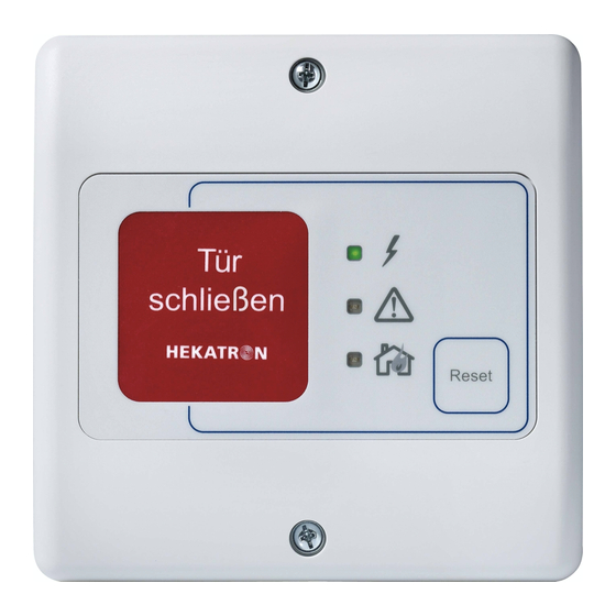
9 Electrical installation 9.7 Signalling of the FSZ Basis The keypad features three LEDs which signal the status of the system. LED green LED orange LED red Fig. 12: FSZ Basis keypad 9.7.1 Flashing sequences The LEDs feature different flashing sequences to indicate the different statuses. - Page 28 Actuation of the external External manual manual release button; release button fault of termination module AM 142 Fault at FSZ Fault at FSZ Basis Replace the device Basis Flashes Fault in smoke System with line surveil- System with line switch stub...
- Page 29 HAT. configuration or check and reconnect the lines. Flashes Excess tempera- Ambient temperature Reduce the ambient ture in FSZ Basis too high temperature Flashes Fault in the Short-circuit of the con- Check and reconnect loop of the...
-
Page 30: Commissioning And Acceptance
10 Commissioning and acceptance 10 Commissioning and acceptance 10.1 Acceptance testing After a hold-open system has been installed ready for operation at the place of use, its proper func- tion and installation according to instructions – including closing range monitoring safety devices, if any are provided –... -
Page 31: Maintenance Instructions
10 Commissioning and acceptance 10.2 Maintenance instructions The applicant for the general building type approval must ensure that written maintenance instructions are included in the delivery of the respective design variant of the hold-open system (according to the devices used). The maintenance instructions must clearly specify the activities to be carried out to ensure that the built-in hold-open system fulfils its tasks even after a long period of use. -
Page 32: Functional Test
10 Commissioning and acceptance 10.5 Functional test The functional test of a hold-open system comprises the following checks: a) Manual release (manual release button or, if allowed, by manually pushing the off button) b) Release of the hold-open system by testing the fire detectors using the test procedures defined by the manufacturer of the fire detectors (e.g. - Page 33 11 Maintenance 11 Maintenance The maintenance of the hold-open system must comprise the elements of a functional test (according DIN 14677 Section 6.1.1) and, additionally, the following elements: a) Check for compliance with the documentation and the building type approval; b) Cleaning of the functionally relevant components of the hold-open system, as far as contamiati- on can lead to impairment;...
- Page 34 12 Annex 12 Annex 12.1 Order data FSZ Basis 31-5400002-01-xx Accessories kit 31-4100010-02-xx Termination module 142 (AM 142) 31-5700002-01-xx Magnet line surveillance QUP 10 31-4100015-01-xx Servicing and maintenance set IW Set RS 7001949 12.2 Drilling template See following page. 12.3...
- Page 35 EN 14637 – DIP 1 ......17 Power supply connection ....13 Product description ......7 Flashing sequences ......27 FSZ Basis ..........7 Recommended line type ..... 13 FSZ Basis – applications ..... 11 Reset button ........7 Functional test ........32...
- Page 40 Hekatron Vertriebs GmbH Brühlmatten 9 D-79295 Sulzburg Techn. Support +49 (0) 7634 500 - 8050 A company of the rs-info@hekatron.de Securitas Group Switzerland www.hekatron.de...
Need help?
Do you have a question about the FSZ Basis and is the answer not in the manual?
Questions and answers