Table of Contents
Advertisement
Quick Links
Instruction manual
Explosion proof
Flow Measurement and control
ATEX
Doc. no.: 9.17.028U Date: 25-06-2020
ATTENTION
Please read this instruction manual carefully before installing and operating the instrument.
Not following the guidelines could result in personal injury and/or damage to the equipment.
Related drawing.
No modifications permitted without
approval of the authorised person.
Advertisement
Table of Contents

Related Manuals for BRONKHORST F-112AX


Summary of Contents for BRONKHORST F-112AX
- Page 1 Instruction manual Explosion proof Flow Measurement and control ATEX Doc. no.: 9.17.028U Date: 25-06-2020 ATTENTION Please read this instruction manual carefully before installing and operating the instrument. Not following the guidelines could result in personal injury and/or damage to the equipment. Related drawing.
- Page 2 BRONKHORST ®...
- Page 3 However, if the product has been returned collect to Bronkhorst High-Tech B.V., these costs are added to the repair invoice. Import and/or export charges, foreign shipping methods/carriers are...
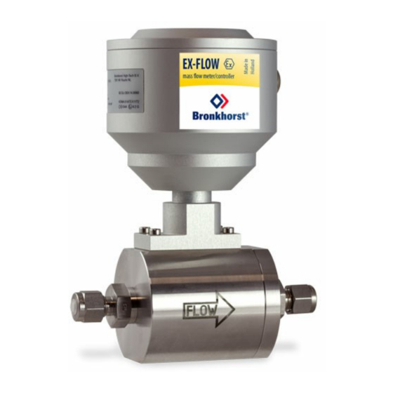
- Page 4 BRONKHORST ® Short-Form Operation Instruction Before installing your Mass Flow Meter/Controller it is important to read the attached label and check: - flow rate - fluid to be metered - up- and downstream pressures - input/output signal Check the red-coloured sticker and make sure the test pressure is in agreement with normal safety factors for your application.
-
Page 5: Table Of Contents
Control system with XC-coil ..................... page 16 Control system with XB-coil ..................... page 16 EMC and cables ........................page 17 4.5.1 Cable gland assembly Bronkhorst flowhead ................. page 17 ® 4.5.2 Cable gland assembly XC / XB coil ..................page 17 Maintenance General ............................ - Page 6 BRONKHORST ® Appendices Enclosures...
-
Page 7: Intrinsic Safe Sensors
The system can be completed with a control valve and flexible readout to measure and control gasflows from 0 5 ml / min − up to 1000 m Model F-112AX 1.2 Bronkhorst ® flowhead The X100 flowhead has the following type of protection:... -
Page 8: Software For Conversion Factor Calculation
BRONKHORST ® 1.3 Software for conversion factor calculation Bronkhorst gathered the physical properties of over 600 fluids in a database called FLUIDAT ® Application software, such as FLUIDAT on the Net (FOTN), enable the user to calculate accurate ... -
Page 9: Ex-Proof Coils
BRONKHORST ® 1.5 Ex-proof Coils 1.5.1 Introduction In our program we know two sorts of coils: (1) Style: XC = II 2 G Ex eb IIC T4 II 2 D Ex tb IIIC T130°C Increased safety coil with LCIE approval. -
Page 10: Style Xb-Coil
BRONKHORST ® 1.5.3 Style XB coil Manufacturer : Parker Lucifer Type : 48.8650 Type of protection : II 1 G Ex ia IIC T6 II 1 D Ex ta IIIC T80°C Certificate no. : LCIE 02 ATEX 6024 X Housing : polyamid with fiberglass housing / IP 66 Max.supply voltage... -
Page 11: Installation
If the instruments have been used with toxic or dangerous fluids the customer should pre-clean the instrument. Important: Clearly note, on top of the package, the customer clearance number of Bronkhorst High-Tech B.V., namely: NL801989978B01 If applicable, otherwise contact your distributor for local arrangements. -
Page 12: Mounting
® 2.4 Mounting The mounting position depends on the type of meter. The preferred position is horizontal and at high pressures (> 10 bar), Bronkhorst strongly advices to mount the instrument in this position. Avoid installation ® in close proximity of mechanic vibration and/or heat sources. -
Page 13: Piping
BRONKHORST ® 2.7 Piping BE SURE THAT PIPING IS ABSOLUTELY CLEAN! DO NOT install small diameter piping on high flowrates, because the inlet jetflow will affect the accuracy. DO NOT mount abrupt angles direct on in- and outlet, especially not on high flow rates. We recommend at least 10 pipe diameters distance between the angle and the instrument. -
Page 14: Supply Pressure
BRONKHORST ® 2.10 Supply pressure Do not apply pressure until electrical connections are made. When applying pressure to the system, take care to avoid pressure shocks in the system and increase pressure gradually, especially on high pressure units incorporating a membrane/piston operated control valve. -
Page 15: Operation
BRONKHORST ® 3 OPERATION 3.1 General The Bronkhorst Mass Flow Meters/Controllers are designed in such a way that they will meet user process ® requirements. 3.2 Power and warm-up Before switching on power check if you have connected all the pins according to the hook-up diagram which belongs to the flow meter/controller. -
Page 16: Cables
® flowhead uses two-wire Lapp Unitronic LiYCY shielded cable. Bronkhorst ® When using a Bronkhorst Readout unit E-7000/E-8000 series and Bronkhorst cables, the maximum cable ® ® length is 400 meter. When using a non Bronkhorst Readout unit and cables, the total system should comply with the Ex ®... -
Page 17: Emc And Cables
Readout units with its intrinsic safe isolating repeaters should be situated outside zone 2. 4.5.1 Cable gland assembly Bronkhorst ® flowhead Do not connect the cable shield to the Bronkhorst ® flowhead. See included hook-up diagram. 4.5.2 Cable gland assembly XC coil For assembling the cable to the coil follow the instructions of the manufacturer of the coil and cable gland. -
Page 18: Maintenance
BRONKHORST ® 5 MAINTENANCE 5.1 General At normal use, no routine maintenance is required to be performed on the meters or controllers. Units may be flushed with clean, dry inert gas. For further information contact supplier or factory. 5.2 Calibration All flow meters are factory calibrated. -
Page 19: Troubleshooting
BRONKHORST ® 6 TROUBLESHOOTING 6.1 General For a correct analysis of the proper operation of a mass flow meter/controller it is recommended to remove the unit from the process line and to check it without applying gas supply pressure. In case the unit is dirty, this can be ascertained immediately by loosening the compression type couplings and, if applicable, the flange on the inlet side. - Page 20 BRONKHORST ® page 20 9.17.028...
- Page 21 BRONKHORST ® APPENDIX 1 Enclosures (if applicable) EC Declaration of Conformity * Calibration certificate(s) Declaration on contamination Dimensional drawings Translation of essential safety instructions (enclosed by order and available on Documentation / software tool CD) EC Type Examination certificate **...
Need help?
Do you have a question about the F-112AX and is the answer not in the manual?
Questions and answers